EP1092969A2 - Verfahren zum Ermitteln der Tumble-Zahl an einem Verbrennungsmotor - Google Patents
Verfahren zum Ermitteln der Tumble-Zahl an einem Verbrennungsmotor Download PDFInfo
- Publication number
- EP1092969A2 EP1092969A2 EP00120191A EP00120191A EP1092969A2 EP 1092969 A2 EP1092969 A2 EP 1092969A2 EP 00120191 A EP00120191 A EP 00120191A EP 00120191 A EP00120191 A EP 00120191A EP 1092969 A2 EP1092969 A2 EP 1092969A2
- Authority
- EP
- European Patent Office
- Prior art keywords
- cylinder
- flow
- tumble
- geometric model
- anemometer
- Prior art date
- Legal status (The legal status is an assumption and is not a legal conclusion. Google has not performed a legal analysis and makes no representation as to the accuracy of the status listed.)
- Withdrawn
Links
- 238000000034 method Methods 0.000 title claims abstract description 19
- 238000002485 combustion reaction Methods 0.000 title claims description 7
- 238000012360 testing method Methods 0.000 abstract description 20
- 238000005094 computer simulation Methods 0.000 abstract 2
- 238000004364 calculation method Methods 0.000 description 18
- 238000005259 measurement Methods 0.000 description 13
- 238000009826 distribution Methods 0.000 description 8
- 238000004088 simulation Methods 0.000 description 6
- 238000005457 optimization Methods 0.000 description 5
- 238000013459 approach Methods 0.000 description 2
- 230000000694 effects Effects 0.000 description 2
- XLYOFNOQVPJJNP-UHFFFAOYSA-N water Substances O XLYOFNOQVPJJNP-UHFFFAOYSA-N 0.000 description 2
- WANLLPADDCXPGO-WMKJBNATSA-N (6r,9s,12s)-3-[(2s)-butan-2-yl]-6-[(4-methoxyphenyl)methyl]-9-[6-(oxiran-2-yl)-6-oxohexyl]-1,4,7,10-tetrazabicyclo[10.4.0]hexadecane-2,5,8,11-tetrone Chemical compound C([C@@H]1C(=O)NC(C(N2CCCC[C@H]2C(=O)N[C@@H](CCCCCC(=O)C2OC2)C(=O)N1)=O)[C@@H](C)CC)C1=CC=C(OC)C=C1 WANLLPADDCXPGO-WMKJBNATSA-N 0.000 description 1
- 230000006978 adaptation Effects 0.000 description 1
- 230000015572 biosynthetic process Effects 0.000 description 1
- 238000007796 conventional method Methods 0.000 description 1
- 238000013461 design Methods 0.000 description 1
- 238000004519 manufacturing process Methods 0.000 description 1
- 238000013178 mathematical model Methods 0.000 description 1
- 239000000203 mixture Substances 0.000 description 1
- 230000002093 peripheral effect Effects 0.000 description 1
- 230000036962 time dependent Effects 0.000 description 1
- 230000007704 transition Effects 0.000 description 1
- 239000013598 vector Substances 0.000 description 1
- 230000000007 visual effect Effects 0.000 description 1
Images



Classifications
-
- G—PHYSICS
- G01—MEASURING; TESTING
- G01M—TESTING STATIC OR DYNAMIC BALANCE OF MACHINES OR STRUCTURES; TESTING OF STRUCTURES OR APPARATUS, NOT OTHERWISE PROVIDED FOR
- G01M15/00—Testing of engines
Definitions
- the present invention relates to a method for determining the tumble number of a Charge mass that flows into a cylinder of an internal combustion engine.
- the tumble number is a parameter of the so-called tumble flow, one Vortex flow that occurs during the suction of the charge mass into a cylinder an internal combustion engine in the cylinder.
- FIG. 1 The three phases of creating a tumble flow depending on valve and Piston stroke are shown in Figure 1.
- the figure shows a cylinder 1 and one of which by an inlet valve 3 offset inlet channel 2 in three phases of the mixture intake stroke.
- phase I with a small stroke of the valve, the inflowing occurs Charge mass largely evenly over the entire valve gap area in the Cylinder 1 a.
- the upper area of the valve gap becomes larger as the valve lift increases the geometric structure of the inlet channel 2 increasingly favored.
- the necessary Flow deflection is lower at the top than in the lower area of the valve gap. Because the Charge mass speed clearly indicates the speed of the piston exceeds, the flow is deflected from the piston crown towards the cylinder head.
- the intensity of this tumble flow can be measured using a so-called tumble test bench be determined.
- FIG. 2 shows the principle of a tumble test stand suitable for this type of measurement.
- the channel flow into a cylinder 1 with a fixed flat-bottomed piston 4 initiated.
- the side wall of the cylinder 1 is in partially omitted from the figure around a rotatably arranged inside the cylinder
- impeller 7, which is part of an anemometer which is the strength of the Tumble flow in the cylinder 1 based on the speed of the impeller 7 around its shaft 8 measures.
- the shaft 8 with a 5 mm diameter extends freely through two (not shown) lateral outlet openings in the wall of the cylinder 1, through the Charge mass can flow out of the cylinder 1 into an outlet chamber.
- outlet chamber is a cylindrical tube section in which the measuring cylinder is coaxially immersed (see also Figure 4b). The The outlet chamber is closed at its upper end and open at the bottom.
- the mass flow, the ambient pressure and the temperature are also tested on the test bench measured in the air.
- the tumble number is determined after the test bench measurements with the following Equations:
- the measurements are determined over the course of the valve stroke.
- the valve stroke (h) is set to 1 mm and a constant pressure difference of 150 mm water column is generated in the cylinder. This creates a constant mass flow in the cylinder and the impeller rotates at a constant angular velocity.
- the measured values are saved and the next valve stroke is set and measured. Measurements are successively made for 1.0 mm ⁇ h ⁇ 10.0 mm. Then measurement data are recorded in the opposite way from 10.0 to 1.0 mm.
- the normalized tumble numbers ( T *) for a typical four-valve inlet duct are shown in FIG. 3. It can be seen that the tumble numbers agree well with low and high valve strokes. With small valve gaps, no tumble flow can be seen.
- the value of the tumble number depends on the geometry of the cylinder head whose valve or valves the charge mass flows in, and it is also affected the shape of the intake ducts through which the charge mass is supplied to the valves becomes.
- Measurements of the tumble number on such a test bench are costly and time-consuming, because for each measurement a completely shaped inlet channel or a machined cylinder head are required. There is one for each optimization step Revision of their shape or even a new production required. Therefore, it is desirable already through a pre-optimized channel respectively Cylinder geometry available before the first measurements are carried out on the test bench in order to reduce the number of optimization steps required.
- the conventional approach to determining the tumble number is therefore the measurement on the known test bench using a physical model.
- the object of the invention is to provide a method for determining the tumble number which at least a pre-optimization of the with little time and cost Flow conditions of the charge mass allowed on an internal combustion engine.
- Geometric model is generated that has at least the dimensions of the cylinder describes the dimensions of at least the moving parts of the anemometer neglected and in the case of the geometric model a flow differential equation system is solved and the tumble number based on the obtained Velocity values of the flow in that partial volume of the cylinder are determined is in which the moving parts of the commonly used anemometer would move.
- Such an approximation is expedient since it takes up the computational effort for the solution of the system of differential equations is considerably simplified, and because it can be assumed that these moving parts are only negligible Will have a braking effect on the flow in the cylinder.
- the shape of the anemometer can be completely neglected in the geometric model to keep the computing effort low and the computing times short.
- a better approximation of the actual flow conditions is given at Fixed shaft anemometer achieved in that the dimensions of the shaft of be described in the geometric model.
- an intake port extending from the cylinder through a Inlet valve is discontinued, part of the geometric model.
- the tumble number advantageously a mean value on an axis of rotation of the Anemometer-related angular velocity of the flow over that Partial volume are formed in which the moving parts of the anemometer move.
- the moving parts of the anemometer can in particular consist of a circular disk exist that defines a spherical partial volume. Their diameter can be in be substantially equal to the inside diameter of the cylinder.
- FIG. 4A shows a first, simple geometric model of a cylinder 1 Internal combustion engine with an associated intake port 2.
- the cylinder and the Inlet channels have a plane of symmetry perpendicular to the x-axis of the figure. For one numerical simulation of the flow ratio in them is therefore sufficient, in each case half to consider. Accordingly, the cylinder 1 and the Flow channel 2 is shown half in the figure, the part omitted in the model is in the figure indicated by dashed outline.
- the inlet duct 2 bifurcates in each of the two before reaching cylinder 1 forked pieces, a valve is arranged, the guide tube 9 shown in the figure is. Charge mass entering cylinder 1 through the valve leaves the cylinder via an outlet opening, which in the simple model shown here by a Pipe socket 10 is approximated.
- This simple geometric model only contains Information about the shape of the cylinder and the inlet channel, but not about the the test bench in which they are installed.
- FIG. 4B corresponds in its inlet duct 2 and in the head of cylinder 1 the model from Figure 4A and must therefore in this area will not be described again.
- the lower part of the cylinder 1 dips into one cylindrical outlet chamber 11 of the test bench, and with this by two circular cutouts 12 connected in its side wall, which are dashed in the figure are shown. Through these cutouts 12 extends one (in the figure of For the sake of clarity, not shown) round wave, in two opposite Recesses 13 of the outlet chamber 11 is mounted.
- This wave corresponds to the wave of the anemometer commonly used on a tumble test bench, the geometric model representing the figure.
- the shaft turns at the Flow measurements, but their shape is unchangeable. That is why it is used in geometric model approximated as unmoving.
- the impeller, which in practice the shaft is not part of the geometric model.
- Geometric models of the type shown in FIGS. 4A and 4B can be used, for example, with With the help of a standard CAD program.
- the flow distribution in the models is calculated using a finite volume calculation program carried out.
- This program solves three-dimensionally the continuity equation for compressible or incompressible media Navier-Stokes equation and the energy transport equation.
- Ability in particular for time-dependent calculation is important, and that shown in Figure 3 To be able to reproduce hysteresis behavior in a model.
- the turbulence model is the standard k- ⁇ model known from Launder, BE and Spalding, DB, Mathematical Models of Turbulence, Academic Press, New York 1972. It is based on isotropic turbulence at high Reynolds numbers.
- the equations are implicitly solved by iterative or Predictor-Corrector "methods.
- An orthogonally structured Cartesian calculation grid is used in which wall cell volume and surface adaptation is carried out.
- the calculation grids are generated automatically with a grid generator. Areas with local grid refinement are used to improve the resolution of the flow areas on the wall and in areas where there are high velocity gradients, such as in the valve gap, and the usual logarithmic approach (wall law) is used to determine the flow boundary layer on the wall.
- Figures 5A and 5B each show side views of the calculation grids for the two Models from Figure 4A or 4B with a valve stroke of 10 mm.
- the calculation grid is finer than in Starting area of the inlet channel 2 or in the lower area of the cylinder 1.
- the area around the head 3a of the valve 3, in the area 51, is the calculation grid refined again.
- the calculation grid is in the range of Cylinder 1 and the inlet duct 2 are distributed similarly finely as in the model of FIG. 5A.
- the grille is essential rougher.
- the tumble test bench uses a constant pressure drop of 150 mm water column, to move the cargo mass. You could use this for the calculations Pressure drop as flow boundary conditions directly on the inlet and outlet surfaces of the model. For the test bench mentioned above, this is not practical, because the pressure on the test bench is measured directly in the cylinder on the wall. Alternatively were therefore the measured mass flows on the tumble test bench at the different valve stroke positions used as a boundary condition for the calculation. It calculation grids with valve strokes of 6, 8 and 10 mm for both model variants simulated. Since the inlet channel and the tumble test bench are mirror symmetrical, only half the calculation grid is used for the simulations. This will the calculation times halved again.
- the simplified models were on a Single processor calculator and the detailed model was compiled using a 4-processor workstation calculated in parallel.
- This calculation provides the distribution of the flow velocity of the charge mass within the model under consideration.
- tangential velocity c T and axial velocity c A in the cylinder are required, as stated at the beginning.
- the axial speed can be obtained by integrating the axial components of the speed distribution over a cross section of the cylinder.
- the angular velocity of the flow with respect to the shaft axis is integrated over the partial volume of the cylinder by moving the impeller, and an average of this angular velocity is obtained by dividing by the volume. This mean is equated with the angular velocity of the impeller.
- the tumble number can now be calculated using the formulas (1) and (3) listed at the beginning.
- the figures 6A, 6B show a section in the yz plane of FIG 4A and 4B parallel plane with a stroke of the valve of 10 mm, viewed from the side for both model variants.
- the flows in intake port 2, in the valve gap and in the cylinder 1 look very similar.
- a large swirl 61 is closed in the lower valve gap area recognize that meets the valve gap.
- the main flow is in the upper valve gap 62, as is to be expected according to that in FIG. 1 with reference to FIG described phases. If you look at the flow in the cylinder, you will notice one very good tumble flow from with the center of the vortex in the same place in both Model variants.
- the vortex center is 4 mm to the left of the cylinder center and 6 mm above the axis of the side exit.
- the shaft 8 of the impeller is in the detailed Recognize model of Figure 6B.
- the flow in the outer outlet chamber 11 of the detailed model has a small amount compared to the flow velocity in the cylinder.
- the inlet duct geometry is identical for both models.
- the velocity of the main flow is analyzed with high local resolution.
- figure 7 shows the profile of the speed amount on the line VII-VII of the figures 6A, 6B, the 8 mm above the nip plane (bottom of the cylinder head) and in the same longitudinal section plane as in Figure 6A, 6B.
- the simplified model has one maximum amount of 51.5 m / s, the detailed model has a slightly smaller value 49.7 m / s.
- the simplified model has the higher maximum speed amount, but it also drops faster than that of the detailed model. You can see that the flow of the detailed model fills the valve gap better and not as steep in flows into the cylinder, as is shown in the simplified model. Since the current in the Valve gap is not identical, it is expected that the cylinder flow will not will be identical.
- FIG. 9 shows the W component of the Flow velocity (in the axial z-direction) on a line through the center of the Cylinder in the middle plane of the exit. This line is shown in FIGS. 8A and 8B Designated IX-IX. It can be seen that the speed of the detailed model almost over the entire cylinder radius has a higher value than that of the simplified one Model.
- the maximum W speeds are 48.3 and -49.4 m / s for that simplified model as well as 52.6 and -53.1 m / s for the detailed model. This results a greatest difference in the maximum W speeds between the two Model variants of 8%.
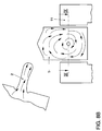
- Figures 10A, 10B show the velocity vectors in a plane through the center of the cylinder.
- the flow due to the outlet geometry assumed as the pipe socket 10, can only flow out perpendicular to the outlet axis in a rotating movement (initiated by the tumble flow).
- the detailed model (FIG. 10B) has a much more complicated flow with vortices above the shaft and behind the cutout due to the shaft 8, the cutout 12 in the cylinder wall and the air duct in the outlet chamber 11.
- a main flow in the outer area can be seen under the shaft with a 45 degree inclination.
- Table 1 shows the calculated and measured normalized tumble numbers.
- the simplified model results in tumble numbers that are approximately 11% below the measured tumble numbers. This means that due to its assumed outflow geometry, the simplified model delivers an approximately constant relative deviation for large valve strokes. With a valve stroke of 6 mm, there is an approx. 40% deviation compared to the measured tumble number.
- FIG. 11 shows a graphic representation of the Comparison of the calculated and measured tumble numbers.
Landscapes
- Physics & Mathematics (AREA)
- General Physics & Mathematics (AREA)
- Testing Of Engines (AREA)
- Combustion Methods Of Internal-Combustion Engines (AREA)
Abstract
Description

In Tabelle 1 sind die berechneten und gemessenen normierten Tumble-Zahlen gegenübergestellt. Bei 10 und 8 mm Ventilhub ergibt das vereinfachte Modell Tumble-Zahlen, die ungefähr 11 % unter den gemessenen Tumble-Zahlen liegen. Das heißt, dass durch seine angenommene Ausström-Geometrie das vereinfachte Modell bei großen Ventilhüben eine etwa konstante relative Abweichung liefert. Bei einem Ventilhub von 6 mm treten ca. 40% Abweichung gegenüber der gemessenen Tumble-Zahl auf.


Claims (7)
- Verfahren zum Ermitteln der Tumble-Zahl einer Ladungsmasse, die in einen Zylinder (1) eines Verbrennungsmotors einströmt, dadurch gekennzeichnet, daß in einem Computer ein geometrisches Modell erzeugt wird, das wenigstens die Abmessungen des Zylinders (1) beschreibt, die Abmessungen zumindest der beweglichen Teile (7) eines üblicherweise verwendeten Anemometers aber vernachlässigt, daß für das geometrische Modell ein Strömungs-Differentialgleichungssystem gelöst wird, und daß die Tumble-Zahl anhand der erhaltenen Geschwindigkeitswerte der Strömung in demjenigen Teilvolumen des Zylinders (1) bestimmt wird, in dem sich die beweglichen Teile (7) des üblicherweise verwendeten Anemometers bewegen würden.
- Verfahren nach Anspruch 1, dadurch gekennzeichnet, daß das geometrische Modell die Abmessungen der bei dem üblicherweise verwendeten Anemometer angeordneten ortsfeste Welle (8) beschreibt.
- Verfahren nach Anspruch 1, dadurch gekennzeichnet, daß das geometrische Modell das üblicherweise verwendete Anemometer vollständig vernachlässigt.
- Verfahren nach einem der vorhergehenden Ansprüche, dadurch gekennzeichnet, daß das geometrische Modell ferner die Gestalt eines Einlaßkanals (2) beschreibt, der vom Zylinder durch ein Einlaßventil (3) abgesetzt ist.
- Verfahren nach einem der vorhergehenden Ansprüche, dadurch gekennzeichnet, daß das geometrische Modell Austrittsöffnungen, aus denen die Ladungsmasse aus dem Zylinder (1) ausströmt, als Rohrabschnitte (10) approximiert.
- Verfahren nach einem der Ansprüche 1 bis 4, dadurch gekennzeichnet, daß das geometrische Modell ferner die Gestalt eines Auslaßbereichs (11) beschreibt, in den die Ladungsmasse aus dem Zylinder (1) ausströmt.
- Verfahren nach einem der vorhergehenden Ansprüche, dadurch gekennzeichnet, daß für die Bestimmung der Tumble-Zahl ein Mittelwert der auf eine Drehachse des üblicherweise verwendeten Anemometers bezogenen Winkelgeschwindigkeit der Strömung über das Teilvolumen gebildet wird.
Applications Claiming Priority (2)
| Application Number | Priority Date | Filing Date | Title |
|---|---|---|---|
| DE1999149876 DE19949876A1 (de) | 1999-10-15 | 1999-10-15 | Verfahren zum Ermitteln der Tumble-Zahl an einem Verbrennungsmotor |
| DE19949876 | 1999-10-15 |
Publications (2)
| Publication Number | Publication Date |
|---|---|
| EP1092969A2 true EP1092969A2 (de) | 2001-04-18 |
| EP1092969A3 EP1092969A3 (de) | 2003-04-16 |
Family
ID=7925844
Family Applications (1)
| Application Number | Title | Priority Date | Filing Date |
|---|---|---|---|
| EP00120191A Withdrawn EP1092969A3 (de) | 1999-10-15 | 2000-09-22 | Verfahren zum Ermitteln der Tumble-Zahl an einem Verbrennungsmotor |
Country Status (2)
| Country | Link |
|---|---|
| EP (1) | EP1092969A3 (de) |
| DE (1) | DE19949876A1 (de) |
Cited By (2)
| Publication number | Priority date | Publication date | Assignee | Title |
|---|---|---|---|---|
| WO2014079059A1 (zh) * | 2012-11-26 | 2014-05-30 | Lu Ming | 测量发动机滚流进气系统的性能的稳流试验台 |
| CN113405803A (zh) * | 2021-08-19 | 2021-09-17 | 潍柴动力股份有限公司 | 一种滚流测试工装与一种滚流测试设备 |
Families Citing this family (1)
| Publication number | Priority date | Publication date | Assignee | Title |
|---|---|---|---|---|
| DE102006051568A1 (de) * | 2006-11-02 | 2008-05-08 | Fev Motorentechnik Gmbh | Optimierung einer Zylinderinnenströmung |
Citations (2)
| Publication number | Priority date | Publication date | Assignee | Title |
|---|---|---|---|---|
| US5072613A (en) * | 1989-12-14 | 1991-12-17 | Chrysler Corporation | Method for evaluation of fluid flow within a simulated combustion chamber |
| DE4133277A1 (de) * | 1991-10-08 | 1993-04-15 | Fev Motorentech Gmbh & Co Kg | Einrichtung zur untersuchung der stroemungsbewegung in zylindrischen bauteilen |
Family Cites Families (7)
| Publication number | Priority date | Publication date | Assignee | Title |
|---|---|---|---|---|
| DE2613275C2 (de) * | 1976-03-27 | 1985-01-31 | Götz Dipl.-Ing. 7106 Neuenstadt Tippelmann | Drall-Meßeinrichtung |
| US5487365A (en) * | 1991-02-21 | 1996-01-30 | Yamaha Hatsudoki Kabushiki Kaisha | Induction system for engine |
| DE4437947C2 (de) * | 1994-10-24 | 1998-03-19 | Daimler Benz Ag | Verfahren zur Regelung der Zuführung von wenigstens einem Zusatzfluidstrom in einen Ansaugtrakt einer Brennkraftmaschine und Vorrichtung zur Durchführung des Verfahrens |
| DE19619782C2 (de) * | 1995-05-15 | 1999-05-27 | Mitsubishi Motors Corp | Einlaßsystem für eine Verbrennungskraftmaschine |
| DE19535486C1 (de) * | 1995-09-23 | 1996-12-05 | Bayerische Motoren Werke Ag | Drall-Meßverfahren für einen simulierten Verbrennungsraum eines Kolbenmotors und Vorrichtung zur Durchführung eines Drall-Meßverfahrens |
| DE19752118C1 (de) * | 1997-11-25 | 1999-03-18 | Bayerische Motoren Werke Ag | Verfahren zur Überprüfung der Wirkung von Drallkanälen bei mehrzylindrigen Brennkraftmaschinen, insbesondere bei Direkteinspritzmotoren |
| DE19827463A1 (de) * | 1998-06-19 | 1999-12-23 | Fev Motorentech Gmbh | Direkteinspritzender Dieselmotor mit tumblegestütztem Brennverfahren |
-
1999
- 1999-10-15 DE DE1999149876 patent/DE19949876A1/de not_active Withdrawn
-
2000
- 2000-09-22 EP EP00120191A patent/EP1092969A3/de not_active Withdrawn
Patent Citations (2)
| Publication number | Priority date | Publication date | Assignee | Title |
|---|---|---|---|---|
| US5072613A (en) * | 1989-12-14 | 1991-12-17 | Chrysler Corporation | Method for evaluation of fluid flow within a simulated combustion chamber |
| DE4133277A1 (de) * | 1991-10-08 | 1993-04-15 | Fev Motorentech Gmbh & Co Kg | Einrichtung zur untersuchung der stroemungsbewegung in zylindrischen bauteilen |
Non-Patent Citations (2)
| Title |
|---|
| ENDRES H. ET AL.: "Verbrauchs- und Emissionsminderung bei Mehrventil-Ottomotoren durch Anwendung von Drall und Tumble", 3E AACHENER KOLLOUIUM FAHRZEUG- UND MOTORENTECHNIK, 1991, XP002997867 |
| NAJIPOOR-SCHUETTE: "Three-dimantional computation and experimental flow investigation of intake port/cylinder configuration for S.I. engines", DISSERTATION, 1993, pages 1 - 143 +COVER, CONTENT, XP002997866 |
Cited By (3)
| Publication number | Priority date | Publication date | Assignee | Title |
|---|---|---|---|---|
| WO2014079059A1 (zh) * | 2012-11-26 | 2014-05-30 | Lu Ming | 测量发动机滚流进气系统的性能的稳流试验台 |
| CN113405803A (zh) * | 2021-08-19 | 2021-09-17 | 潍柴动力股份有限公司 | 一种滚流测试工装与一种滚流测试设备 |
| CN113405803B (zh) * | 2021-08-19 | 2021-12-17 | 潍柴动力股份有限公司 | 一种滚流测试工装与一种滚流测试设备 |
Also Published As
| Publication number | Publication date |
|---|---|
| DE19949876A1 (de) | 2001-04-19 |
| EP1092969A3 (de) | 2003-04-16 |
Similar Documents
| Publication | Publication Date | Title |
|---|---|---|
| DE102019102835B4 (de) | Steuervorrichtung eines Verbrennungsmotors | |
| AT518850B1 (de) | Verfahren zur simulationsbasierten Analyse eines Kraftfahrzeugs | |
| DE102007021592B4 (de) | Verfahren für die erstellung eines maschinenkennfelds und -modells während eines entwicklungsprozesses einer brennkraftmaschine | |
| DE112019000020B4 (de) | Maschinenlernsystem | |
| DE4139359A1 (de) | Windkanal mit freistrahlmessstrecke zur simulation von windrichtungsschwankungen | |
| DE112010003671T5 (de) | Wirbelgenerator für erweiterte Strömungsbereiche und schnellere Antwort | |
| DE102021116546A1 (de) | Verfahren zum entwerfen und herstellen eines hydraulikventilblocks basierend auf selektivem laserschmelzen | |
| DE102024103246A1 (de) | Optimierungsverfahren und -vorrichtung für die Kammertrennwandstruktur einer vertikal geschlitzten Fischtreppe | |
| WO2014015974A2 (de) | Verbesserte versuchsdurchführung | |
| DE102006016311B4 (de) | Verfahren und Vorrichtung zum Erhalten einer verbesserten Genauigkeit und eines verbesserten Bereichs für Luftdatenparameter, die von unabhängigen Messungen voneinander abhängiger Drücke abgeleitet werden | |
| DE69936066T2 (de) | Kohlenwasserstoffspeicher-prüfung | |
| DE102005014871A1 (de) | Laufschaufelformkonstruktionsprogramm und Verfahren | |
| EP2088486B1 (de) | Verfahren zur Vermessung eines nichtlinearen dynamischen realen Systems mittels Versuchsplanung | |
| EP0611955A2 (de) | Einrichtung zur Untersuchung der Strömungsbewegung in zylindrischen Bauteilen | |
| DE19949876A1 (de) | Verfahren zum Ermitteln der Tumble-Zahl an einem Verbrennungsmotor | |
| DE2613275A1 (de) | Vorrichtung zur untersuchung und abstimmung der drallstroemung in verbrennungsraeumen | |
| Shaw et al. | Study of dimple effect on aerodynamic drag characteristics of a car | |
| DE102008036042A1 (de) | Pulserzeugungseinheit und Prüfstand damit | |
| DE102020103264A1 (de) | Automatisierte Quellidentifizierung aus Mikrofonarraydaten | |
| DE102015118941B4 (de) | Probabilistisches Verfolgungsverfahren für Partikel in einem Fluid | |
| DE102015102891A1 (de) | Höhensimulationsmessstand für einen Verbrennungsmotor sowie Verfahren zum Betreiben eines Höhensimulationsmessstandes für einen Verbrennungsmotor | |
| DE202023101859U1 (de) | Ein System zur Untersuchung der Leistung einer zweiblättrigen zweistufigen Savonius-ähnlichen hydrokinetischen Turbine bei niedrigen Strömungsgeschwindigkeitsbedingungen | |
| DE102015101228A1 (de) | Verfahren und Anordnung zur Modellierung einer aerodynamisch wirksamen Außenkontur eines Bauteilmodells in einem Windkanal | |
| DE102016203840A1 (de) | Windkanalanordnung und Verfahren zur Bestimmung aerokustischer Eigenschaften | |
| DE102009059931A1 (de) | Ermitteln und Parametrieren von Polynom-Modellen für Verbrennungsmotoren |
Legal Events
| Date | Code | Title | Description |
|---|---|---|---|
| PUAI | Public reference made under article 153(3) epc to a published international application that has entered the european phase |
Free format text: ORIGINAL CODE: 0009012 |
|
| AK | Designated contracting states |
Kind code of ref document: A2 Designated state(s): AT BE CH CY DE DK ES FI FR GB GR IE IT LI LU MC NL PT SE |
|
| AX | Request for extension of the european patent |
Free format text: AL;LT;LV;MK;RO;SI |
|
| PUAL | Search report despatched |
Free format text: ORIGINAL CODE: 0009013 |
|
| AK | Designated contracting states |
Designated state(s): AT BE CH CY DE DK ES FI FR GB GR IE IT LI LU MC NL PT SE |
|
| AX | Request for extension of the european patent |
Extension state: AL LT LV MK RO SI |
|
| 17P | Request for examination filed |
Effective date: 20031016 |
|
| AKX | Designation fees paid |
Designated state(s): AT BE CH CY DE DK ES FI FR GB GR IE IT LI LU MC NL PT SE |
|
| TPAC | Observations filed by third parties |
Free format text: ORIGINAL CODE: EPIDOSNTIPA |
|
| 17Q | First examination report despatched |
Effective date: 20061027 |
|
| STAA | Information on the status of an ep patent application or granted ep patent |
Free format text: STATUS: THE APPLICATION IS DEEMED TO BE WITHDRAWN |
|
| 18D | Application deemed to be withdrawn |
Effective date: 20091006 |