EP1092666A2 - Winding unit for automatic winder - Google Patents
Winding unit for automatic winder Download PDFInfo
- Publication number
- EP1092666A2 EP1092666A2 EP00122016A EP00122016A EP1092666A2 EP 1092666 A2 EP1092666 A2 EP 1092666A2 EP 00122016 A EP00122016 A EP 00122016A EP 00122016 A EP00122016 A EP 00122016A EP 1092666 A2 EP1092666 A2 EP 1092666A2
- Authority
- EP
- European Patent Office
- Prior art keywords
- winding unit
- main body
- support main
- unit constituting
- unit support
- Prior art date
- Legal status (The legal status is an assumption and is not a legal conclusion. Google has not performed a legal analysis and makes no representation as to the accuracy of the status listed.)
- Granted
Links
Images






Classifications
-
- B—PERFORMING OPERATIONS; TRANSPORTING
- B65—CONVEYING; PACKING; STORING; HANDLING THIN OR FILAMENTARY MATERIAL
- B65H—HANDLING THIN OR FILAMENTARY MATERIAL, e.g. SHEETS, WEBS, CABLES
- B65H54/00—Winding, coiling, or depositing filamentary material
- B65H54/70—Other constructional features of yarn-winding machines
-
- B—PERFORMING OPERATIONS; TRANSPORTING
- B65—CONVEYING; PACKING; STORING; HANDLING THIN OR FILAMENTARY MATERIAL
- B65H—HANDLING THIN OR FILAMENTARY MATERIAL, e.g. SHEETS, WEBS, CABLES
- B65H2601/00—Problem to be solved or advantage achieved
- B65H2601/30—Facilitating or easing
- B65H2601/32—Facilitating or easing entities relating to handling machine
- B65H2601/321—Access
-
- B—PERFORMING OPERATIONS; TRANSPORTING
- B65—CONVEYING; PACKING; STORING; HANDLING THIN OR FILAMENTARY MATERIAL
- B65H—HANDLING THIN OR FILAMENTARY MATERIAL, e.g. SHEETS, WEBS, CABLES
- B65H2701/00—Handled material; Storage means
- B65H2701/30—Handled filamentary material
- B65H2701/31—Textiles threads or artificial strands of filaments
Definitions
- the present invention relates to improvements for enabling easy attachment and removal of winding unit constituting devices such as a yarn tension adjusting device and a yarn joining device which constitute a winding unit for an automatic winder.
- a conventional automatic winder is constructed by mounting a plurality of winding units on a base.
- the winding unit comprises a vertically extending winding unit support main body having a plurality of winding unit constituting devices each attached thereto and including a yarn tension adjusting device and a yarn joining device.
- the winding unit for the automatic winder is assembled by sequentially attaching a plurality of members together, for example, attaching a first member to the winding unit support main body, attaching a second member to the first member, and attaching a third member to the second member, and by providing wiring or piping at an appropriate time.
- the winding unit constituting device has a movable member such as an oscillating member
- power can be transmitted to the movable member by connecting, at an appropriate time during assembly, a driven node to a driving node of a transmission mechanism provided in the winding unit support main body, using, for example, an intermediate node therebetween.
- the entire winding unit for the automatic winder is assembled while sequentially attaching together the plurality of members constituting each winding unit constituting device and providing the wiring or piping at an appropriate time to assemble the winding unit constituting device. Accordingly, the winding unit has the following problems:
- Means employed by the present invention to enable a winding unit for an automatic winder to be easily assembled and inspected for maintenance, the winding unit comprising a winding unit constituting device requiring wiring, piping, or the like that uses connectors, and to enable the winding unit constituting device to be easily assembled is a winding unit for an automatic winder comprising winding unit constituting devices attached to a winding unit support main body, wherein the winding unit support main body comprises one of matching junction sections of a connector disposed at a predetermined position thereof, the winding unit constituting devices each comprise a plurality of constituent members assembled together and including an attachment member removably attached to the winding unit support main body as well as the other junction section of the connector disposed at a predetermined position thereof, the constituent members and the other junction section being integrated together, and when the attachment member of the winding unit constituting device is attached to or removed from the winding unit support main body, the junction sections of the connector are joined together or mutually separated, respectively.
- the above winding unit constituting devices are
- the assembled winding unit constituting device can be handled as an integral unit, and when the winding unit constituting device is attached to or removed from the winding unit support main body, the junction sections of the connector are joined together or mutually separated. Consequently, the winding unit for the automatic winder can be easily assembled and inspected for maintenance. Additionally, the winding unit constituting device can be assembled beforehand independently of the assembly of the entire winding unit for the automatic winder, thereby enabling the winding unit constituting device to be easily assembled.
- Means employed by the present invention to enable a winding unit for an automatic winder to be easily assembled and inspected for maintenance, the winding unit comprising a winding unit constituting device requiring power transmission, and to enable the winding unit constituting device to be easily assembled is a winding unit for an automatic winder comprising winding unit constituting devices attached to a winding unit support main body, wherein the winding unit support main body comprises either a driving or a driven node of a transmission mechanism disposed at a predetermined position thereof, the winding unit constituting devices each comprise a plurality of constituent members assembled together and including an attachment nether removably attached to the winding unit support main body as well as the other node of the transmission mechanism disposed at a predetermined position thereof, the constituent members and the other node being integrated together, and when the attachment member of the winding unit constituting device is attached to or removed from the winding unit support main body, the nodes of the transmission mechanism are connected together or mutually separated, respectively.
- the above winding unit constituting devices are provided
- the assembled winding unit constituting device can be handled as an integral unit, and when the winding unit constituting device is attached to or removed from the winding unit support main body, the nodes of the transmission mechanism are connected together or mutually separated. Consequently, the winding unit for the automatic winder can be easily assembled and inspected for maintenance. Additionally, the winding unit constituting device can be assembled beforehand independently of the assembly of the entire winding unit for the automatic winder, thereby enabling the winding unit constituting device to be easily assembled.
- Means employed by the present invention to enable a winding unit for an automatic winder to be easily assembled and inspected for maintenance, the winding unit comprising a winding unit constituting device requiring power transmission as well as wiring, piping, or the like that uses connectors, and to enable the winding unit constituting device to be easily assembled is a winding unit for an automatic winder comprising winding unit constituting devices attached to a winding unit support main body, wherein the winding unit support main body comprises one of matching junction sections of a connector disposed at a predetermined position thereof and either a driving or a driven node of a transmission mechanism disposed at a predetermined position thereof, the winding unit constituting devices each comprise a plurality of constituent member assembled together and including an attachment member removably attached to the winding unit support main body as well as the other junction section of the connector disposed at a predetermined position thereof and the other node of the transmission mechanism disposed at a predetermined position thereof, the constituent members and the other node being integrated together, and when the attachment member of the
- the assembled winding unit constituting device including the other junction section of the connector and the other node of the transmission mechanism, can be handled as an integral unit, and when the winding unit constituting device is attached to or removed from the winding unit support main body, the junction sections of the connector are joined together or mutually separated and the nodes of the transmission mechanism are connected together or mutually separated. Consequently, the winding unit for the automatic winder can be easily assembled and inspected for maintenance. Additionally, the winding unit constituting device can be assembled beforehand independently of the assembly of the entire winding unit for the automatic winder, thereby enabling the winding unit constituting device to be easily assembled.
- Means employed by the present invention to enable a winding unit for an automatic winder to be easily assembled and inspected for maintenance the winding unit comprising a winding unit constituting device requiring wiring, piping, or the like that uses connectors, is a winding unit for an automatic winder, wherein that two of the connectors are disposed each for pneumatic piping and for electric wiring, and when the winding unit constituting device is moved in one direction to attach or remove the winding unit support main body to or from the attachment member, the junction sections of the connector are joined together or mutually separated, respectively.
- the connectors are joined together or mutually separated, thereby enabling the entire winding unit for the automatic winder to be easily assembled and inspected for maintenance.
- the winding unit constituting device is formed into a cassette, so that assembly, inspection, and maintenance operations are advantageously easy and specifications for the automatic winder can advantageously be easily changed.
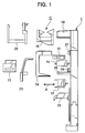
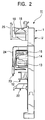
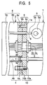
- a winding unit for an automatic winder according to the present invention will be described below based on an embodiment of the present invention shown in Figures 1 to 15.
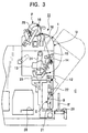
- the automatic winder is constructed by mounting a plurality of winding units 11 on a base as shown in Figure 3.
- the winding unit 11 for the automatic winder according to this embodiment comprises a vertically extending winding unit support main body 1 and one or more winding unit constituting devices 2 attached to the winding unit support main body 1. Principal improvements of this winding unit are listed below.
- the connector 3 is for electric wiring and has the one junction section 3a disposed at a predetermined position of an attachment section 1a comprising a side plate of the winding unit support main body 1, and the other junction 3b disposed at a predetermined position of an attachment member 6a of the winding unit constituting device 2.
- the junction section 3a is either female or male (in the drawings, female), while the junction section 3b is correspondingly either male or female.
- the junction sections 3a, 3b of the connector 3 joint wires such as power wires and/or signal wires together to supply power or communicate signals between the winding unit support main body 1 and the winding unit constituting device 2.
- the connector 4 is for piping for compressed or sucked air and has the one junction section 4a disposed at a predetermined position of the attachment section 1a of the winding unit support main body 1, and the other junction 4b disposed at a predetermined position of the attachment member 6a of the winding unit constituting device 2.
- the junction section 4a is either female or male (in the drawings, male), while the junction section 4b is correspondingly either male or female.
- a seal ring 7 is externally fitted around the male junction section 4a of the connector 4, composed of a pipe, or is internally fitted into the female junction section 4b of the connector 4, composed of a pipe, a gap between the junction sections 4a, 4b is sealed.
- the transmission mechanism 5 has either the driving or driven node 5a (in the drawings, the driving node) disposed at a predetermined position of the winding unit support main body 1, and the other node 5b (in the drawings, the driven node) disposed at a predetermined position of the winding unit constituting device 2.
- the attachment member 6a of the winding unit constituting device 2 is attached to or removed from the winding unit support main body 1, the nodes 5a, 5b of the disposed transmission mechanism 5 are connected together or mutually separated.
- the nodes may be points as shown in the drawings, a combination of a plate cam and a rod which contact mutually on a pair of lines or planes, a combination of a spline shaft and a bearing which mesh mutually (not shown in the drawings), or a combination of two meshing gears, as appropriate.
- One of the nodes 5a, 5b is preferably configured to reciprocate linearly in a direction in which the winding unit constituting device 2 is attached or removed.
- the attachment section 1a of the winding unit support main body 1 and/or the attachment member 6a of the winding unit constituting device 2 has an opening 8 such that one of the nodes can enter the winding unit constituting device 2 or the winding unit support main body 1.
- the attachment section 1a of the winding unit support main body 1 and the attachment member 6a of the winding unit constituting device 2 have one or more sets of positioning means 9 provided at appropriate locations and comprising a pin 9a in the attachment section 1 and a hole 9b in the attachment member 6a.
- the positioning means 9 enables accurate positioning when the attachment section 1a and the attachment member 6a are joined together.
- the attachment section 1a of the winding unit support main body 1 and the attachment member 6a of the winding unit constituting device 2 have one or more sets of connection means 10 provided at appropriate locations and comprising a threaded hole 10a in the attachment section 1a and a bolt 10b in the attachment member 6a.
- the connection means 10 enables firm connection when the attachment section 1a and the attachment member 6a are attached together.
- the connection means 10 places the bolt 10b in the attachment section 6a of the winding unit constituting device 2 so that the bolt 10b will not slip out, and enables the bolt 10b to be easily tightened from the winding unit constituting device 2 if the threaded hole 10a is formed in the attachment section 1a of the winding unit support main body 1.
- a through hole for the bolt 10b in the attachment section 6a may be formed into a threaded hole such as that in the attachment section 1a.
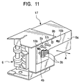
- the winding unit constituting device 2 includes a yarn tension adjusting device 12, a yarn joining device 13, a wax applying device 14, a yarn defect detecting device 15, a drum cover device 16, and a fluff suppressing device 17, which is shown in Figure 11.
- the fluff suppressing device 17 is replaced with the yarn tension adjusting device 12 as required.
- the winding unit support main body 1 extends vertically so as to be inclined toward a front portion C (see Figure 3) corresponding to an operation passage side, and has a drive drum 18 supported thereon in a cantilever manner.
- the yarn tension adjusting device 12 one type of the winding unit constituting device 2, integrally comprises a yarn tension adjusting device main body 6 composed of a plurality of constituent members (an opener, a cutter, and the like) assembled together and including the attachment member 6a removably attached to the winding unit support main body 1, the other junction section 3b of the wiring connector 3, the other junction section 4b of the connector 4 for piping for receiving cleaning compressed air, the driven node 5b, that is, the other node of the transmission mechanism 5 for driving the opener or the like, and a driven node 5'b, that is, the other node of the transmission mechanism 5 for driving the cutter or the like, the hole 9b of the positioning means 9, and the bolt 10b of the connection means 10, which are all arranged at predetermined positions of the yarn tension adjusting means 12.
- a yarn tension adjusting device main body 6 composed of a plurality of constituent members (an opener, a cutter, and the like) assembled together and including the attachment member 6a removably attached to the winding unit support main body 1,
- the winding unit support main body 1 has the one junction section 3a of the wiring connector 3, the one junction section 4a of the piping connector 4, the driving node 5a, that is, the one node of the transmission mechanism 5 for driving the opener or the like, and a driving node (not shown in the drawings), that is, the one node of the transmission mechanism 5 for driving the cutter or the like, the pin 9a of the positioning means 9, and the threaded hole 10a of the connection means 10, which are all arranged at predetermined positions in an area in which the yarn tension adjusting means 12 is mounted.
- connection means 10 When the yarn tension adjusting device 12 is moved in the arrow A direction relative to the attachment section 1a of the winding unit support main body 1 in order to assemble the winding unit 11 for the automatic winder or to inspect it for maintenance, the junction or separation of the connectors 3, 4, the connection and separation of the transmission mechanisms 5, 5, the fitting and separation of the positioning means 9, and the screwing and separation of the connection means 10 can be carried out simultaneously or in parallel.
- the bolt 10b of the connection means 10 is tightened or loosened from the passage side using the wrench 20.
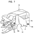
- the yarn joining device 13 integrally comprises the yarn tension adjusting device main body 6 composed of a plurality of constituent members (various yarn handling levers, a yarn joining main body, and the like) assembled together and including the attachment member 6a removably attached to the winding unit support main body 1, the other junction sections 4b of the three piping connectors 4 for receiving cleaning compressed air, the driven node (not shown in Figure 7 because it is disposed inside the main body section 6), that is, the other node of the transmission mechanism 5 comprising a gear for driving the various yarn handling levers or the like, and the bolts 10b, 10b of the two connection means 10, which are all disposed at predetermined positions of the yarn joining device 13.
- the yarn tension adjusting device main body 6 composed of a plurality of constituent members (various yarn handling levers, a yarn joining main body, and the like) assembled together and including the attachment member 6a removably attached to the winding unit support main body 1, the other junction sections 4b of the three piping connectors 4 for receiving cleaning compressed air, the driven no
- the attachment member 6a of the yarn joining device 13 has a notch section 19 formed therein and through which the one node 5a (see Figure 1) advances when the junction sections of the transmission mechanism 5 are connected together.
- the winding unit support main body 1 has the one junction sections 4a of the three piping connectors 4, the driving node 5a (see Figure 1), that is, the one node of the transmission mechanism 5, and the threaded holes 10a of the two connection means 10, which are all arranged at predetermined positions in an area in which the yarn joining device 13 is mounted.
- the junction or separation of each of the connectors 4, the connection and separation of the transmission mechanism 5, and the screwing and separation of the connection means 10 can be carried out simultaneously or in parallel.
- an origin fixing pin (not shown in the drawings) is attached to the driving node 5a of the transmission mechanism 5 for stopping the driving node 5a at an origin.
- the wax applying device 14 one type of the winding unit constituting device 2, integrally comprises the wax applying device main body 6 composed of a plurality of constituent members (a wax support member, a yarn guide member, and the like) assembled together and including the attachment member 6a removably attached to the winding unit support main body 1, the other junction 3b of the wiring connector 3, the other junction section 4b of the piping connector 4 for receiving cleaning compressed air, the driven node 5b, that is, the other node of the transmission mechanism 5 for pressing a wax open to drive it, the hole 9b of the positioning means 9, and the bolt 10b of the connection means 10, which are all disposed at predetermined positions of the wax applying device 14.
- the wax applying device main body 6 composed of a plurality of constituent members (a wax support member, a yarn guide member, and the like) assembled together and including the attachment member 6a removably attached to the winding unit support main body 1, the other junction 3b of the wiring connector 3, the other junction section 4b of the piping connector 4 for receiving cleaning compressed air, the driven node
- the winding unit support main body 1 has the one junction section 3a of the wiring connector 3, the driving node 5a, that is, the one node of the transmission mechanism 5, the pin 9a of the positioning means 9, and the threaded hole 10a of the connection means 10, which are all arranged at predetermined positions in an area in which the wax applying means 14 is mounted.
- the junction or separation of the connectors 3, 4, the connection and separation of the transmission mechanism 5, the fitting or separation of the positioning means 9, and the screwing and separation of the connection means 10 can be carried out simultaneously or in parallel.
- the yarn defect detecting device 15 one type of the winding unit constituting device 2, integrally comprises a yarn defect detecting device main body 6 composed of a plurality of constituent members (a yarn guide member, a detection member, and the like) assembled together and including the attachment member 6a removably attached to the winding unit support main body 1, the other junction section 3b of the wiring connector 3, the other junction section 4b of the connector 4 for piping for receiving cleaning compressed air, the hole 9b of the positioning means 9, and the bolt 10b of the connection means 10, which are all arranged at predetermined positions of the yarn defect detecting device 15.
- a yarn defect detecting device main body 6 composed of a plurality of constituent members (a yarn guide member, a detection member, and the like) assembled together and including the attachment member 6a removably attached to the winding unit support main body 1, the other junction section 3b of the wiring connector 3, the other junction section 4b of the connector 4 for piping for receiving cleaning compressed air, the hole 9b of the positioning means 9, and the bolt 10b of the connection means 10, which are
- the winding unit support main body 1 has the one junction section 3a of the wiring connector 3, the one junction section 4a of the piping connector 4, the pin 9a of the positioning means 9, and the threaded hole 10a of the connection means 10, which are all arranged at predetermined positions in an area in which the yarn defect detecting means 15 is mounted.
- the yarn defect detecting device 15 When the yarn defect detecting device 15 is moved in the arrow A direction relative to the attachment section 1a of the winding unit support main body 1 in order to assemble the winding unit 11 for the automatic winder or to inspect it for maintenance, the junction or separation of the connectors 3, 4, the fitting or separation of the positioning means 9, and the screwing and separation of the connection means 10 can be carried out simultaneously or in parallel.
- the drum cover device 16 one type of the winding unit constituting device 2, integrally comprises a drum cover device main body 6 composed of a plurality of constituent members (a cover, a traverse regulating guide, and the like) assembled together and including the attachment member 6a removably attached to the winding unit support main body 1, the other junction section 3b of the wiring connector 3, the other junction section 4b of the connector 4 for piping for receiving cleaning compressed air, the other junction section 4'b of the connector 4 for piping for receiving regulation guide-driving compressed air, the hole 9b of the positioning means 9, and the bolts 10b, 10b of the connection means 10, which are all arranged at predetermined positions of the drum cover device 16.
- a drum cover device main body 6 composed of a plurality of constituent members (a cover, a traverse regulating guide, and the like) assembled together and including the attachment member 6a removably attached to the winding unit support main body 1, the other junction section 3b of the wiring connector 3, the other junction section 4b of the connector 4 for piping for receiving cleaning compressed
- the winding unit support main body 1 has the one junction section 3a of the wiring connector 3, the one junction section 4a of the cleaning piping connector 4, one junction section (not shown in the drawings) of the connector 4 for the regulation guide-driving piping, the pin 9a of the positioning means 9, and the threaded hole 10a of the connection means 10, which are all arranged at predetermined positions in an area in which the drum cover device 16 is mounted.
- the junction or separation of the connectors 3, 4, the fitting or separation of the positioning means 9, and the screwing and separation of the connection means 10 can be carried out simultaneously or in parallel.
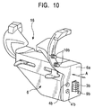
- a fluff suppressing device main body 6 composed of a plurality of constituent members (a disc unit, a press lever, a cutter, and the like) assembled together and including the attachment member 6a re
- the winding unit support main body 1 has the one junction section 3a of the wiring connector 3, the one junction section 4a of the piping connector 4, the driving node 5a, that is, the one node of the transmission mechanism 5 for driving the press lever, the driving node (not shown in the drawings), that is, the one node of the transmission mechanism 5 for driving the cutter, the pin 9a of the positioning means 9, and the threaded hole 10a of the connection means 10, which are all arranged at predetermined positions in an area in which the fluff suppressing device 17 is mounted.
- the junction or separation of the connectors 3, 4, the connection and separation of the transmission mechanism 5, 5, the fitting or separation of the positioning means 9, and the screwing and separation of the connection means 10 can be carried out simultaneously or in parallel.
- the yarn tension adjusting device 12 (the fluff suppressing device 17), the yarn joining device 13, the wax applying device 14, the yarn defect detecting device 15, and the drum cover device 16 each corresponding to the winding unit constituting device 2 can integrally use the other junction sections 3b, 4b of the connectors 3, 4 and the other node 5b of the transmission mechanism 5. Furthermore, when the yarn tension adjusting device 12 or the like corresponding to the winding unit constituting device 2 is attached to or removed from the winding unit support main body 1, the junction sections 3a, 3b (4a, 4b) of the connectors 3, 4 are joined together or mutually separated, respectively, and the nodes 5a, 5b of the transmission mechanism 5 are connected together or mutually separated, respectively.
- the entire winding unit for the automatic winder can be easily assembled or inspected for maintenance.
- the yarn tension adjusting device 12 or the like corresponding to the winding unit constituting device 2 can be assembled beforehand independently of the assembly of the entire winding unit for the automatic winder.
- specifications can be easily changed according to a user's request; for example, the fluff suppressing device 17 can be used instead of the yarn tension adjusting device 12.
- the winding unit 11 for the automatic winder comprises other winding unit constituting devices including a carrier guide (see Figure 12), a balloon breaker 22 (see Figure 13), a relay valve (see Figure 14), a suction mouth (see Figure 15), and a package holder 24 (see Figure 1).
- the carrier guide 21 integrally comprises a frame 21a, feeding link mechanisms 21b, 21c disposed in the frame 21a, and a driven node composed of control rods 21d, 21e for driving each link mechanism.
- the carrier guide 21 can be attached to or removed from the winding unit support main body 1 using bolts 10b, 10b corresponding to the connection means 10.
- the control rods 21d, 21e are connected to the driving node of the transmission mechanism (not shown in the drawings) provided in the winding unit support main body 1.
- the balloon breaker 22 integrally comprises a support plate 22a, a main body 22b located thereon for elevation and lowering, and an elevation controlling member 22 comprising an air cylinder for elevating or lowering the main body 22b.
- the balloon breaker 22 can be attached to the winding unit support main body 1 using the bolts 10b, 10b, ... Piping extended from the elevation controlling member 22c can be removably joined to the connector provided in the winding unit support main body 1.
- the relay pipe (see Figure 14) and the suction mouth (see Figure 15) are removably joined to tubular junction sections 26, 27, respectively, projected from the attachment section 1a of the winding unit support main body 1.
- winding unit 11 for the automatic winder various winding unit constituting devices are attached to the winding unit support main body 1 to constitute a winding unit U.
- the winding unit 11 uses a carrier guide 21 to guide a supply bobbin B loaded by a supply bobbin conveyor 28, to a predetermined unwinding position E.
- a yarn is unwound from the supply bobbin B at the unwinding position E, subsequently passed through the balloon breaker 22, the yarn tension adjusting device 12, the wax applying device 14, and the yarn defect detecting device 15, and then wound into a package P, which is rotated by a traverse drum 18.
- a suction mouth 24 for sucking ends of pieces of a cut yarn and a relay pipe 23 are pivoted to place the upper and lower yarns in the yarn joining device 13.
- An empty bobbin B' is ejected onto an empty bobbin conveyor 29 by means of the carrier guide 21. Piping and electric wiring to the winding unit constituting member 12 are threaded through the winding unit support main body 1 and connected to main pipe and wire of the base, respectively.
- the entire winding unit for the automatic winder can be easily assembled and the winding unit constituting device can be assembled beforehand separately from the assembly of the entire winding unit for the automatic winder.
- the winding unit for the automatic winder can be easily inspected for maintenance without the need to bringing the winding unit down toward the operation passage, thereby reducing maintenance and management costs of the winding unit for the automatic winder.
Landscapes
- Engineering & Computer Science (AREA)
- Textile Engineering (AREA)
- Replacing, Conveying, And Pick-Finding For Filamentary Materials (AREA)
- Tension Adjustment In Filamentary Materials (AREA)
- Winding Of Webs (AREA)
- Replacement Of Web Rolls (AREA)
- Spinning Or Twisting Of Yarns (AREA)
Abstract
Description
Claims (4)
- A winding unit for an automatic winder comprising winding unit constituting devices attached to a winding unit support main body, the winding unit being characterized in that said winding unit support main body comprises one of matching junction sections of a connector disposed at a predetermined position thereof, said winding unit constituting devices each comprise a plurality of constituent members assembled together and including an attachment member removably attached to said winding unit support main body as well as the other junction section of the connector disposed at a predetermined position thereof, the constituent members and the other junction section being integrated together, and when the attachment member of said winding unit constituting device is attached to or removed from said winding unit support main body, the junction sections of the connector are joined together or mutually separated, respectively.
- A winding unit for an automatic winder comprising winding unit constituting devices attached to a winding unit support main body, the winding unit being characterized in that said winding unit support main body comprises either a driving or a driven node of a transmission mechanism disposed at a predetermined position thereof, said winding unit constituting devices each comprise a plurality of constituent members assembled together and including an attachment member removably attached to said winding unit support main body as well as the other node of the transmission mechanism disposed at a predetermined position thereof, the constituent members and the other node being integrated together, and when the attachment member of said winding unit constituting device is attached to or removed from said winding unit support main body, the nodes of the transmission mechanism are connected together or mutually separated, respectively.
- A winding unit for an automatic winder comprising winding unit constituting devices attached to a winding unit support main body, the winding unit being characterized in that said winding unit support main body comprises one of matching junction sections of a connector disposed at a predetermined position thereof and either a driving or a driven node of a transmission mechanism disposed at a predetermined position thereof, said winding unit constituting devices each comprise a plurality of constituent members assembled together and including an attachment member removably attached to said winding unit support main body as well as the other junction section of the connector disposed at a predetermined position thereof and the other node of the transmission mechanism disposed at a predetermined position thereof, the constituent members and the other node being integrated together, and when the attachment member of said winding unit constituting device is attached to or removed from said winding unit support main body, the junction sections of the connector are joined together or mutually separated, respectively, and the nodes of the transmission mechanism are connected together or mutually separated, respectively.
- A winding unit for an automatic winder according to any one of claims 1 to 3, characterized in that two of said connectors are disposed each for pneumatic piping and for electric wiring, and when the winding unit constituting device is moved in one direction to attach or remove said winding unit support main body to or from said attachment member, the junction sections of the connector are joined together or mutually separated, respectively.
Applications Claiming Priority (2)
| Application Number | Priority Date | Filing Date | Title |
|---|---|---|---|
| JP29082199A JP4048661B2 (en) | 1999-10-13 | 1999-10-13 | Automatic winder winding unit |
| JP29082199 | 1999-10-13 |
Publications (3)
| Publication Number | Publication Date |
|---|---|
| EP1092666A2 true EP1092666A2 (en) | 2001-04-18 |
| EP1092666A3 EP1092666A3 (en) | 2002-06-19 |
| EP1092666B1 EP1092666B1 (en) | 2005-09-21 |
Family
ID=17760927
Family Applications (1)
| Application Number | Title | Priority Date | Filing Date |
|---|---|---|---|
| EP20000122016 Expired - Lifetime EP1092666B1 (en) | 1999-10-13 | 2000-10-10 | Winding unit for automatic winder |
Country Status (3)
| Country | Link |
|---|---|
| EP (1) | EP1092666B1 (en) |
| JP (1) | JP4048661B2 (en) |
| DE (1) | DE60022718T2 (en) |
Cited By (3)
| Publication number | Priority date | Publication date | Assignee | Title |
|---|---|---|---|---|
| WO2006018561A1 (en) * | 2004-07-27 | 2006-02-23 | Saint-Gobain Vetrotex France S.A. | Improvement made to a removable traversing device |
| EP2570375A3 (en) * | 2011-09-15 | 2015-11-25 | Murata Machinery, Ltd. | Yarn winding unit and yarn winding machine |
| CN106946093A (en) * | 2017-04-06 | 2017-07-14 | 海盐县通元弗斯特工艺品厂 | A kind of safe power equipment |
Family Cites Families (4)
| Publication number | Priority date | Publication date | Assignee | Title |
|---|---|---|---|---|
| YU179568A (en) * | 1967-08-17 | 1973-10-31 | Elitex Z Textil Strojirenst Ge | Automatska masina za sukanje |
| JPS52107344A (en) * | 1976-03-01 | 1977-09-08 | Murata Machinery Ltd | Single spindle type automatic winder |
| CH660872A5 (en) * | 1982-09-24 | 1987-05-29 | Mayer Textilmaschf | Automatic winding machine |
| DE3624904A1 (en) * | 1986-07-23 | 1988-01-28 | Schlafhorst & Co W | AUTOMATIC CROSS REEL WINDING MACHINE |
-
1999
- 1999-10-13 JP JP29082199A patent/JP4048661B2/en not_active Expired - Fee Related
-
2000
- 2000-10-10 EP EP20000122016 patent/EP1092666B1/en not_active Expired - Lifetime
- 2000-10-10 DE DE2000622718 patent/DE60022718T2/en not_active Expired - Lifetime
Cited By (4)
| Publication number | Priority date | Publication date | Assignee | Title |
|---|---|---|---|---|
| WO2006018561A1 (en) * | 2004-07-27 | 2006-02-23 | Saint-Gobain Vetrotex France S.A. | Improvement made to a removable traversing device |
| US7614580B2 (en) | 2004-07-27 | 2009-11-10 | Saint-Gobain Technical Fabrics Europe | Removable traversing device |
| EP2570375A3 (en) * | 2011-09-15 | 2015-11-25 | Murata Machinery, Ltd. | Yarn winding unit and yarn winding machine |
| CN106946093A (en) * | 2017-04-06 | 2017-07-14 | 海盐县通元弗斯特工艺品厂 | A kind of safe power equipment |
Also Published As
| Publication number | Publication date |
|---|---|
| JP2001106432A (en) | 2001-04-17 |
| DE60022718T2 (en) | 2006-07-06 |
| EP1092666A3 (en) | 2002-06-19 |
| JP4048661B2 (en) | 2008-02-20 |
| EP1092666B1 (en) | 2005-09-21 |
| DE60022718D1 (en) | 2005-10-27 |
Similar Documents
| Publication | Publication Date | Title |
|---|---|---|
| IT9048336A1 (en) | MAINTENANCE SURVEILLANCE EQUIPMENT FOR AUTOMATIC WINDER. | |
| JPH0325310B2 (en) | ||
| JPH0124706B2 (en) | ||
| FR2537168A1 (en) | WOVEN WORK WITHOUT A SHUTTLE COMPRISING A MEANS FOR REMOVING, FROM THE CROWD, DEFECTIVE WIRES OF FRAME | |
| EP1092666B1 (en) | Winding unit for automatic winder | |
| IT8249601A1 (en) | PNEUMATIC DEVICE FOR SPLICING TEXTILE THREADS | |
| EP0534637A1 (en) | Transfer tail holding device | |
| JP7009115B2 (en) | A suction device for sucking the thread end of the thread wound in the take-up package, and a method for monitoring the suction channel portion of the suction device by sensing. | |
| DE60025118T2 (en) | Automatic winding machine | |
| JP2007326720A (en) | Take-up unit of automatic winder | |
| JP2018177529A (en) | Work unit of textile machine for manufacturing cross winding package | |
| CN111620158B (en) | Automatic roll changing and receiving system and method for disposable sanitary product production equipment | |
| CN109906004B (en) | Automatic wiring robot | |
| KR102281216B1 (en) | Dummy cable automatic welding device and welding method | |
| CN111620159B (en) | Automatic roll changing and receiving system and method for flexible coiled material | |
| CN110842426A (en) | Portable intelligent welding robot | |
| IT8222652A1 (en) | Procedure for resuming the spinning process after a fault in the automatic reel change or when changing the yarn count in open end spinning machines and device for carrying out this process | |
| JPS6228624Y2 (en) | ||
| KR102934710B1 (en) | A Winding System of Stranded Wire | |
| KR20220056996A (en) | Wire feeding system | |
| JP4179436B2 (en) | Automatic winder winding unit | |
| CN218263042U (en) | Paper tape conveying device for assisting sewing | |
| JPH0218031Y2 (en) | ||
| JPH023469Y2 (en) | ||
| JPH0333704Y2 (en) |
Legal Events
| Date | Code | Title | Description |
|---|---|---|---|
| PUAI | Public reference made under article 153(3) epc to a published international application that has entered the european phase |
Free format text: ORIGINAL CODE: 0009012 |
|
| AK | Designated contracting states |
Kind code of ref document: A2 Designated state(s): AT BE CH CY DE DK ES FI FR GB GR IE IT LI LU MC NL PT SE |
|
| AX | Request for extension of the european patent |
Free format text: AL;LT;LV;MK;RO;SI |
|
| PUAL | Search report despatched |
Free format text: ORIGINAL CODE: 0009013 |
|
| AK | Designated contracting states |
Kind code of ref document: A3 Designated state(s): AT BE CH CY DE DK ES FI FR GB GR IE IT LI LU MC NL PT SE |
|
| AX | Request for extension of the european patent |
Free format text: AL;LT;LV;MK;RO;SI |
|
| 17P | Request for examination filed |
Effective date: 20020930 |
|
| AKX | Designation fees paid |
Designated state(s): DE IT |
|
| 17Q | First examination report despatched |
Effective date: 20030603 |
|
| GRAP | Despatch of communication of intention to grant a patent |
Free format text: ORIGINAL CODE: EPIDOSNIGR1 |
|
| RIN1 | Information on inventor provided before grant (corrected) |
Inventor name: NAKAMURA, YOUICHI,MURATA KIKAI SHATAKU B-208-GOU Inventor name: KONO, SATORU,MURATA KIKAI SHATAKU B-201 |
|
| GRAS | Grant fee paid |
Free format text: ORIGINAL CODE: EPIDOSNIGR3 |
|
| GRAA | (expected) grant |
Free format text: ORIGINAL CODE: 0009210 |
|
| AK | Designated contracting states |
Kind code of ref document: B1 Designated state(s): DE IT |
|
| REF | Corresponds to: |
Ref document number: 60022718 Country of ref document: DE Date of ref document: 20051027 Kind code of ref document: P |
|
| PLBE | No opposition filed within time limit |
Free format text: ORIGINAL CODE: 0009261 |
|
| STAA | Information on the status of an ep patent application or granted ep patent |
Free format text: STATUS: NO OPPOSITION FILED WITHIN TIME LIMIT |
|
| 26N | No opposition filed |
Effective date: 20060622 |
|
| REG | Reference to a national code |
Ref country code: DE Ref legal event code: R082 Ref document number: 60022718 Country of ref document: DE Representative=s name: PATENTANWAELTE WEICKMANN & WEICKMANN, DE Ref country code: DE Ref legal event code: R082 Ref document number: 60022718 Country of ref document: DE Representative=s name: WEICKMANN & WEICKMANN PATENTANWAELTE - RECHTSA, DE Ref country code: DE Ref legal event code: R082 Ref document number: 60022718 Country of ref document: DE Representative=s name: WEICKMANN & WEICKMANN PATENT- UND RECHTSANWAEL, DE |
|
| PGFP | Annual fee paid to national office [announced via postgrant information from national office to epo] |
Ref country code: DE Payment date: 20191021 Year of fee payment: 20 |
|
| PGFP | Annual fee paid to national office [announced via postgrant information from national office to epo] |
Ref country code: IT Payment date: 20191028 Year of fee payment: 20 |
|
| REG | Reference to a national code |
Ref country code: DE Ref legal event code: R071 Ref document number: 60022718 Country of ref document: DE |