EP1092513A2 - Graphic display apparatus for robot system - Google Patents
Graphic display apparatus for robot system Download PDFInfo
- Publication number
- EP1092513A2 EP1092513A2 EP00308932A EP00308932A EP1092513A2 EP 1092513 A2 EP1092513 A2 EP 1092513A2 EP 00308932 A EP00308932 A EP 00308932A EP 00308932 A EP00308932 A EP 00308932A EP 1092513 A2 EP1092513 A2 EP 1092513A2
- Authority
- EP
- European Patent Office
- Prior art keywords
- robot
- model
- dimension
- machine
- displayed
- Prior art date
- Legal status (The legal status is an assumption and is not a legal conclusion. Google has not performed a legal analysis and makes no representation as to the accuracy of the status listed.)
- Granted
Links
Images



Classifications
-
- B—PERFORMING OPERATIONS; TRANSPORTING
- B25—HAND TOOLS; PORTABLE POWER-DRIVEN TOOLS; MANIPULATORS
- B25J—MANIPULATORS; CHAMBERS PROVIDED WITH MANIPULATION DEVICES
- B25J9/00—Program-controlled manipulators
- B25J9/16—Program controls
- B25J9/1656—Program controls characterised by programming, planning systems for manipulators
- B25J9/1671—Program controls characterised by programming, planning systems for manipulators characterised by simulation, either to verify existing program or to create and verify new program, CAD/CAM oriented, graphic oriented programming systems
-
- G—PHYSICS
- G05—CONTROLLING; REGULATING
- G05B—CONTROL OR REGULATING SYSTEMS IN GENERAL; FUNCTIONAL ELEMENTS OF SUCH SYSTEMS; MONITORING OR TESTING ARRANGEMENTS FOR SUCH SYSTEMS OR ELEMENTS
- G05B2219/00—Program-control systems
- G05B2219/30—Nc systems
- G05B2219/35—Nc in input of data, input till input file format
- G05B2219/35314—Display workpiece and machine, chuck, jig, clamp, tool
-
- G—PHYSICS
- G05—CONTROLLING; REGULATING
- G05B—CONTROL OR REGULATING SYSTEMS IN GENERAL; FUNCTIONAL ELEMENTS OF SUCH SYSTEMS; MONITORING OR TESTING ARRANGEMENTS FOR SUCH SYSTEMS OR ELEMENTS
- G05B2219/00—Program-control systems
- G05B2219/30—Nc systems
- G05B2219/36—Nc in input of data, input key till input tape
- G05B2219/36071—Simulate on screen, if operation value out of limits, edit program
-
- G—PHYSICS
- G05—CONTROLLING; REGULATING
- G05B—CONTROL OR REGULATING SYSTEMS IN GENERAL; FUNCTIONAL ELEMENTS OF SUCH SYSTEMS; MONITORING OR TESTING ARRANGEMENTS FOR SUCH SYSTEMS OR ELEMENTS
- G05B2219/00—Program-control systems
- G05B2219/30—Nc systems
- G05B2219/36—Nc in input of data, input key till input tape
- G05B2219/36315—Library for shapes of tool holders, fixtures, chucks
Definitions
- the present invention relates to a graphic display apparatus for robot systems used in off-line programming of a robot, in which a model of the robot displayed on a screen is caused to move in animation form.
- a motion simulation for moving the 3-D model of the robot in animation based on the teach program is useful for correction of a robot motion programming by checking the robot motion and detecting a relation between the robot motion and a peripheral device, a machine and a part (workpiece) relating to the robot operation.
- one embodiment of the graphic display apparatus for a robot system comprises: means for displaying and arranging a 3-D model of a robot on a display screen to cause the displayed model to move in animation on the screen; means for storing the 3-D model of the robot and one or more 3-D models of a peripheral equipment, a machine or a part, which is used in a system using the robot; and means for selecting one or more 3-D models stored in the storing means on the display screen.
- the above graphic display apparatus for a robot system may comprise means for adjusting a dimension of the 3-D model, selected by the selecting means, on the screen.
- the 3-D model of the robot and whose dimension was adjusted by the adjusting means, or the 3-D model of the robot and the 3-D model of peripheral equipment, a machine or a part, which was selected by the selecting means, and whose dimensions were adjusted by the adjusting means, are displayed and arranged on the display screen, so that at least a part of the system using the robot is approximated.
- the graphic display apparatus for a robot system comprises: means for displaying and arranging a 3-D model of a robot on a display screen to cause the displayed model to move in animation on the screen; a first storing means for storing the 3-D model of the robot: a second storing means for storing one or more 3-D models of a peripheral equipment, a machine or a part, which is used in a system using the robot; means for selecting one or more 3-D models stored in the second storing means on the display screen; and means for adjusting a dimension of the 3-D model selected by the selecting means, on the screen.
- the 3-D model of the robot, and the 3-D model of the peripheral equipment, the machine or the part, which was selected by the selecting means, and whose dimension was adjusted by the adjusting means, are displayed and arranged on the display screen, so that at least a part of the system using the robot is approximated.
- the graphic display apparatus for robot system further comprises means for displaying, on the screen in animation, the robot motion corresponding to at least a portion of a robot program.
- 3-D models of the peripheral equipment, the machine or the part are classified by kinds, a plurality of different types are displayed on the screen for each of the classified kinds, and a 3-D model is selected from the displayed types.
- the graphic display apparatus for robot system further comprises means for adding a 3-D model of the peripheral equipment, the machine or the part of the robot in the storing means so as to meet a requirement of a newly added peripheral equipment, machine or part.
- the graphic display apparatus for robot system further comprises a robot controller and means for sending and receiving information, and the shape of the 3-D model of the peripheral equipment, the machine or the part is adjusted based on position data.
- These data are obtained by moving the tool center point (TCP) of an actual robot to a plurality of positions which constitute characteristic features of an actual peripheral equipment, machine or the part corresponding to the 3-D model of the peripheral equipment, the machine or the part and then detecting these positions, or obtained by mounting a sensor on an actual robot and detecting the positions which constitute characteristic features of an actual peripheral equipment, machine or the part corresponding to the 3-D model of the peripheral equipment, the machine or the part.
- TCP tool center point
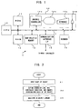
- Fig.1 is a block diagram showing an essential portion of a graphic display apparatus 1 for a robot system according to one embodiment of the present invention.
- the graphic display apparatus 1 for the robot system includes a processor 10. Connected to the processor 10 through a bus 17 are a ROM 11, a RAM 12, a battery-protected nonvolatile memory 13 comprising a CMOS memory, a display unit 14, a communication interface 15 connected to a robot controller and the like through a line of communication, a scanner 16 for capturing image, and the like.
- the display unit 14 includes a graphic control circuit 14a, display means 14b comprising a liquid crystal display or a CRT, a keyboard 14c, a mouse 14d and the like.
- the graphic control circuit 14a, the keyboard 14c and the mouse 14d are connected to the bus 17.
- 3-D models of various peripheral devices, machines and parts relating to robot motions are stored in advance in the nonvolatile memory 13.
- the examples of the various peripheral devices, machines and parts relating to robot motion of which 3-D models are created are an automobile and workpieces such as machine parts, which are directly operated by a robot, a peripheral device such as a tool automatic exchanging apparatus for automatically exchanging a tool of an end effector mounted to a tip of a robot arm, an end effector mounted to the tip of a robot arm, a jig, and a robot itself.
- a robot, peripheral devices, machines and parts relating to robot motion are generally called "object”.
- Peripheral devices, machines and parts are classified by kinds, and 3-D models thereof are stored in the nonvolatile memory 13.
- these workpieces are divided into two classes, i.e., "workpiece 1" and "workpiece 2", and a 3-D model of each workpiece (part) is stored.
- One class of "device” is allocated to machines such as peripheral devices.
- Machine end effectors mounted to the tip of a robot arm are classified into "spotgun” for spot guns, “arctool” for arc tools, “handtool” for hand tools, and “tool” for other tools.
- classes of "jig” for jigs and "robot” for robots are also prepared, and the 3-D models of the objects are classified by kinds and stored.
- Fig.2 is a flowchart showing an input procedure of shapes of the 3-D models of objects (peripheral devices, machines and parts). If an object 3-D model register mode is selected using the keyboard 14c, the processor 10 starts the processing shown in Fig.2.
- a message urging an operator to input a class and name of an object and a name and shape of a part is displayed. Then the operator, according to the message, inputs a class and name of an object and further a name of a part (if there are a plurality of parts for the object). And the operator inputs the shape of the object or part using a modeling system in a form defined by a polyhedron as in the conventional manner (step A1).
- the operator When inputting of the shape is completed, the operator inputs a definition of a dimension line with respect to the object and a constraint condition to be considered when the shape of the object is subjected to change (step A2).
- Definition of a dimension line is carried out by selecting an edge line at a position where the dimension of the object can be changed and setting a length of a leader line with respect to the dimension line and a color of the dimension line.
- an origin of coordinate systems is set at the apex P1
- the direction advancing from the apex P1 to the apex P4 is Y axis plus direction
- the direction advancing from the apex P1 to the apex P2 is X axis plus direction
- the direction advancing from the apex P1 to the apex P5 is Z axis minus direction.
- the shape of the the object 3-D model 30 can change but it shape change is limited to only X and Y axes direction, not changing in Z axis direction.
- dimension lines are defined for edge lines which can change its length.
- Fig. 9 shows an example in which four dimension lines are defined between the apexes P2 and P3, between the apexes P1 and P2, between the apexes P4 and P11, and between the apexes P11 and P9.
- a constraint condition which stipulates how the shape of an object has to be changed when a dimension of the object, set in advance with respect to the object, is changed is set.
- a change in shape of the object means a change in a distance between the apexes. Accordingly, in this case, a constraint condition providing a mode of change in the position of the apexes of which coordinates are to be changed when the dimension is changed in association with the change of the shape.
- the constraint condition, in creating a shape, associated with the change in the length of the dimension line between the apex P1 and the apex P2 or change of the X axis coordinate value of the apex P2 provides that the X axis coordinate values of the apexes P3, P7 and P6 has to be changed.
- a constraint condition providing that the X axis coordinate value of the apex P2 and the X axis coordinate values of the apexes P3, P7 and P6 are equal to each other.
- a condition providing that the X axis coordinate value of the apex P2 is greater than the X axis coordinate value of the apex P1 is set.
- the constraint condition associated with change in the dimension between the apexes P2 and P3 provides that the Y axis coordinate value of the apex P3 is equal to the Y axis coordinate values of the apexes P7, P9 and P10 is set.
- the coordination check condition a condition providing that the Y axis coordinate value of the apex P3 is greater than the Y axis coordinate value of the apex P2 is set.
- the constraint condition associated with change in the dimension between the apexes P4 and P11 provides that the X axis coordinate value of the apex P11 is equal to the X axis coordinate values of the apexes P9, P10 and P12 is set.
- a condition that the X axis coordinate value of the apex P11 is greater than the X axis coordinate value of the apex P4 is set.
- the constraint condition associated with change in the dimension between the apexes P11 and P9 provides that the Y axis coordinate value of the apex P9 is equal to the Y axis coordinate values of the apexes P3, P7 and P10 is set.
- a condition that the Y axis coordinate value of the apex P9 is greater than the Y axis coordinate value of the apex P11 is set.
- the processor 10 stores, in the nonvolatile memory 13, data for specifying the object shape and data for defining the dimension lines as the object library, based on the inputted data (step A3).
- the object name object identifier
- phase data geometric data
- dimension line data dimension line data
- constraint condition data coordination check condition data
- Phase data such as name of a part (object ID), apex ID, and edge line ID, and relation between the phase data are stored. These phase data is obtained from the polyhedron shape of the 3-D model which is analogous to the object created in step A1.
- An edge line formula with respect to the edge line ID stored as a phase data, a surface formula with respect to a surface ID, 3-D position data with respect to an apex ID are stored as the geometric data.
- the geometric data is also obtained from the polyhedron shape of the 3-D model which is analogous to the object created in step A1.
- the dimension line data set in step A2 is stored as dimension line data, and this data is stored in the following manner:
- dimension line data set in step A2 is:
- "dim” is a code defining the dimension line.
- Test2 is an object ID expressing an object name.
- Text4 is a part ID expressing a part name.
- the next "1" and “2" represent the apexes P1 and P2, respectively.
- the arrangement of two apexes in the dimension line means the coordinate value of the former apex is not changed while the coordinate value (in the direction of command) of the latter apex is changed when a length of a dimension line is changed. In the above example, it means that the coordinate value of the apex P1 is not changed while the coordinate value of the apex P2 is changed.
- the next "1" represents a direction of the dimension leader line.
- the constraint condition set in step A2 is stored in the form of following data:
- "moveabs” is a code of the constraint condition.
- "test2” and “Text4" are the object ID and the part ID, respectively.
- the next “2, 0, 3, 0” indicates apex P2, direction 0, apex P3, direction 0", respectively.
- "0" is X axis direction
- "1" is Y axis direction
- "2" is Z axis direction.
- "2, 0, 3, 0" means that the X axis coordinate value of the apex P2 is equal to the X axis coordinate value of the apex P3.
- the coordination check data is stored in the following manner:
- the above formula means that the coordination is fulfilled only when the value of the coordinate axis specified by the first "direction" of the apex specified by the first "apex ID" is greater than the value of the coordinate axis specified by the second "direction” of the apex specified by the second "apex ID".
- the direction "0" indicates X axis direction, "1” indicates Y axis direction and "2" indicates Z axis direction.
- checkifgtops is a code of the coordination check
- the latter portion "2, 0, 1, 0" indicates that in the case where the value of the X axis coordinate of the apex P2 is greater than the value of the X axis coordinate of the apex P1, it is determined that the coordination is fulfilled and in other case, it is not determined so.
- the dimension line data, the constraint condition data and the coordination check data are stored in the object library in the following manner:
- the objects such as peripheral devices, machines and parts, which relate to the robot motion, are classified.
- the shapes, the dimension lines, the constraint condition and the coordination check data of the object are inputted as described above.
- the phase data, the geometric data, the dimension line data, the constraint condition data and the coordination check data, which are necessary for specifying the shape of an object are stored in the nonvolatile memory 13 as an object library.
- a reduced scale image of the object shape for menu display is formed based on the inputted object shape and is stored for the menu.
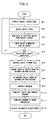
- FIG.3 is a flowchart showing a procedure of the monitoring procedure according to the embodiment.
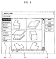
- the processor 10 displays the object library menu on the display means 14b of the display unit 14 as shown in Fig.8 (step B1).
- a first item "workpiece 1" is selected, and a shape menu of object (parts) 3-D models registered in the "workpiece 1" is displayed in the shape menu display column 21 in the central portion of the screen.
- the operator selects a class of the object to be inputted from the class column 20 using the mouse 14 or a pointing device such as a cursor.
- the shape menu of the 3-D model of the object corresponding to the selected class item is displayed in the shape menu display column 21.
- a shape menu of 3-D models of workpieces (parts) registered as the "workpiece 1" in this class is displayed in the shape menu display column 21.
- a class item "spotgun” is selected, a shape menu of 3-D models of registered spot guns is displayed in the shape menu display column 21.
- a class item "robot” is selected, a shape menu of 3-D models of registered robots is displayed in the shape menu display column 21.
- the operator selects a class item to have the shape menu of 3-D models of the object relating to the item displayed, operates a scroll bar 22 to scroll a screen of the shape menu display column 21, and selects a menu screen corresponding to a shape of the object to be inputted using the mouse 14d or the like.
- a scroll bar 22 to scroll a screen of the shape menu display column 21, and selects a menu screen corresponding to a shape of the object to be inputted using the mouse 14d or the like.
- an object name "test2" of the "workpiece1" has been selected, and the selected object ID is displayed in the selection column 23 (step B2).
- the processor 10 reads data of the selected object 3-D model data from the object library stored in the nonvolatile memory 13 and stores the data in the RAM 12. Then the processor 10 displays a shape of the selected object 3-D model based on the phase data and geometric data of the object 3-D model, and further displays dimension lines and dimension leader lines based on the dimension line data (step B3). Further, the processor 10 calculates a length of an edge line corresponding to the set dimension line data using the apex coordinate position data in the stored geometric data, and displays the length of the edge line in the dimension line inputting column corresponding to the dimension line data, as shown in Fig.9.
- a reference numeral 30 represents a shape of a selected object 3-D model
- a reference numeral 31 represents numeral value inputting columns which can change the shape or dimension of the displayed object 3-D model.
- Fig.9 illustrate the symbols of the apexes "P1" to "P12", these symbols are not displayed on the screen in practice.
- the data of these apexes P1 to P12 is stored as an object library.
- displayed are lengths of dimension lines, or lengths of the distance between apexes, obtained from the shape of the object created when the object library was formed.
- the operator inputs a value corresponding to the dimension of the actual object which is actually used.
- the operator selects one of numerical value inputting columns 31 using the mouse 14d, colors of the dimension line and dimension leader line corresponding to the selected column 31 are changed, so that the operator can discriminate the edge line selected. For example, in Fig.9, if the column of "dimension 1" is selected, an edge line between the apexes P2 and P3 corresponding to this column is selected and colors of the dimension line showing its length and dimension leader line are changed. If the operator inputs an actual dimension of the edge line of object of which color has been changed, this inputted dimension is displayed in the corresponding column 31.
- the position of an apex determined by the length of a dimension line which was inputted earlier does not coincide with the position of the same apex determined by the length of another dimension line which was inputted lately
- the position of the apex determined based on the length of a dimension line which was inputted lately takes precedence. For example, if, after input of the numerical value of a dimension line (dimension 1) between the apexes P2 and P3, the numerical value of a dimension line (dimension 4) between the apexes P11 and P9 is inputted, then Y axis coordinate value of the apexes P3, P7, P9, P10 has to be the same value. However, if these values are not same, the Y axis coordinate values of the related apexes are changed based on the dimension (dimension 4) between the apexes P11 and P9.
- the processor 10 calculates a coordinate position of each apex based on the constraint condition data stored as data of object 3-D model, and changes a coordinate value of the apex, which corresponds to the data of the object 3-D model which was read from the object library and is stored in the RAM 12.
- a displayed shape is also changed based on the newly inputted dimension value (step B4).
- steps B1 to B5 are carried out for the robot and all other objects relating the robot motion.
- Data of 3-D model of a robot body, and data of 3-D models of peripheral devices, machines and parts which relate to the robot motion are read from the object library.
- the dimensions of the object 3-D model data, which is to be changed, are changed according to the above-described procedure, while the dimensions which is to be remained without change are stored in the RAM 12 as they are after being read out of the object library.
- step B5 When all the object 3-D model data relating to the robot motion are read and the dimension changing procedure is completed (step B5), a procedure for arranging the 3-D model of an object in a work cell where the robot system is disposed is carried out (step B6).
- a plan view of a layout of the work cell is read and displayed (step C1).
- a plan view may be read, through the communication interface 15, from a plan view file which was generated using a CAD or the like and stored.
- a plan view may be read from storing medium such as a floppy disc through a driver (not shown).
- a layout plan view drawn in a paper may be read using the scanner 16. Accordingly, a plan view of the layout of the work cell can be read using any one of the three methods and displayed on the display means 14b of the display unit.
- Fig. 10 shows one example of the plan view of the layout of the work cell, showing a plan views of the layout of the robot, table, workpiece and the like when the robot carries out the arc welding. Such a plan view is read and displayed on the display means 14b.
- three points on a wire frame of the displayed plan view are designated to form a surface on an object image.
- three points on the wire frame are designated and a closed polygon including the three points is searched. If a closed polygon is found by the search, a surface is formed by this polygon (step C2).
- the operator inputs the object definition command when defining the object on the plan view, while the operator inputs an object arranging command when arranging the 3-D model which had bee read from the object library and of which dimension has been adjusted, (step C3).
- the operator designates a surface formed on the plan view and inputs a value of the Z axis coordinate which is the height direction.
- the designated surface is lifted by the designated value in the Z axis direction.
- this coordinate value relating to the designated surface lifted is stored (step C4).
- a shape of the lifted surface is modified (step C5), thus completing this procedure.
- a surface formed on the plan view is designated, and the name of the object (object ID) of which 3-D model is to be arranged is inputted on the surface (step C6).
- the processor 10 causes the 3-D model of the designated object to move to the designated surface position (step C7). If definitions are to be carried out for a plurality of objects or arrangement of models are to be carried out for a plurality of objects, the procedures in steps C3 to C7 are repeated.
- step C7 When arrangement of the 3-D models of the objects in the work cell is completed, the procedure returns to Fig.3, and shape changing processing for the object 3-D model is carried out based on information from outside (step C7).
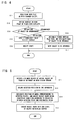
- Fig.5 is a flowchart showing shape changing processing for the object 3-D model shape.
- TCP tool center point
- the positions of the four or more points which form physical features of the actual object are detected using the sensor (step D1).
- the position data of the detected four or more points are uploaded to the graphic display apparatus for robot system 1 (step D2).
- the graphic display apparatus for robot system 1 designates the positions of the object 3-D models corresponding to the positions of the received four or more points, obtains a deviation between the positions of the detected points and the positions on the designated 3-D model, and adjusts the positions of each apex of the 3-D model, using the above-described constraint condition, so that the coordinate position of the designated point corresponds to the position of the detected point (step D3).
- step D4 the phase data, the geometric data, the dimension line data and the like stored in the RAM 12 are changed and the shape of the object 3-D model to be displayed on the display means 14b are also changed (step D4), so that the shapes of the displayed object 3-D models may coincide with the shape of the actual object. Then, this shape changing processing for the object 3-D model is completed.
- step B8 rearrangement processing for the 3-D model is carried out based on information from outside (step B8).
- This processing is carried out for correcting a deviation between the arrangement position of the object 3-D model and that of the actual object. This processing is carried out according to the procedure shown in Fig.6 or 7.
- the tool center point (TCP) mounted to the tip of a robot arm is caused to move and touching up (positioning) by the TCP is carried out on three or more points of the actual object.
- Information on the points touched up is transmitted to the graphic display apparatus for robot system 1 through a communication line (steps E1 and E2).
- the graphic display apparatus obtains a relative position of the object with respect to the robot from the received positions of the three points (step E3) and change the layout of the object 3-D model on the display screen based on the obtained relative position (step E4).
- a position and a posture of the object are obtained by the vision sensor, and the obtained position and the posture are transmitted to the graphic display apparatus 1 (steps F1 and F2).
- the graphic display apparatus 1 obtains a relative position of the object with respect to the robot based on the received position and the posture (step F3), and change the layout of the object 3-D model on the display screen based on the relative position obtained in this manner (step E4).
- a motion program of the robot is generated in the conventional manner (step B9) and the motion program is then verified by carrying out a simulation of the motion program, moving the robot 3-D model displayed on the screen in animation in the conventional manner. Then the motion program is modified if required so. In this manner, the motion program is completed (step B10).
- the motion program thus generated is downloaded to the robot controller through the communication interface 15 and the communication line (step B11).
- the robot controller executes the downloaded motion program (step B12).
- one standard type (shape) of robot is stored in advance for each kinds of robots in the object library in the form of a 3-D model.
- a robot 3-D model stored in the object library is selected in accordance with a kind or type (shape) of a robot to be used, and the dimensions of the selected model are set to form a 3-D model of the actual robot to be used.
- a 3-D model of the robot to be used may be directly read from the object library where the 3-D model of the robot has been stored, without newly creating the 3-D model of the robot.
- a 3-D model of the newly requested object is added to the object library according to the processing shown in Fig.2 so as to cope with the change of a robot, a peripheral device, a machine or a part (workpiece).
Landscapes
- Engineering & Computer Science (AREA)
- Robotics (AREA)
- Mechanical Engineering (AREA)
- Numerical Control (AREA)
- Manipulator (AREA)
Abstract
Description
Claims (10)
- A graphic display apparatus for a robot system comprising:means for displaying and arranging a 3-D model of a robot on a display screen to cause the displayed model to move in animation on the screen;means for storing the 3-D model of the robot and one or more 3-D models of a peripheral equipment, a machine or a part, which is used in a system using the robot; andmeans for selecting one or more 3-D models stored in said storing means on the display screen; whereinthe 3-D model of the robot, or the 3-D model of the robot and the 3-D model of a peripheral equipment, a machine or a part, which was selected by said selecting means, are displayed and arranged on the display screen, so that at least a part of the system using the robot is approximated.
- A graphic display apparatus for a robot system comprising:means for displaying and arranging a 3-D model of a robot on a display screen to cause the displayed model to move in animation on the screen;means for storing the 3-D model of the robot and one or more 3-D models of a peripheral equipment, a machine or a part, which is used in a system using the robot; andmeans for selecting one or more 3-D models stored in said storing means on the display screen; andmeans for adjusting a dimension of the 3-D model, selected by said selecting means, on the screen;
whereinthe 3-D model of the robot whose dimension was adjusted by said adjusting means, or the 3-D model of the robot and the 3-D model of a peripheral equipment, a machine or a part, which was selected by said selecting means, and whose dimensions were adjusted by said adjusting means, are displayed and arranged on the display screen, so that at least a part of the system using the robot is approximated. - A graphic display apparatus for robot system comprising:means for displaying and arranging a 3-D model of a robot on a display screen to cause the displayed model to move in animation on the screen;a first storing means for storing the 3-D model of the robota second storing means for storing one or more 3-D models of a peripheral equipment, a machine or a part, which is used in a system using the robot;means for selecting one or more 3-D models stored in said second storing means on the display screen; andmeans for adjusting a dimension of the 3-D model selected by said selecting means, on the screen;
whereinthe 3-D model of the robot, and a 3-D model of the peripheral equipment, the machine or the part, which was selected by said selecting means, and whose dimensions were adjusted by said adjusting means, are displayed and arranged on the display screen, so that at least a part of the system using the robot is approximated. - The graphic display apparatus for a robot system according to claim 3, wherein when the dimension of the 3-D model selected by said selecting means is adjusted by said adjusting means, coordination among the numerical values of a plurality of position data which constitute the 3-D model concerned is considered.
- The graphic display apparatus for a robot system according to claim 3, further comprising a storing means for a storing constraint condition which stipulates the coordination among numerical values of a plurality of position data which constitute each 3-D model stored in the second storing means, wherein when the dimension of the 3-D model selected by said selecting means is adjusted by said adjusting means, coordination among the numerical values of a plurality of position data which constitute the 3-D model is considered using the constraint condition stored in said constraint condition storing means.
- The graphic display apparatus for a robot system according to any preceding claim, further comprising means for displaying, on the screen, the robot motion corresponding to at least a part of a robot program, in animation.
- The graphic display apparatus for a robot system according to any preceding claim, wherein 3-D models of said peripheral equipment, said machine or said part are classified by kinds, a plurality of different types are displayed on the screen for each of the classified kinds, and a 3-D model is selected from among the displayed types.
- The graphic display apparatus for a robot system according to any preceding claim, further comprising means for adding a 3-D model of the peripheral equipment, the machine or the part of the robot in said storing means.
- The graphic display apparatus for a robot system according to any preceding claim, further comprising means for sending information to and receiving information from a robot controller; wherein the shape of the 3-D model of the peripheral equipment, the machine or the part is adjusted based on position data which forms a physical feature of the actual peripheral equipment, the machine or the part, sent from the robot controller through said information sending and receiving means.
- The graphic display apparatus for a robot system according to any preceding claim, wherein a plan view of the layout of an operation system using a robot is displayed on the display screen and the 3-D model of the peripheral equipment, the machine or the part is arranged on the display screen in correspondence with the layout, thereby allowing carrying out of modelling of a production system using the robot.
Applications Claiming Priority (2)
| Application Number | Priority Date | Filing Date | Title |
|---|---|---|---|
| JP28950899 | 1999-10-12 | ||
| JP28950899A JP3537362B2 (en) | 1999-10-12 | 1999-10-12 | Graphic display device for robot system |
Publications (3)
| Publication Number | Publication Date |
|---|---|
| EP1092513A2 true EP1092513A2 (en) | 2001-04-18 |
| EP1092513A3 EP1092513A3 (en) | 2004-04-07 |
| EP1092513B1 EP1092513B1 (en) | 2006-01-25 |
Family
ID=17744185
Family Applications (1)
| Application Number | Title | Priority Date | Filing Date |
|---|---|---|---|
| EP00308932A Expired - Lifetime EP1092513B1 (en) | 1999-10-12 | 2000-10-11 | Graphic display apparatus for robot system |
Country Status (4)
| Country | Link |
|---|---|
| US (1) | US7002585B1 (en) |
| EP (1) | EP1092513B1 (en) |
| JP (1) | JP3537362B2 (en) |
| DE (1) | DE60025683T2 (en) |
Cited By (8)
| Publication number | Priority date | Publication date | Assignee | Title |
|---|---|---|---|---|
| WO2002062535A3 (en) * | 2001-02-07 | 2004-03-04 | Giovanni Pioggia | Method for controlling an articulated and/or deformable mechanical system and its applications |
| WO2004052596A1 (en) * | 2002-12-10 | 2004-06-24 | Svensk Industriautomation Ab | Method and arrangement to avoid collision between a robot and its surroundings while picking details including a sensorsystem |
| EP1315056A3 (en) * | 2001-11-12 | 2004-08-25 | Fanuc Ltd | Simulation apparatus for working machine |
| EP1310338A3 (en) * | 2001-11-12 | 2004-10-06 | Fanuc Ltd | Simulation system |
| EP1498793A4 (en) * | 2002-04-24 | 2009-09-09 | Ishida Seisakusho | Commodity manufacturing device |
| WO2017032407A1 (en) * | 2015-08-25 | 2017-03-02 | Abb Schweiz Ag | An industrial robot system and a method for programming an industrial robot |
| CN108994819A (en) * | 2017-06-07 | 2018-12-14 | 发那科株式会社 | The teaching apparatus of the robot of taught point is set according to the animation of workpiece |
| EP3397432A4 (en) * | 2015-12-30 | 2019-09-04 | ABB Schweiz AG | SYSTEM AND METHOD FOR DETERMINING DYNAMIC DISPLACEMENT DATA IN A ROBOT TRACK |
Families Citing this family (51)
| Publication number | Priority date | Publication date | Assignee | Title |
|---|---|---|---|---|
| JP3854033B2 (en) * | 2000-03-31 | 2006-12-06 | 株式会社東芝 | Mechanism simulation apparatus and mechanism simulation program |
| JP2003114706A (en) * | 2001-10-05 | 2003-04-18 | Matsuura Tekkosho:Kk | Multi-joint general purpose robot model display system |
| US8245150B2 (en) * | 2004-11-22 | 2012-08-14 | Caterpillar Inc. | Parts catalog system |
| JP4153528B2 (en) * | 2006-03-10 | 2008-09-24 | ファナック株式会社 | Apparatus, program, recording medium and method for robot simulation |
| JP2007334678A (en) * | 2006-06-15 | 2007-12-27 | Fanuc Ltd | Robot simulation device |
| CN101539399B (en) * | 2008-03-21 | 2012-03-14 | 鸿富锦精密工业(深圳)有限公司 | System and method for drawing image measuring machine |
| CN101545757B (en) * | 2008-03-25 | 2012-01-25 | 鸿富锦精密工业(深圳)有限公司 | System and method for dynamically simulating image measuring stock |
| JP5581749B2 (en) * | 2010-03-15 | 2014-09-03 | オムロン株式会社 | Display device, display method, program, and computer-readable recording medium |
| US8775341B1 (en) | 2010-10-26 | 2014-07-08 | Michael Lamport Commons | Intelligent control with hierarchical stacked neural networks |
| US9015093B1 (en) | 2010-10-26 | 2015-04-21 | Michael Lamport Commons | Intelligent control with hierarchical stacked neural networks |
| US20120290130A1 (en) * | 2011-05-10 | 2012-11-15 | Agile Planet, Inc. | Method to Model and Program a Robotic Workcell |
| US9566710B2 (en) | 2011-06-02 | 2017-02-14 | Brain Corporation | Apparatus and methods for operating robotic devices using selective state space training |
| US9764468B2 (en) | 2013-03-15 | 2017-09-19 | Brain Corporation | Adaptive predictor apparatus and methods |
| US9242372B2 (en) | 2013-05-31 | 2016-01-26 | Brain Corporation | Adaptive robotic interface apparatus and methods |
| US9314924B1 (en) | 2013-06-14 | 2016-04-19 | Brain Corporation | Predictive robotic controller apparatus and methods |
| US9384443B2 (en) | 2013-06-14 | 2016-07-05 | Brain Corporation | Robotic training apparatus and methods |
| US9792546B2 (en) | 2013-06-14 | 2017-10-17 | Brain Corporation | Hierarchical robotic controller apparatus and methods |
| US9436909B2 (en) | 2013-06-19 | 2016-09-06 | Brain Corporation | Increased dynamic range artificial neuron network apparatus and methods |
| US9579789B2 (en) | 2013-09-27 | 2017-02-28 | Brain Corporation | Apparatus and methods for training of robotic control arbitration |
| US9296101B2 (en) | 2013-09-27 | 2016-03-29 | Brain Corporation | Robotic control arbitration apparatus and methods |
| US9597797B2 (en) | 2013-11-01 | 2017-03-21 | Brain Corporation | Apparatus and methods for haptic training of robots |
| US9463571B2 (en) | 2013-11-01 | 2016-10-11 | Brian Corporation | Apparatus and methods for online training of robots |
| JP6127925B2 (en) * | 2013-11-11 | 2017-05-17 | 株式会社安川電機 | Robot simulation apparatus, robot simulation method, and robot simulation program |
| US9248569B2 (en) | 2013-11-22 | 2016-02-02 | Brain Corporation | Discrepancy detection apparatus and methods for machine learning |
| US9358685B2 (en) | 2014-02-03 | 2016-06-07 | Brain Corporation | Apparatus and methods for control of robot actions based on corrective user inputs |
| US9346167B2 (en) | 2014-04-29 | 2016-05-24 | Brain Corporation | Trainable convolutional network apparatus and methods for operating a robotic vehicle |
| US9958862B2 (en) | 2014-05-08 | 2018-05-01 | Yaskawa America, Inc. | Intuitive motion coordinate system for controlling an industrial robot |
| US9123171B1 (en) * | 2014-07-18 | 2015-09-01 | Zspace, Inc. | Enhancing the coupled zone of a stereoscopic display |
| JP5911933B2 (en) | 2014-09-16 | 2016-04-27 | ファナック株式会社 | Robot system for setting the robot motion monitoring area |
| US9630318B2 (en) | 2014-10-02 | 2017-04-25 | Brain Corporation | Feature detection apparatus and methods for training of robotic navigation |
| JP5927310B1 (en) | 2015-01-14 | 2016-06-01 | ファナック株式会社 | Robot system simulation device |
| US9717387B1 (en) | 2015-02-26 | 2017-08-01 | Brain Corporation | Apparatus and methods for programming and training of robotic household appliances |
| US10241514B2 (en) | 2016-05-11 | 2019-03-26 | Brain Corporation | Systems and methods for initializing a robot to autonomously travel a trained route |
| US9987752B2 (en) | 2016-06-10 | 2018-06-05 | Brain Corporation | Systems and methods for automatic detection of spills |
| US10282849B2 (en) | 2016-06-17 | 2019-05-07 | Brain Corporation | Systems and methods for predictive/reconstructive visual object tracker |
| US10016896B2 (en) | 2016-06-30 | 2018-07-10 | Brain Corporation | Systems and methods for robotic behavior around moving bodies |
| JP6654532B2 (en) * | 2016-09-05 | 2020-02-26 | 株式会社日立製作所 | Design support apparatus and design support method |
| JP2018047509A (en) | 2016-09-20 | 2018-03-29 | ファナック株式会社 | Robot simulation device |
| US10274325B2 (en) | 2016-11-01 | 2019-04-30 | Brain Corporation | Systems and methods for robotic mapping |
| US10001780B2 (en) | 2016-11-02 | 2018-06-19 | Brain Corporation | Systems and methods for dynamic route planning in autonomous navigation |
| US10723018B2 (en) | 2016-11-28 | 2020-07-28 | Brain Corporation | Systems and methods for remote operating and/or monitoring of a robot |
| US10377040B2 (en) | 2017-02-02 | 2019-08-13 | Brain Corporation | Systems and methods for assisting a robotic apparatus |
| US10852730B2 (en) | 2017-02-08 | 2020-12-01 | Brain Corporation | Systems and methods for robotic mobile platforms |
| US10293485B2 (en) | 2017-03-30 | 2019-05-21 | Brain Corporation | Systems and methods for robotic path planning |
| CN107479504B (en) * | 2017-08-21 | 2019-09-20 | 南京中车浦镇城轨车辆有限责任公司 | A kind of method of numerical control processing Automatic feature recognition and path planning |
| AT16425U1 (en) * | 2017-12-14 | 2019-08-15 | Wittmann Kunststoffgeraete | Method for validation of programmed sequences or |
| JP6816068B2 (en) | 2018-07-06 | 2021-01-20 | ファナック株式会社 | Robot program generator |
| EP4034349A1 (en) * | 2019-09-26 | 2022-08-03 | Auris Health, Inc. | Systems and methods for collision detection and avoidance |
| WO2021059100A1 (en) | 2019-09-26 | 2021-04-01 | Auris Health, Inc. | Systems and methods for collision avoidance using object models |
| US20240165811A1 (en) * | 2021-04-28 | 2024-05-23 | Fanuc Corporation | Device for setting safety parameters, teaching device and method |
| JP2023004016A (en) * | 2021-06-25 | 2023-01-17 | セイコーエプソン株式会社 | Program creation apparatus and program |
Family Cites Families (15)
| Publication number | Priority date | Publication date | Assignee | Title |
|---|---|---|---|---|
| JPS59229615A (en) * | 1983-05-23 | 1984-12-24 | Mitsubishi Electric Corp | Numerical control device |
| JPS60195615A (en) * | 1984-03-16 | 1985-10-04 | Hitachi Ltd | Posture teaching method for articulated robots |
| NL8600831A (en) * | 1986-04-02 | 1987-11-02 | Oce Nederland Bv | METHOD FOR GENERATING AND EDITING MODELS OF TWO OR THREE DIMENSIONAL OBJECTS IN A COMPUTER AND DISPLAYING THESE MODELS ON A DISPLAY. |
| JPH0628021A (en) * | 1992-07-09 | 1994-02-04 | Fanuc Ltd | Interactive numerical controller |
| JPH0699375A (en) * | 1992-09-18 | 1994-04-12 | Kawasaki Heavy Ind Ltd | Robot operation training device |
| US5495410A (en) * | 1994-08-12 | 1996-02-27 | Minnesota Mining And Manufacturing Company | Lead-through robot programming system |
| WO1997011416A1 (en) * | 1995-09-19 | 1997-03-27 | Kabushiki Kaisha Yaskawa Denki | Robot language processor |
| US5745387A (en) * | 1995-09-28 | 1998-04-28 | General Electric Company | Augmented reality maintenance system employing manipulator arm with archive and comparison device |
| US5682886A (en) * | 1995-12-26 | 1997-11-04 | Musculographics Inc | Computer-assisted surgical system |
| JPH09212219A (en) * | 1996-01-31 | 1997-08-15 | Fuji Facom Corp | Three-dimensional virtual model creation device and monitoring control device for controlled object |
| US5822207A (en) * | 1996-05-06 | 1998-10-13 | Amadasoft America, Inc. | Apparatus and method for integrating intelligent manufacturing system with expert sheet metal planning and bending system |
| JPH11134017A (en) * | 1997-10-27 | 1999-05-21 | Honda Motor Co Ltd | Offline teaching method |
| JP3655083B2 (en) * | 1998-02-25 | 2005-06-02 | 富士通株式会社 | Interface device for positioning the robot |
| US6256595B1 (en) * | 1998-03-04 | 2001-07-03 | Amada Company, Limited | Apparatus and method for manually selecting, displaying, and repositioning dimensions of a part model |
| JP2001105137A (en) * | 1999-10-01 | 2001-04-17 | Toshiba Corp | Off-line teaching device for welding and method for manufacturing large structure using the same |
-
1999
- 1999-10-12 JP JP28950899A patent/JP3537362B2/en not_active Expired - Fee Related
-
2000
- 2000-10-11 EP EP00308932A patent/EP1092513B1/en not_active Expired - Lifetime
- 2000-10-11 DE DE60025683T patent/DE60025683T2/en not_active Expired - Lifetime
- 2000-10-12 US US09/688,042 patent/US7002585B1/en not_active Expired - Lifetime
Cited By (11)
| Publication number | Priority date | Publication date | Assignee | Title |
|---|---|---|---|---|
| WO2002062535A3 (en) * | 2001-02-07 | 2004-03-04 | Giovanni Pioggia | Method for controlling an articulated and/or deformable mechanical system and its applications |
| EP1315056A3 (en) * | 2001-11-12 | 2004-08-25 | Fanuc Ltd | Simulation apparatus for working machine |
| EP1310338A3 (en) * | 2001-11-12 | 2004-10-06 | Fanuc Ltd | Simulation system |
| US7027963B2 (en) | 2001-11-12 | 2006-04-11 | Fanuc Ltd | Simulation system |
| EP1498793A4 (en) * | 2002-04-24 | 2009-09-09 | Ishida Seisakusho | Commodity manufacturing device |
| WO2004052596A1 (en) * | 2002-12-10 | 2004-06-24 | Svensk Industriautomation Ab | Method and arrangement to avoid collision between a robot and its surroundings while picking details including a sensorsystem |
| WO2017032407A1 (en) * | 2015-08-25 | 2017-03-02 | Abb Schweiz Ag | An industrial robot system and a method for programming an industrial robot |
| EP3397432A4 (en) * | 2015-12-30 | 2019-09-04 | ABB Schweiz AG | SYSTEM AND METHOD FOR DETERMINING DYNAMIC DISPLACEMENT DATA IN A ROBOT TRACK |
| CN108994819A (en) * | 2017-06-07 | 2018-12-14 | 发那科株式会社 | The teaching apparatus of the robot of taught point is set according to the animation of workpiece |
| CN108994819B (en) * | 2017-06-07 | 2019-11-15 | 发那科株式会社 | The teaching apparatus of the robot of taught point is set according to the animation of workpiece |
| US10532460B2 (en) | 2017-06-07 | 2020-01-14 | Fanuc Corporation | Robot teaching device that sets teaching point based on motion image of workpiece |
Also Published As
| Publication number | Publication date |
|---|---|
| EP1092513A3 (en) | 2004-04-07 |
| DE60025683D1 (en) | 2006-04-13 |
| JP2001105359A (en) | 2001-04-17 |
| DE60025683T2 (en) | 2006-07-20 |
| EP1092513B1 (en) | 2006-01-25 |
| US7002585B1 (en) | 2006-02-21 |
| JP3537362B2 (en) | 2004-06-14 |
Similar Documents
| Publication | Publication Date | Title |
|---|---|---|
| EP1092513B1 (en) | Graphic display apparatus for robot system | |
| EP1527850B1 (en) | Simulation apparatus | |
| EP1510894B1 (en) | Robot program position correcting apparatus | |
| US7376488B2 (en) | Taught position modification device | |
| US4979128A (en) | Method of deciding robot layout | |
| US10112304B2 (en) | Robot programming apparatus for teaching machining operation to robot | |
| EP2090408B1 (en) | System and a method for visualization of process errors | |
| EP0216930B1 (en) | System for setting rectangular coordinates of workpiece for robots | |
| EP1749621B1 (en) | Robot programming device | |
| US5341458A (en) | Method of and system for generating teaching data for robots | |
| JP2006048244A (en) | Working program generating device | |
| JP2003117863A (en) | Robot simulation device | |
| EP1759817A2 (en) | Robot monitoring system | |
| JP7259860B2 (en) | ROBOT ROUTE DETERMINATION DEVICE, ROBOT ROUTE DETERMINATION METHOD, AND PROGRAM | |
| KR20230170569A (en) | Method and apparatus for generating moving path of robot, robot system, and program | |
| JP3378738B2 (en) | Welding robot teaching device | |
| WO2022269927A1 (en) | Program creation device | |
| JPH10207524A (en) | Method for automatic off-line teaching of sensing pattern and method for simulating sensing operation | |
| JPH03113512A (en) | Teaching method for industrial robots | |
| JPH06328386A (en) | Interference checking device | |
| JP3330386B2 (en) | Automatic teaching method of industrial robot and industrial robot device | |
| JP2559081B2 (en) | Teaching data creation method and device | |
| KR0155739B1 (en) | Tool Position Display Method and Improved Numerical Control Machine of Numerical Control Machine | |
| JP2598186B2 (en) | How to create teaching data | |
| JPH05150824A (en) | Operating state confirming method for robot |
Legal Events
| Date | Code | Title | Description |
|---|---|---|---|
| PUAI | Public reference made under article 153(3) epc to a published international application that has entered the european phase |
Free format text: ORIGINAL CODE: 0009012 |
|
| AK | Designated contracting states |
Kind code of ref document: A2 Designated state(s): AT BE CH CY DE DK ES FI FR GB GR IE IT LI LU MC NL PT SE |
|
| AX | Request for extension of the european patent |
Free format text: AL;LT;LV;MK;RO;SI |
|
| PUAL | Search report despatched |
Free format text: ORIGINAL CODE: 0009013 |
|
| AK | Designated contracting states |
Kind code of ref document: A3 Designated state(s): AT BE CH CY DE DK ES FI FR GB GR IE IT LI LU MC NL PT SE |
|
| AX | Request for extension of the european patent |
Extension state: AL LT LV MK RO SI |
|
| RAP1 | Party data changed (applicant data changed or rights of an application transferred) |
Owner name: FANUC LTD |
|
| 17P | Request for examination filed |
Effective date: 20040806 |
|
| AKX | Designation fees paid |
Designated state(s): DE |
|
| 17Q | First examination report despatched |
Effective date: 20041126 |
|
| GRAP | Despatch of communication of intention to grant a patent |
Free format text: ORIGINAL CODE: EPIDOSNIGR1 |
|
| GRAS | Grant fee paid |
Free format text: ORIGINAL CODE: EPIDOSNIGR3 |
|
| GRAA | (expected) grant |
Free format text: ORIGINAL CODE: 0009210 |
|
| AK | Designated contracting states |
Kind code of ref document: B1 Designated state(s): DE |
|
| REF | Corresponds to: |
Ref document number: 60025683 Country of ref document: DE Date of ref document: 20060413 Kind code of ref document: P |
|
| PLBE | No opposition filed within time limit |
Free format text: ORIGINAL CODE: 0009261 |
|
| STAA | Information on the status of an ep patent application or granted ep patent |
Free format text: STATUS: NO OPPOSITION FILED WITHIN TIME LIMIT |
|
| 26N | No opposition filed |
Effective date: 20061026 |
|
| REG | Reference to a national code |
Ref country code: DE Ref legal event code: R082 Ref document number: 60025683 Country of ref document: DE Representative=s name: HASELTINE LAKE LLP, DE |
|
| PGFP | Annual fee paid to national office [announced via postgrant information from national office to epo] |
Ref country code: DE Payment date: 20191001 Year of fee payment: 20 |
|
| REG | Reference to a national code |
Ref country code: DE Ref legal event code: R071 Ref document number: 60025683 Country of ref document: DE |