EP1092467B1 - Apparatus, method for enrichment of the heavy isotopes of oxygen and production method for heavy oxygen water - Google Patents
Apparatus, method for enrichment of the heavy isotopes of oxygen and production method for heavy oxygen water Download PDFInfo
- Publication number
- EP1092467B1 EP1092467B1 EP00420206A EP00420206A EP1092467B1 EP 1092467 B1 EP1092467 B1 EP 1092467B1 EP 00420206 A EP00420206 A EP 00420206A EP 00420206 A EP00420206 A EP 00420206A EP 1092467 B1 EP1092467 B1 EP 1092467B1
- Authority
- EP
- European Patent Office
- Prior art keywords
- column
- oxygen
- vapor
- liquid
- columns
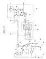
- Prior art date
- Legal status (The legal status is an assumption and is not a legal conclusion. Google has not performed a legal analysis and makes no representation as to the accuracy of the status listed.)
- Expired - Lifetime
Links
Images





Classifications
-
- B—PERFORMING OPERATIONS; TRANSPORTING
- B01—PHYSICAL OR CHEMICAL PROCESSES OR APPARATUS IN GENERAL
- B01D—SEPARATION
- B01D59/00—Separation of different isotopes of the same chemical element
- B01D59/02—Separation by phase transition
- B01D59/04—Separation by phase transition by distillation
-
- F—MECHANICAL ENGINEERING; LIGHTING; HEATING; WEAPONS; BLASTING
- F25—REFRIGERATION OR COOLING; COMBINED HEATING AND REFRIGERATION SYSTEMS; HEAT PUMP SYSTEMS; MANUFACTURE OR STORAGE OF ICE; LIQUEFACTION SOLIDIFICATION OF GASES
- F25J—LIQUEFACTION, SOLIDIFICATION OR SEPARATION OF GASES OR GASEOUS OR LIQUEFIED GASEOUS MIXTURES BY PRESSURE AND COLD TREATMENT OR BY BRINGING THEM INTO THE SUPERCRITICAL STATE
- F25J3/00—Processes or apparatus for separating the constituents of gaseous or liquefied gaseous mixtures involving the use of liquefaction or solidification
- F25J3/08—Separating gaseous impurities from gases or gaseous mixtures or from liquefied gases or liquefied gaseous mixtures
-
- F—MECHANICAL ENGINEERING; LIGHTING; HEATING; WEAPONS; BLASTING
- F25—REFRIGERATION OR COOLING; COMBINED HEATING AND REFRIGERATION SYSTEMS; HEAT PUMP SYSTEMS; MANUFACTURE OR STORAGE OF ICE; LIQUEFACTION SOLIDIFICATION OF GASES
- F25J—LIQUEFACTION, SOLIDIFICATION OR SEPARATION OF GASES OR GASEOUS OR LIQUEFIED GASEOUS MIXTURES BY PRESSURE AND COLD TREATMENT OR BY BRINGING THEM INTO THE SUPERCRITICAL STATE
- F25J2205/00—Processes or apparatus using other separation and/or other processing means
- F25J2205/82—Processes or apparatus using other separation and/or other processing means using a reactor with combustion or catalytic reaction
-
- F—MECHANICAL ENGINEERING; LIGHTING; HEATING; WEAPONS; BLASTING
- F25—REFRIGERATION OR COOLING; COMBINED HEATING AND REFRIGERATION SYSTEMS; HEAT PUMP SYSTEMS; MANUFACTURE OR STORAGE OF ICE; LIQUEFACTION SOLIDIFICATION OF GASES
- F25J—LIQUEFACTION, SOLIDIFICATION OR SEPARATION OF GASES OR GASEOUS OR LIQUEFIED GASEOUS MIXTURES BY PRESSURE AND COLD TREATMENT OR BY BRINGING THEM INTO THE SUPERCRITICAL STATE
- F25J2205/00—Processes or apparatus using other separation and/or other processing means
- F25J2205/86—Processes or apparatus using other separation and/or other processing means using electrical phenomena, e.g. Corona discharge, electrolysis or magnetic field
-
- F—MECHANICAL ENGINEERING; LIGHTING; HEATING; WEAPONS; BLASTING
- F25—REFRIGERATION OR COOLING; COMBINED HEATING AND REFRIGERATION SYSTEMS; HEAT PUMP SYSTEMS; MANUFACTURE OR STORAGE OF ICE; LIQUEFACTION SOLIDIFICATION OF GASES
- F25J—LIQUEFACTION, SOLIDIFICATION OR SEPARATION OF GASES OR GASEOUS OR LIQUEFIED GASEOUS MIXTURES BY PRESSURE AND COLD TREATMENT OR BY BRINGING THEM INTO THE SUPERCRITICAL STATE
- F25J2210/00—Processes characterised by the type or other details of the feed stream
- F25J2210/50—Oxygen
-
- F—MECHANICAL ENGINEERING; LIGHTING; HEATING; WEAPONS; BLASTING
- F25—REFRIGERATION OR COOLING; COMBINED HEATING AND REFRIGERATION SYSTEMS; HEAT PUMP SYSTEMS; MANUFACTURE OR STORAGE OF ICE; LIQUEFACTION SOLIDIFICATION OF GASES
- F25J—LIQUEFACTION, SOLIDIFICATION OR SEPARATION OF GASES OR GASEOUS OR LIQUEFIED GASEOUS MIXTURES BY PRESSURE AND COLD TREATMENT OR BY BRINGING THEM INTO THE SUPERCRITICAL STATE
- F25J2215/00—Processes characterised by the type or other details of the product stream
- F25J2215/50—Oxygen or special cases, e.g. isotope-mixtures or low purity O2
-
- F—MECHANICAL ENGINEERING; LIGHTING; HEATING; WEAPONS; BLASTING
- F25—REFRIGERATION OR COOLING; COMBINED HEATING AND REFRIGERATION SYSTEMS; HEAT PUMP SYSTEMS; MANUFACTURE OR STORAGE OF ICE; LIQUEFACTION SOLIDIFICATION OF GASES
- F25J—LIQUEFACTION, SOLIDIFICATION OR SEPARATION OF GASES OR GASEOUS OR LIQUEFIED GASEOUS MIXTURES BY PRESSURE AND COLD TREATMENT OR BY BRINGING THEM INTO THE SUPERCRITICAL STATE
- F25J2220/00—Processes or apparatus involving steps for the removal of impurities
- F25J2220/90—Separating isotopes of a component, e.g. H2, O2
-
- Y—GENERAL TAGGING OF NEW TECHNOLOGICAL DEVELOPMENTS; GENERAL TAGGING OF CROSS-SECTIONAL TECHNOLOGIES SPANNING OVER SEVERAL SECTIONS OF THE IPC; TECHNICAL SUBJECTS COVERED BY FORMER USPC CROSS-REFERENCE ART COLLECTIONS [XRACs] AND DIGESTS
- Y02—TECHNOLOGIES OR APPLICATIONS FOR MITIGATION OR ADAPTATION AGAINST CLIMATE CHANGE
- Y02E—REDUCTION OF GREENHOUSE GAS [GHG] EMISSIONS, RELATED TO ENERGY GENERATION, TRANSMISSION OR DISTRIBUTION
- Y02E60/00—Enabling technologies; Technologies with a potential or indirect contribution to GHG emissions mitigation
- Y02E60/30—Hydrogen technology
- Y02E60/36—Hydrogen production from non-carbon containing sources, e.g. by water electrolysis
-
- Y—GENERAL TAGGING OF NEW TECHNOLOGICAL DEVELOPMENTS; GENERAL TAGGING OF CROSS-SECTIONAL TECHNOLOGIES SPANNING OVER SEVERAL SECTIONS OF THE IPC; TECHNICAL SUBJECTS COVERED BY FORMER USPC CROSS-REFERENCE ART COLLECTIONS [XRACs] AND DIGESTS
- Y10—TECHNICAL SUBJECTS COVERED BY FORMER USPC
- Y10S—TECHNICAL SUBJECTS COVERED BY FORMER USPC CROSS-REFERENCE ART COLLECTIONS [XRACs] AND DIGESTS
- Y10S203/00—Distillation: processes, separatory
- Y10S203/08—Waste heat
-
- Y—GENERAL TAGGING OF NEW TECHNOLOGICAL DEVELOPMENTS; GENERAL TAGGING OF CROSS-SECTIONAL TECHNOLOGIES SPANNING OVER SEVERAL SECTIONS OF THE IPC; TECHNICAL SUBJECTS COVERED BY FORMER USPC CROSS-REFERENCE ART COLLECTIONS [XRACs] AND DIGESTS
- Y10—TECHNICAL SUBJECTS COVERED BY FORMER USPC
- Y10S—TECHNICAL SUBJECTS COVERED BY FORMER USPC CROSS-REFERENCE ART COLLECTIONS [XRACs] AND DIGESTS
- Y10S203/00—Distillation: processes, separatory
- Y10S203/09—Plural feed
-
- Y—GENERAL TAGGING OF NEW TECHNOLOGICAL DEVELOPMENTS; GENERAL TAGGING OF CROSS-SECTIONAL TECHNOLOGIES SPANNING OVER SEVERAL SECTIONS OF THE IPC; TECHNICAL SUBJECTS COVERED BY FORMER USPC CROSS-REFERENCE ART COLLECTIONS [XRACs] AND DIGESTS
- Y10—TECHNICAL SUBJECTS COVERED BY FORMER USPC
- Y10S—TECHNICAL SUBJECTS COVERED BY FORMER USPC CROSS-REFERENCE ART COLLECTIONS [XRACs] AND DIGESTS
- Y10S203/00—Distillation: processes, separatory
- Y10S203/90—Particular type of heating
Definitions
- the present invention relates to an apparatus for separation/enrichment of isotopes of a uniform compound, and to an apparatus and method for obtaining heavy oxygen water in which the oxygen isotopes 17 O and 18 O (referred to as heavy oxygen isotopes) within the water molecules have been enriched.
- the present invention relates to a method of producing water enriched in the oxygen isotopes of 17 O and 18 O in which oxygen is enriched in 16 O 17 O, 16 O 18 O, 17 O 17 O, 17 O 18 O, and 18 O 18 O by cryogenic distillation of oxygen, and then converted to water, and to a method of producing water which is further enriched in the oxygen isotopes of 17 O and 18 O in which oxygen is enriched in 16 O 17 O , 16 O 18 O, 17 O 17 O , 17 O 18 O and 18 O 18 O by cryogenic distillation of oxygen, and then converted to water which is then subj ect to water distillation.
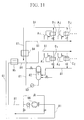
- Figure 18 shows an example of an apparatus provided with three distillation columns with each of the columns (first to third columns 61, 62, and 63) connected.
- the liquid which accumulates in the bottom of the first distillation column 61 and the second distillation column 62 is supplied by means of pumps 61 a and 62a to the tops of second distillation column 62 and third distillation column 63 respectively as reflux liquid. Vapor which is drawn off from the top of the second column 62 and the third column 63 is returned to the bottoms of the first column 61 and the second column 62 respectively as ascending vapor.
- the supply of the process fluid from the first column 61 to the second column 62 and from the second column 62 to the third column 63 is carried out by liquid pumps 61 a and 62a, but the return of the process liquid from the second column 62 to the first column 61, and from the third column 63 to the second column 62 occurs due to the pressure differences in the vapor. Therefore, the pressure within the distillation columns must be successively higher from the first column 61 toward the third column 63. In general, since the relative vapor pressure (separation factor) is smaller the higher the operating pressure of the distillation column, distillation efficiency is lower in the second column 62 than the first column 61, and lower in the third column 63 than in the second column 62.
- the start-up time the time (hereinafter referred to as the start-up time) from the start up of the apparatus until it becomes possible to collect the stipulated amount (the product amount extracted in accordance with the specifications, or the planned value) may take from several month 5 to several years. Consequently, reduction of the start-up time has hitherto been an issue.
- the start-up time is heavily dependent on the process liquid hold-up within the apparatus, and the greater the amount thereof, the longer the start-up time is.
- Figure 19 shows a distillation process havinglalthe same functions as the apparatus shown in Figure 18, and each column 71, 72, and 73 are provided with condensers 5, 7 and 9, and reboilers 6, 8, and 10. These are apparatuses which are generally used in processes comprising a plurality of distillation columns. The diameter of the distillation columns becomes smaller from the column 71 to which the starting material is fed to the column 73 which is downstream from column 71.
- the present invention has as an object the provision of an apparatus comprising a plurality of distillation columns and with which the start-up time is shorter than with conventional apparatuses.
- liquid hold-up volume is reduced, and this makes it possible for the start-up time of the device to be reduced even further.
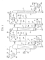
- Figure 1 shows a first embodiment of the apparatus of the present invention.
- the apparatus shown here is equipped with three distillation columns, a first column 1, a second column 2, and a third column 3, constructed in a cascade.
- constructed in a cascade means that the distillation columns are connected in such a way that the enriched product of one column can be further enriched in the next distillation column, and then can be further enriched again in the next distillation column, and all the distillation columns together constructed in this way are referred to a cascade process.
- path indicated by the broken line is a modification of the present embodiment, and is not included in the apparatus of the present embodiment.
- a first condenser 5, a second condenser 7, and a third condenser 9 which cool and liquefy at least a part of the vapor drawn off from the tops of the first column 1, the second column 2, and the third column 3 respectively are provided in the vicinity of the tops of these first to third columns 1, 2, and 3.
- Condensers 5, 7 and 9 have first conduits 5a, 7a, and 9a, respectively, into which vapor drawn off from the tops of column 1,2, and 3, respectively, is introduced, and second conduits 5 b, 7b, and 9b through which a medium for heat exchange flows, and are arranged in such a way that the above-mentioned drawn-off vapor can be cooled and liquefied by means of heat exchange with the medium for heat exchange.
- condensers 5, 7, and 9 it is preferable to use a plate fin type condenser.
- condensers 5, 7, and 9 are provided outside of the columns 1, 2, and 3, however, they may also be provided within the tops of the columns 1, 2, and 3.
- a first reboiler 6, a second reboiler 8, and a third reboiler 10 which heat and vaporize at least a part of the liquid drawn off from the bottom of the columns 1, 2, and 3, respectively, are provided in the vicinity of the bottoms of the columns 1, 2, and 3.
- Reboilers 6, 8, and 10 have first conduits 6a, 8a, and 10a, respectively, into which liquid drawn off from the columns 1, 2, and 3 is introduced, and second conduits 6b, 8b, and 10b through which a medium for heat exchange flows, and are arranged in such a way that the above-mentioned drawn-off liquid can be heated and vaporized by means of heat exchange with the medium for heat exchange.
- reboilers 6, 8, and 10 it is preferable to use a plate fin type reboilers.
- the position of installation of these reboilers is such that the amount of liquid which accumulates at the bottom of each column is reduced to a minimum range within which operation is possible in order to reduce the liquid hold up.
- the reboilers 6, 8, and 10 are provided outside of columns 1, 2, and 3, however, they may also be provided within the bottoms of columns 1, 2, and 3. In that situation, a coil type reboiler is also suitable.
- the outlet (the outlet of first conduit 6a) of reboiler 6 of the first column which is provided in the vicinity of the bottom of the first column 1, and the inlet of the condenser 7 of the second column which is provided in the vicinity of the top of the second column are connected by a first introduction conduit 12 via a valve 12v.
- the outlet (the outlet of first conduit 7a) of the condenser 7 of the second column and the inlet (the inlet of the first conduit 6a) of the reboiler 6 of the second column are connected by means of the first return conduit 14 via valve 14v.
- outlet (the outlet of first conduit 9a) of the condenser 9 of the third column and the inlet (the inlet of the first conduit 8a) of the reboiler 8 of the second column are connected by means of the second return conduit 15 via valve 15v.
- valve 14v and valve 15v are in the upper part (close to the condenser) of return conduits 14 and 15, at a position where it is possible to obtain a head pressure with which the pressure difference between the k 1h columns and the (k+1) th columns in a cascade series of a plurality of columns mentioned below is a pressure difference between each column such that this cascade system functions.
- the insides of the first to third columns 1, 2, and 3 are packed with structured packing 11.
- non-promoting-fluid-dispersion type structured packing and/or promoting-fluid-dispersion type structured packing can be suitably used.
- Non-promoting-fluid-dispersion type structured packing has a shape and structure with which the liquid descending within the distillation column and the vapor ascending within the distillation column flow in opposition to one another along the surface of the packing, and vapor-liquid contact occurs without the promotion of mixing of the liquid and vapor in the horizontal cross-section direction with respect to the column axis.
- a packing material in which a large number of plates formed from aluminum, copper, alloy of aluminum and copper, stainless steel, various types of plastic, or the like are positioned parallel to the direction of the main flow (the direction of the column axis) can be mentioned.
- the main flow indicates the descending liquid and the ascending vapor which occurs along the direction of the column axis within the distillation column, therefore, it indicates the flow in the direction of the column axis with respect to the flow of mass transfer which is produced at the liquid-vapor interface (in other words, the boundary layer) at the surface of the packing.
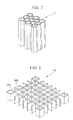
- the non-promoting-fluid-dispersion type structured packing 51 shown in Figure 2 has a honeycomb structure comprising plates parallel to the direction of the axis of the column.
- non-promoting-fluid-dispersion type structured packing 52 shown in Figure 3 is a lattice structure comprising a plurality of mutually parallel plates 52a and a plurality of plates 52b which are arranged at right angles with respect to the plates 52a, and this lattice structure is positioned along the direction of the column axis.
- Promoting-fluid-dispersion type structured packing has a shape and structure with which vapor-liquid contact occurs mainly on the surface of the above-mentioned structured packing between the liquid descending within the distillation column and the vapor ascending within the distillation column, at which time, the liquid and the vapor flow in opposition to one another on the surface of the above-mentioned structured packing in the direction of the main flow which is along the direction of the column axis, and at the same time, mixing of the liquid and/or the vapor in a direction at right angles to the above-mentioned main flow direction is promoted and vapor-liquid contact occurs.
- structured packing or regular packing in which thin plates of aluminum, copper, aluminum-copper alloy, stainless steel, various plastics, or the like are formed into a variety of regular forms, and then made into a laminated block.
- a plurality of wave-shaped thin plates are disposed parallel to the column axis and made into the form of a block by layering the plates so that they come into contact with one another.
- the wave-shaped grooves in each of the thin plates are inclined with respect to the column axis, and neighboring wave-shaped thin plates are disposed so that the direction of their wave-shaped grooves intersect one another.
- a plurality of holes 53a are provided in the thin plates. When the thin plates are disposed perpendicular with respect to the horizontal plane, the holes are provided with an interval of spacing there between and form a plurality of rows along a direction which is at right angles to the column axis.
- Figure 5 shows an example of a structural unit of another promoting-fluid-dispersion type structured packing.
- a thin plate is molded pressed in a wave shape to form wave-shaped grooves.
- this example has the feature that extremely small wave-shaped grooves 54b are formed in the thin plates at a fixed angle with respect to the wave-shaped grooves.
- reference 54a indicates holes formed in the thin plate.
- the promoting-fluid-dispersion type structured packing 55 shown in Figure 6 has the feature of having a structure in which sections having extremely small grooves 55b formed at a fixed angle with respect to the wave-shaped grooves and smooth sections which do not have these extremely small grooves are provided alternately in the wave-shaped thin plate.
- the reference 55a indicates holes formed in the thin plates.
- an oxygen starting material is supplied to the inside of the first column 1 as first column feed 101 via a conduit 20 which serves as a feeding section connected to the first distillation column 1 at a position intermediate (intermediate position in the height direction).
- oxygen with high purity is preferred as the above-mentioned oxygen vapor starting material.
- oxygen of high purity it is possible to use oxygen with a purity of 99.999% or higher, from which impurities such as argon, hydrocarbons, krypton, xenon, and fluorine compounds (such as perfluorocarbons) have been removed in advance.
- impurities such as argon, hydrocarbons, krypton, xenon, and fluorine compounds (such as perfluorocarbons) have been removed in advance.
- the use of an oxygen starting material from which hydrocarbons have been removed is preferable from the point of view of safety.
- the oxygen starting material vapor supplied to the first column 1 is distilled by means of vapor-liquid contact with a reflux liquid (i.e., descending liquid) described below, when ascending within the first column 1 and passing through the packing 11.
- a reflux liquid i.e., descending liquid
- the oxygen molecules in the oxygen starting material vapor which contain heavy oxygen isotopes are more likely to condense due to their high boiling points, and in the process of vapor-liquid contact, the concentration of heavy oxygen isotopes in the descending liquid increases, and the concentration of heavy oxygen isotopes in the ascending vapor decreases.
- the ascending vapor which reaches the top of the column and which has a reduced concentration of heavy isotopes is drawn off from the column 1 via conduit 21, and is divided into two parts.
- One part is introduced into the first conduit 5a of the first column condenser 5 where it is exchanges heat with the medium for heat exchange flowing within the second conduit 5b, condenses, and is returned to the top of column 1 as reflux liquid.
- the other part is discharged out of the system as exhaust vapor 103 through the conduit 22.
- the reflux liquid returned to the top of the first column 1 flows down as descending liquid over the structure packing 11 while making vapor-liquid contact with the oxygen starting material vapor and the below-mentioned ascending vapor which are ascending within the column 1, and reaches the bottom of the column 1.
- the descending liquid becomes enriched in heavy oxygen isotopes (i.e. 16 O 17 O, 16 O 18 O, 17 O 17 O, 17 O 18 O, and 18 O 18 O), which have a greater tendency to liquefy.
- heavy oxygen isotopes i.e. 16 O 17 O, 16 O 18 O, 17 O 17 O, 17 O 18 O, and 18 O 18 O
- Liquid which reaches the bottom of the first column 1 (hereinafter, the liquid which accumulates at the bottom of each of the columns is referred to as the "column bottom liquid”) is drawn off from the column 1 through conduit 23, and is combined with the below-mentioned first return liquid 107 in the above-mentioned first return conduit 14, and then introduced into the first conduit 6a of the first column reboiler 6, where it is vaporized by heat exchange with the medium for heat exchange flowing within the second conduit 6b, and then drawn off from the reboiler 6 via the above-mentioned first introduction conduit 12 as first column output vapor 102 which is an enriched material enriched in heavy oxygen isotopes.
- a part of the first column output vapor 102 drawn off from reboiler 6 is returned to the lower part of the first column 1 via conduit 24, and rises within the column 1 as ascending vapor.
- the other part passes along first introduction conduit 12 as second column feed vapor 104, is combined with the below-mentioned second column top vapor 106, and introduced into the second column condenser 7.
- it condenses, drawn off from the condenser 7 via the return conduit 14 and then divided into two parts.
- a part of the condensed liquid which has passed through the second column condenser 7 is returned to the first column reboiler 6 as first return liquid 107, and the return liquid under its own weight (head pressure) is introduced into the first column 1 by passing through the reboiler 6, therefore, the pressure within the top of the second column 2 can be made to be lower than the pressure of the bottom of the first column 1.
- the other part of the condensed liquid which was divided after being drawn off from the condenser 7 is supplied to the top of the second column 2 as second column reflux liqui through conduit 25, and flows down as descending liquid while making vapor-liquid contact with the ascending vapor within the second column 2 to reach the bottom of the second column 2.
- the ascending vapor which reaches the top of the column and which has a reduced concentration of heavy isotopes is drawn off from column 2 via the conduit 28, and is combined as top vapor 106 with the second column feed vapor 104 in the above-mentioned introduction conduit 12.
- the column bottom liquid of the second column 2 which is an enriched material enriched in heavy oxygen isotopes is drawn off from the second column via conduit 26, is combined with the below-mentioned second return liquid 112 in the above-mentioned second return conduit 15, and introduced into the second column reboiler 8.
- second column output vapor 105 which is enriched material enriched in heavy oxygen isotopes.
- a part of the second column output vapor 105 drawn off from reboiler 8 is returned to the lower part of the column 2 via the conduit 27, and becomes ascending vapor which ascends within the second column 2.
- the other part passes along introduction conduit 13 as third column feed vapor 108, is combined with the below-mentioned third column top vapor 111, and is introduced into the third column condenser 9.
- it condenses, is drawn off from the condenser 9 through second return conduit 15, and is then divided into two parts.
- a part of the condensed liquid which has passed through the third column condenser 9 is returned to the second column reboiler 8 as second return liquid 112, and this return liquid under its own weight (head pressure) is introduced into the second column 2 by passing through the reboiler 8, therefore, the pressure within the top of the third column 3 can be made to be lower than the pressure of the bottom of the second column 2.
- the other part of the condensed liquid which was divided after being drawn off from the condenser 9 is supplied to the top of the third column 3 as third column reflux liquid through conduit 29, and flows down as descending liquid while making vapor-liquid contact with the ascending vapor within the third column 3 to reach the bottom of the third column 3.
- the column bottom liquid of the third column 3 which is an enriched material enriched in heavy oxygen isotopes is drawn off from the column 3 via conduit 30, and introduced into the third column reboiler 10.
- third column output vapor 109 which is enriched material enriched in heavy oxygen isotopes.
- This third column output vapor 109 from the reboiler 10 is divided into two parts. One part is returned to the lower part of the column 3 via the conduit 31. and becomes ascending vapor which ascends within the third column 3. The other part passes along conduit 32 and is collected as product vapor 110 which is an enriched product enriched in heavy oxygen isotopes.
- the flow rate of the second column feed vapor 104 is set to obtain a sufficient amount for the flow rate of the desired component accompanying the second column feed vapor 104 with respect to the flow rate of the desired component accompanying the product (for this embodiment, this is only the product vapor 110) collected to the outside of the apparatus from the second column or the third column.
- the setting is preferable for the setting to be such that the yield of this desired component to be 1% to 10% or less.
- the distillation efficiency of the second column and the third column are reduced.
- the distillation efficiency does not improve very much with respect to the increase in the amount of heat exchange in the first column reboiler 6 and the second column condenser 7.
- the flow rate of the third column feed vapor 108 is set to obtain a sufficient amount for the flow rate of the desired component accompanying the third column feed vapor 108 with respect to the flow rate of the desired component accompanying the product (for this embodiment, this is only the product vapor 110) recovered to the outside of the apparatus from the third column.
- the distillation efficiency of the third column is reduced.
- the distillation efficiency does not improve very much with respect to the increase in the amount of heat exchange in the second column reboiler 8 and the third column condenser 9.
- the adjustment of 3 the amount of heat exchange in the reboiler (the pressure and flow rate of the warm medium), is carried out in the following way.
- the setting it is maintaining the amount of heat exchange in the reboiler after it has been set in advance so that the vapor load of each column is at a suitable value (planned value). It is preferable for the setting to be such that the density correlated superficial velocity (hereinafter referred to as the superficial F factor) is 0.5 m/s(kg/m 3 ) 0.5 or greater and 3.0 m/s(kg/m 3 ) 0.5 or less, preferably 0.7 m/s(kg/m 3 ) 0.5 or greater and 2.2 m/s(kg/m 3 ) 0.5 or less.
- the superficial F factor density correlated superficial velocity
- valves 12v and 13v which are in the piping (conduits 12 and 13) which supply vapor from the k th column to the (k+1) th column are adjusted.
- the pressure at the tops of each of the columns is approximately equal, the pressure at the bottom of the k th column is greater than the pressure at the top of the (k+1) th column by amount of the pressure loss in the k th column. Consequently, in addition to the provision of a valve in way along of the piping, the flow rate of the vapor supplied from the k th column to the (k+1) th column is measured, and controlled to predetermined flow rate. This flow rate is not a strict one and once a precise and suitable flow rate is established, the degree of opening of the valve is not adjusted.
- the pressure of each column is constant, this flow rate rarely fluctuates.
- the amount of heat exchange in the condenser (the pressure and flow rate of the cold medium) is set. This is set such that the pressure within each of the distillation columns are constant. Since (3) the amount of heat exchange in the reboilers is fixed, if the (4) amount of heat exchange in the condenser is small, the pressure in the distillation columns continues to increase.
- control values 14v and 15v are installed at a position relatively close to the condenser at the top of the column within a range at which it is possible to obtain a prescribed liquid head. This is in order to reduce the liquid hold-up within the piping.
- the degree of opening of these valves is adjusted while measuring the liquid level at the bottom of each columns.
- valve of the liquid piping must be controlled in such a way that the height of the level of the liquid in the bottom of each distillation column is constant.
- valves 14v and 15v are installed at a position relatively close to the condensers of the tops of the columns within a range at which it is possible to obtain a prescribed liquid head.
- the valves 14v and 15v are installed at a position relatively close to the condensers of the tops of the columns within a range at which it is possible to obtain a prescribed liquid head.
- the outlet of the second column condenser 7 and the inlet of the first column reboiler 6 are connected by the first return conduit 14 and the outlet of the third column condenser 9 and the inlet of the second column reboiler 8 are connected by the return conduit 15.
- the apparatus of the present invention is not limited to this, the first conduit can be used to connect the outlet of the second condenser 7 and the middle section of the first column 1 as shown by reference 14a (the conduit indicated by the broken line), and the second return conduit can be used to connect the outlet of the third column condenser 9 and the middle section of the second column 2 as shown by reference 15a (the conduit indicated by the broken line).
- columns 1, 2 and 3 are not limited to packed columns in which the above-mentioned packing is used, and it is also possible to use wetted wall columns.
- FIG 7 shows a second embodiment of the apparatus of the present invention.
- the apparatus shown here is different to the apparatus shown in Figure 1 on the following points.
- the conduit indicated by the broken line in the figure is a modification of the apparatus of the present embodiment.
- An oxygen vapor starting material supplied to the inside of the first column 1 as first column feed 101 via a conduit 20 is distilled by means of vapor-liquid contact within the first column 1.
- the column bottom liquid which has been enriched in heavy oxygen isotopes within the first distillation column 1 is introduced into the first column reboiler 6 through the conduit 23', is vaporized, and is drawn off from the first column reboiler 6 as the first column output vapor 102'.
- a part of the output vapor 102' is returned to the lower part of the first column 1 via conduit 39, and the other part is introduced directly into the top of the second column 2 through first introduction conduit 35 as second column feed vapor 104'.
- the ascending vapor which reaches the top of the column and which has a reduced concentration of heavy oxygen isotopes is drawn off from the second column 2 through the conduit 28' as column top vapor 106. It is condensed in the second column condenser 7, and then divided. One part is returned as reflux liquid to the upper part of the second column 2 through the conduit 25'. The other part is returned to the bottom of the first column 1 as first return liquid 107' through the first return conduit 37.
- the column bottom liquid which has been enriched in heavy oxygen isotopes within the second column 2 is introduced into the second column reboiler 8 through conduit 26', where it is vaporized, and then drawn off from the reboiler 8 as second column output vapor 105'.
- a part of the output vapor 105' is returned to the lower part of the second column 2 through conduit 40.
- the other part is directly introduced into the top of the third column 3 through the second introduction conduit 36 as the third column feed 108'.
- the ascending vapor which reaches the top of the column and which has a reduced concentration of heavy oxygen isotopes is drawn off from the third column 3 through the conduit 33' as column top vapor 111. It is condensed in the third column condenser 9, and then divided. One part is introduced as reflux liquid to the upper part of the third column 3 through the conduit 29'. The other part is returned to the bottom of the second column 2 as second return liquid 112' through the second return conduit 38.
- the apparatus of the present embodiment it is possible to return a part of the condensed liquid which has passed through the condensers 7 and 9 to the previous stage column by means of the weight (head pressure) of the condensed liquid itself. For this reason, the amount of liquid can be less compared with conventional methods which use liquid pumps, and, as with the apparatus of the above-described first embodiment, it is possible to shorten the start-up time. In addition, as a result of a shorter total column length due to the adoption of a form in which the bottoms of the columns and the tops of the columns are connected, it is possible to obtain a product containing a high concentration of heavy oxygen isotopes with good efficiency.
- the outlet of the first column reboiler 6 and the top of the second column 2 are connected by means of the first introduction conduit 35, and the outlet of the second column reboiler 8 and the top of the third column 3 are connected by means of the second introduction conduit 36, in addition, the outlet of the second column condenser 7 and the bottom of the first column 1 are connected by means of the return conduit 37, and the outlet of the third column condenser 9 and the bottom of the second column 2 are connected by means of the second return conduit 38.
- the apparatus of the present invention is not limited to this.
- first and second introduction conduits are connected to the middle sections of columns 2 and 3 rather than to the tops of columns 2 and 3 as shown by references 35a and 36a (the conduits indicated by the broken lines).
- first and second return conduits are also possible for the first and second return conduits to be connected to the middle sections of the first and second columns rather than to the bottoms of the first and second columns as shown by references 37a and 38a.
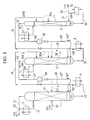
- FIG 8 shows a third apparatus (not according to the present invention).
- the apparatus shown here differs from the apparatus shown in Figure 7 on the following points.
- blowers 41 and 42 normal temperature compressors or low temperature compressors can be used. However, when a normal temperature compressor is used, as shown in Figure 9, it is necessary to have heat exchanges 41a and 42a in the return conduits 37' and 38'.
- top vapor 106 which has been divided is condensed in the second column condenser 7, and is then returned to the top of the second column 2 where it becomes reflux liquid for that column.
- the other part passes through the first return conduit 37' and reaches the blower 41 where it is pressurized, and then returned to the bottom of the first column 1 as first return liquid 107".
- the column top vapor 111 drawn of from the top of the third column 3 is divided after being drawn off from the third column 3.
- One part is condensed in the third column condenser 9, and then return to the top of the third column to become reflux liquid for that column.
- the other part passes along the second return conduit 38' and reaches the blower 42 where it is pressurized and then returned to the bottom of the second column 2 as second return liquid 112".
- the outlet of the first column reboiler 6 and the top of the second column 2 are connected by means of the first introduction conduit 35, and the outlet of the second column reboiler 8 and the top of the third column 3 are connected by means of the second introduction conduit 36, and in addition, the inlet of the second column condenser 7 and the bottom of the first column 1 are connected by means of the first return conduit 37' and the inlet of the third column condenser 9 and the bottom of the second column 2 are connected by means of the second return conduit 38'.
- the present embodiment is not limited to this.
- first and second introduction conduits are connected to the middle sections of the second and third columns 2 and 3 as shown by references 35a and 36a (the conduits indicated by the broken lines), and for the first and second return conduits to be connected to the middle sections of the first and second columns rather than to the bottoms of the first and second columns as shown by the references 37'a and 38'a.
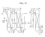
- the number of distillation columns is n.
- the apparatus shown here comprises n number of distillation columns A 1 to An; condensers B 1 to B n which are provided in the vicinity of the top of these distillation columns A 1 to An; reboilers C 1 to C n which are provided in the vicinity of the bottoms of the columns A 1 to A n ; introduction conduits D 1 to D n-1 which connect the outlets of the k th column reboilers C k provided in the vicinity of the bottoms of the k th columns (1 ⁇ k ⁇ (n-1)) to the tops of the (k+1) th columns; and return conduits E 1 to E n-1 which connect the outlets of the (k+1) th column condensers B k+1 of the (k+1 1) th columns to the bottoms of the k th columns.
- the number n of the distillation columns can be, for example, from 2 to 100.
- each of the condensers B 1 to B n , and reboilers C 1 to C n are connected by means of the circulation conduit 81 for the medium for heat exchange.
- This circulation conduit 81 is such that the medium for heat exchange within the storage tank 82 is drawn off, passes through the pump 83 and the first passage of the subcooler 84, and is introduced into the condensers B 1 to B n . Then, it passes through the second passage of the subcooler 84 and reaches the first conduit of the heat exchanger 85. Next, it passes through the blower 86 and the second passage of the heat exchanger 85, is introduced into the reboilers C 1 to C n , and then returned to the storage tank 82.
- the subcooler 84 is for the purpose of cooling the medium for heat exchange in order to prevent vaporization of the medium for heat exchange prior to it reaching the condensers.
- the number of distillation columns is not limited to the number shown in the figures for the apparatus of the first embodiment shown in Figure 1, the apparatus of second embodiment shown in Figure 7, and the apparatus of the third embodiment shown in Figure 8, and can be set optionally.
- the above-described embodiment shows a method for enrichment in the heavy isotopes of oxygen by means of cryogenic distillation of an oxygen starting material.
- the present invention is not limited to this. It is also possible to produce heavy oxygen water by carrying out distillation using water as the starting material and using the apparatus of the above-described embodiments to distill this water to enrich it in at least one type of heavy oxygen water of H 2 17 O , H 2 18 O , D 2 17 O, D 2 18 O, DH 17 O and DH 18 O which contain heavy oxygen isotopes.
- FIG. 12 and Figure 13 show an apparatus which can be used for carrying out another method of producing heavy oxygen water (not according to the present invention)
- the apparatus shown here comprises an oxygen distillation column unit F 1 for distillation of oxygen which comprises a plurality of distillation columns A 1 to An; a water distillation column unit F 2 for distillation of water which comprises a plurality of distillation columns A' 1 to A' n ; and a hydrogenation reaction device 300A provided between these units F 1 and F 2 .
- the distillation column units F 1 and F 2 may adopt the structure of the apparatus shown in Figure 10.
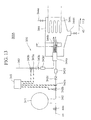
- the hydrogenation reaction device 300A shown in Figure 13 comprises a buffer tank 341 for temporarily storing the enriched material (oxygen) which has passed through the oxygen distillation column unit F 1 ; a conduit 44 for introducing the oxygen into the buffer tank 341; a conduit 343 for introducing hydrogen (or deuterium) supplied from a supply source not shown in the figure; a combustion chamber 344 for reacting the oxygen and hydrogen supplied from the conduits 342 and 343; and a combustor 300 having a controller 345.
- a buffer tank 341 for temporarily storing the enriched material (oxygen) which has passed through the oxygen distillation column unit F 1 ; a conduit 44 for introducing the oxygen into the buffer tank 341; a conduit 343 for introducing hydrogen (or deuterium) supplied from a supply source not shown in the figure; a combustion chamber 344 for reacting the oxygen and hydrogen supplied from the conduits 342 and 343; and a combustor 300 having a controller 345.
- the combustion chamber 344 comprises a burner 344a for mixing and combusting oxygen and hydrogen supplied into the combustion chamber 344; a heater 344b for igniting the oxygen-hydrogen mixed gas; and a cooling coil 344c for cooling the reactant product (i.e., water vapor). Additionally, reference 344d indicates a discharge opening which is provided for expelling the reactant product (water) of the combustion chamber 344 via a valve.
- the controller 345 regulates a flow control valve 342b by means of signals based on the flow rate of oxygen measured by an oxygen flow rate detector 342a provided in conduit 342, and thereby the controller 345 is able to adjust the supply flow rate of oxygen supplied into the combustion chamber 344 via the conduit 342.
- controller 345 regulates a flow control valve 343b by means of signals based on the flow rate of hydrogen which is measured by a hydrogen flow rate detector 343a provided in the conduit 343, and thereby the controller 345 is able to adjust the supply volume of hydrogen supplied into the combustion chamber 344 via the conduit 343.
- references 342c and 343c indicate check valves; references 342d and 343d indicate back-fire prevention chambers; and reference 344e indicates a conduit for discharging the small amount of unreacted gas remaining in the combustion chamber 344, via a valve.
- the oxygen starting material is supplied to the oxygen distillation column unit F 1 , and an intermediate vapor 110' is obtained which is an enriched material enriched in the heavy isotopes of oxygen.
- This intermediate vapor 110' (oxygen vapor) is introduced into the combustor 300 of the hydrogenation reaction device 300A via conduit 44 and control valve 44a.
- the oxygen introduced into the combustor 300 passes through the buffer tank 341, and is introduced into the combustion chamber 344 via the conduit 342 and through the burner 344a.
- the hydrogen supplied from a supply source not shown in the figures is supplied to the combustion chamber 344 via the conduit 343 and through the burner 344a.
- the controller 345 performs a calculation based on signal based on a predetermined value and a feedback signal based on the flow rate of oxygen measured by the oxygen flow rate detector 342a.
- the controller regulates the flow rate control valve 342b by means of a signal resulting from this calculation.
- controller 345 performs a calculation based on the signal based on a predetermined value and a feedback signal based on the flow rate of hydrogen measured by the hydrogen flow rate detector 343a.
- the controller regulates the flow rate control valve 343b by means of a signal resulting from this calculation.
- the oxygen and hydrogen supplied to the combustion chamber 344 are always regulated to a volume which closely approximates the aforementioned stoichiometric volume by means of the aforementioned feedback control. However, despite this, excess supplied gas is regularly discharged via a valve from a discharge conduit 344e, and this prevents the gas from accumulating in the combustion chamber 344.
- the aforementioned oxygen and hydrogen supplied into the combustion chamber 344 are mixed by means of the burner 344a, and subsequently, jetted into the combustion chamber 344, ignited by means of the heater 344b, and reacted with each other to produce water.
- this produced water 113 is obtained using the intermediate product vapor 110' which is a enriched material in heavy oxygen isotopes it is heavy oxygen water which contains a large amount of heavy oxygen isotopes.
- the water distillation column unit F 2 has the same structure as the oxygen distillation column unit F 1 , therefore, in the same way as the enrichment process for heavy oxygen isotopes which occurs in the unit F 1 , the heavy components within the produced water 113, that is H 2 17 O, H 2 18 O, D 2 17 O, D 2 18 O, DH 17 O and DH 18 O, are enriched within the distillation unit F 2 and collected as the heavy oxygen water product 114.
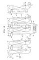
- FIG. 14 shows another apparatus (not according to the present invention)
- the apparatus shown here comprises n number of distillation columns A 1 to A n ; condensers B 1 to B n which are provided in the vicinity of the top of these columns A 1 to A n ; reboilers C 1 to C n which are provided in the vicinity of the bottoms of the columns A 1 to A n ; introduction conduits D 1 to D n-1 which connect the outlets of the k th column reboilers C k provided in the vicinity of the bottoms of the k th columns (1 ⁇ k ⁇ (n-1)) to the tops of the (k+1) th columns; return conduits E 1 to E n-1 which connect the outlets of the (k+1 ) th column condensers B k
- the isotope scrambler 47 is for further enriching the heavy oxygen isotope enriched material enriched by means of the columns A to A h by means of oxygen isotope scrambling.
- the inlet side of the isotope scrambler is connected to the bottom of the h th column A h via the extraction conduit 48, and the outlet side of the isotope scrambler is connected to the middle section of the ith column Al which is at a later stage and adjacent to hth column An via a return conduit 49.
- isotope scrambler 47 in addition to the use of an isotope exchange reaction catalyst, it is possible to temporarily form other compounds from the oxygen molecules, and then subsequently break these compounds down to obtain oxygen molecules.
- the column bottom vapor of column An which is an oxygen isotope enriched material is brought into contact with an isotope exchange reaction catalyst, to promote isotope exchange reactions discussed below within the enriched material, and thereby it is possible to further increase the concentration of molecules of heavy oxygen isotopes within the enriched material.
- the isotope scrambler 47 is provided with a catalytic column (not shown in the figure), and an isotope exchange reaction catalyst which packed inside this catalytic column.
- catalysts containing at least one type selected from the group comprising W, Ta, Pd, Rh, Pt, and Au can be used, for example.
- the isotope exchange reaction catalysts in addition to those mentioned above, it is possible to use a catalyst including at least one type selected from the group comprising Ti-oxide, Zr-oxide, Cr-oxide, Mn-oxide, Fe-oxide, Co-oxide, Ni-oxide, Cu-oxide, Al-oxide, Si-oxide, Sn-oxide, and V-oxide.
- a catalyst including at least one type selected from the group comprising Ti-oxide, Zr-oxide, Cr-oxide, Mn-oxide, Fe-oxide, Co-oxide, Ni-oxide, Cu-oxide, Al-oxide, Si-oxide, Sn-oxide, and V-oxide.
- the column bottom vapor of column Ah which is a heavy oxygen isotope enriched material is temporarily converted to a different compound (for example, water), this is subsequently broken down to give molecular oxygen, and thereby the concentration of molecules of heavy oxygen isotope molecules within the enriched material is further increased.
- a different compound for example, water
- the isotope scrambler 47 comprises an argon circulation blower 87, a catalytic column 88 packed with an oxidation reaction catalyst, an electric catalytic cracker 89, and an oxygen purifier 90.
- a catalyst comprising at least one component selected from among the group comprising Pd, Pt, Rh, Ru, Ni, Cu, and Au can be used.
- Pd, Pt, Rh, Ru, or the like are carried by one of Al-oxide, Si-oxide, Ti oxide, Zr oxide, Cr oxide, V oxide, Co oxide or Mn oxide.
- the argon circulation blower 87 is provided in order to circulate the gas within the argon circulation system having a catalytic column 88, a cooler 91, and a chiller 92. Since oxygen and hydrogen coexist within this circulation system, in consideration of the explosibility range, an argon supply conduit 98 for supplying argon for diluting the vapor within the circulation system is connected to the circulation system.
- this circulation system is provided with a hydrogen supply conduit 97 for the purpose of maintaining the concentration of hydrogen at the outlet of the chiller 92 at approximately 2%.
- Feed 101 is supplied to first column A1 through conduit 20, and, thereafter, it is enriched in heavy oxygen isotopes by following the above-described process until it reaches the column An, and thereby a column bottom liquid of column An which is an enriched material is obtained.
- this column bottom liquid is introduced to the isotope scrambler 47 as introduction oxygen 115 through the conduit 48.
- the oxygen supplied to the suction side of the argon circulation blower 87 from the conduit 48 is mixed with argon and hydrogen, pressurized to approximately 80 to 100 kPa (gauge) by the blower 87, and then introduced into the catalytic column 88.
- small amounts of hydrogen are supplied from the conduit 97.
- the hydrogen and the oxygen are reacted to produce water (2H 2 + O 2 ⁇ 2H 2 O and the composition at the outlet of the catalytic column 88 is approximately 2% hydrogen, approximately 0.5% water vapor, and 97.5% argon.
- This mixture is cooled by means of the cooler 91 and the chiller 92, and the water is separated into the storage tank 93.
- This water is sent to the electrolysis tank 94 (pressure 400 kPa gauge) by means of a pump provided within the electrolysis apparatus 89, undergoes electrolysis, and is separated into hydrogen containing a small amount of oxygen and oxygen vapor containing a small amount of hydrogen again.
- the former hydrogen vapor is recovered from the above-described argon circulation system.
- the small amounts of hydrogen and water in the latter oxygen vapor are removed by means of an oxygen purifier 90 which has a catalytic column 95 and an adsorber 96, and the oxygen is drawn off through conduit 49 and returned to the oxygen distillation column.
- the flow rate of the isotope scrambler return oxygen 116 is extremely low compared with the amount of the ascending vapor within the distillation column to which the oxygen is returned. Therefore, it has almost no influence on the distillation efficiency even if it is returned into the distillation column as it is at normal temperature.
- oxygen and hydrogen are reacted due to the oxidation reaction catalyst and water is produced.
- A, B, C, and D are, respectively, any one of the isotope atoms 16 O, 17 O, and 18 O
- the atoms which make up the oxygen molecules are separated into different molecules of water by means of reactions like the following: 2H 2 + AB ⁇ H 2 A + H 2 B; or 2H 2 + CD ⁇ H 2 C + H 2 D; or 2H 2 + AA ⁇ H 2 A + H 2 A
- the relative abundance of each of the heavy oxygen isotopes within the reaction product (the water molecules) obtained thereby is determined by the relative abundance of each of the isotopes within the introducer oxygen 115.
- the water molecules are broken down into the oxygen molecules and to hydrogen molecules by means of electrolysis.
- A, B, C, and D are, respectively, any one of the isotope atoms 16 O, 17 O, and 18 O
- the water molecules are broken down into oxygen molecules and hydrogen molecules by means of reactions like the following: H 2 A + H 2 C ⁇ 2H 2 + AC; or H 2 B + H 2 D ⁇ 2H 2 + BD; or 2H 2 C ⁇ 2H 2 + CC
- the combination of the oxygen atoms which make up the oxygen molecules obtained here are determined randomly by the relative abundance of the oxygen isotopes present in the water molecules.
- isotope scrambling when a plurality of types of isotope molecules are present as described above, each molecule randomly exchanges the coupled atoms from which it is formed is called “isotope scrambling", and the apparatus in which this takes place is called an “isotope scrambler".
- Isotope exchange is a reaction wherein coupled atoms in a two-atom molecule are exchanged with other atoms on the surface of a sufficiently heated catalyst.
- an isotope atom which couples to form a molecule is randomly determined according to the abundance ratio of each isotope constituent prior to isotope exchange.
- the abundance ratio of each isotope in the reactant material i.e., oxygen isotope molecule
- the abundance ratio of each isotope in the reactant material i.e., oxygen isotope molecule
- the abundance ratio of each isotope in the introducer oxygen 115 is determined according to the abundance ratio of each isotope in the introducer oxygen 115.
- the components of 16 O 16 O, 16 O 17 O, and 16 O 18 O are present in the output vapor 115. If the respective molar ratios of these components is Y 11 , Y 12 , and Y 13 , the combination of oxygen atoms which make up the oxygen molecules changes randomly based on the abundance probability of each of the isotopes by means of the isotope scrambler 47 using either of the above-described methods, the concentration of each component after the isotope scrambling is as follows: O 16 O 16 : ( Y 11 + Y 12 / 2 + Y 13 / 2 ) 2 O 16 O 17 : ( Y 11 + Y 12 / 2 + Y 13 / 2 ) Y 12 O 16 O 18 : ( Y 11 + Y 12 / 2 + Y 13 / 2 ) Y 13 O 17 O 17 : Y 2 12 / 4 O 17 O 18 : Y 12 Y 13 / 2 O 18 O 18 : Y 12 Y 13 /
- a part of the 16 O which is contained in the 16 O 17 O and 16 O 18 O becomes 16 O 16 O, and accompanying this the concentration of oxygen molecules ( 18 O 18 O, 17 O 18 O and 17 O 17 O, hereinafter referred to as heavy oxygen molecules) consisting of the heavy components ( 17 O and 18 O) increases.
- reaction product in which the concentration of heavy oxygen molecules has been increased using the isotope scrambler 47 is supplied to column Al through conduit 49 as isotope scrambler return oxygen 116, and thereafter passes through columns Al to An.
- the heavy oxygen molecules have a higher boiling point and are easily enriched, therefore, the concentration of heavy oxygen isotopes is further increased in this process.
- the heavy oxygen isotope enriched material obtained by means of columns Al to An is supplied to the isotope scrambler 47, the concentration of heavy oxygen molecules within the enriched material is increased by means of isotope scrambling which occurs in the isotope scrambler 47, the enriched material is then supplied to the columns Al to An, and the concentration of heavy oxygen isotopes is further increased. Therefore, it is possible to obtain a product containing a high concentration of heavy oxygen isotopes.
- the apparatus shown in the figure has a structure in which the conduit 49 on the outlet side of the isotope scrambler 47 is connected to the ith column Ai.
- the column to which the conduit 49 on the outlet side of the isotope scrambler 47 is connected is preferably further down stream (to the later stage side) from the hth column An to which the conduit 48 on the inlet side of the isotope scrambler 47 is connected.
- the present invention is not limited to this, and the column to which the outlet side conduit 49 is connected may be the column to which the inlet side conduit 48 is connected or may be upstream (to the earlier stage side) from that column.
- the isotope scrambler 47 can be inserted at any part of "the apparatus constructed from a plurality of distillation columns" which is constructed in a cascade. For example, it is possible to draw off vapor from any place of the kth column (including the distillation column, the condenser, the reboiler, the piping, etc.) process it in the isotope scrambler, and return it to any place of the j th column (including the distillation column, the condenser, the reboiler, the piping, etc.).
- the size relationship between k and j is unrestricted, and it is also possible for the k and j to be equal.
- the place at which the vapor is extracted from the apparatus is preferable a position at which 16 O 18 O is most enriched.
- the position to which the vapor is returned to the distillation column after isotope scrambling is preferable at a later stage (location at which the 18 O 18 O is more enriched) than the place of extraction, because the concentration of 18 O 18 O in the gas after the isotope scrambling is greater than the concentration of the isotope 18 O 18 O at the position of extraction.
- distillation theory employed in designing the distillation column according to the present invention and the distillation theory employed in this simulation use a rate model relating to mass transfer, in which the so-called H.E.T.P. (Height Equivalent to a Theoretical Plate) or equilibrium stage model were not used.
- Table 2 shows the results of a simulation conducted using the above-mentioned model for a situation in which enrichment in oxygen isotopes was carried out using the enrichment apparatus shown in Figure 1.
- the specifications for the apparatus are shown in Table 1.
- Example 1 First Column Second Column Third Column Packing height (m) 150 150 150 Internal diameter of Column (m) 0.4 0.2 0.08 Specific surface area of packing (m 2 /m 3 ) 500 500 500 Table 2 Conventional Example 1
- Example 1 First Column Condenser Amount of heat exchange (kW) 109.6 109.6 Feed Flow rate (mol/s) 1.0 (vapor) 1.0 (vapor) Pressure (kPa) 120 120 16 O 18 O concentration (ppm) 4070 4070 Ascending vapor Flow rate (mol/s) 16.4 16.4 Reboiler Amount of heat exchange (kW) 106.0 113.2 Second Column Condenser Amount of heat exchange (kW) 24.2 31.7 Feed Flow rate (mol/s) 0.53 (liquid) 0.53 (vapor) Pressure (kPa)
- Example 1 This can be considered to be due to the fact that it is possible for the situation in Example 1 to reduce the pressure within the columns compared with Conventional Example 1. and as a result it is possible to increase the relative vapor pressure of each of the components within the column and to improve the efficiency of the distillation.
- Example 1 In Conventional Example 1, almost all of the sections of the piping which is the liquid supply conduits between the first column and the second column and between the second column and the third column are full of liquid. In contrast, in Example 1, of the piping (return conduits 14 and 15) which are the liquid supply conduits from the second column to the first column and from the third column to the second column, only a few sections which correspond to the liquid head portion corresponding to the pressure difference for the bottom of the column and the top of the column between the first column and the second column, and between the second column and the third column are full of liquid.
- Example 1 it is possible for the amount of liquid hold-up to be reduced, and for the start-up time to be shortened.
- Example 1 and Conventional Example 1 are compared, it was possible to obtain an overwhelmingly superior result for the liquid hold-up of the 16 O 18 O component within the liquid supply piping for Example 1 over Conventional Example 1.
- the column diameter is smaller than in Example 1 and Conventional Example 1, since the relative size of the diameter of the liquid supply piping can be considered to be larger, it is considered that the difference in the liquid hold-up of the whole apparatus between the apparatus of the present invention and the conventional apparatus will become greater, and that the superiority of the apparatus of the present invention with regard to the point of start-up time will be even more obvious.
- the amount of liquid hold-up of the 16 O 18 O component compared with Example 1 is considered to reach as much as three times or greater for a situation in which enrichment of oxygen isotopes is conducted using a distillation column in which unstructured packing is used instead of the structured packing used in Example 1.
- the amount for the liquid hold-up for unstructured packing is considered to be 10 to 20%.
- the amount of heat exchange for the condensers and the reboilers is greater in the present embodiment than in the conventional example and this is disadvantageous from the point of view of operation cost.
- the liquid which was the feed from the first column to the second column and from the second column to the third column in conventional apparatuses is vaporized once in the reboiler, and thereafter liquefied in the condenser.
- the vapor which was returned from the second column to the first column and from the third column to the second column in conventional apparatuses is liquefied once in the condenser and thereafter vaporized in the reboiler in the present invention.
- Table 4 shows the results of a simulation for a situation of producing heavy oxygen water using water as a starting material and using the apparatus shown in Figure 1. The specification for the apparatus are shown in Table 3.
- Example 2 In this Conventional Example 2 the diameter of the first through third columns and the packing height, the amount of feed, the amount of product, the reflux ratio, and the like had the same values as for Example 2.
- Table 3 First Column Second Column Third Column Packing height (m) 100 100 100 Internal diameter of Column (m) 0.1 0.08 0.06 Specific surface area of the packing (m 2 /m 3 ) 500 500 500 Table 4
- Conventional Example 2 Example 2 First Column Condenser Amount of heat exchange (kW) 26.6 26.6 Feed Flow rate (mol/s) 0.01 (vapor) 0.01 (vapor) Pressure (kPa) 127 127 H 2 18 O concentration (ppm) 2040 2040 Ascending vapor Flow rate (mol/s) 0.663 0.663 Reboiler Amount of heat exchange (kW) 25.8 27.3 Second Column Condenser Amount of heat exchange (kW) 16.5 18.1 Feed Flow rate (mol/s) 0.0184 (liquid) 0.0184 (vapor) Pressure (kPa) 151 120 H 2
- Table 7 shows the results of a simulation for a situation of producing heavy oxygen water using the apparatus shown in Figure 12 (not according to the present invention).
- the oxygen distillation column unit F 1 has ten distillation columns, and the water distillation column unit F 2 has five distillation columns.
- the specifications for the oxygen distillation column unit F 1 are shown in Table 5, and the specifications for the water distillation column unit F 2 are shown in Table 6.
- Table 5 Column number 1 2 3 4 5 6 7 8 9 10 Height (m) 50 50 50 50 50 50 50 50 50 50 50 50 Internal diameter of column (m) 0.7 0.5 0.4 0.3 0.25 0.20 0.15 0.10 0.05 0.05 Specific surface area of packing (m 2 /m 3 ) 500 500 500 500 500 500 500 500 500 500 500 500 500 500 500 500 500 500 500 Pressure at top of column (kPa) 120 120 120 120 120 120 120 120 120 120 120 120 120 120 120 120 Pressure at bottom of column (kPa) 130 130 130 130 130 130 130 130 130 Amount of heat exchange in condenser (kW) 304.3 179.1 112.6 62.7 42.1 26.1 14.3 6.4 1.8 1.7 Amount of heat exchange in reboiler (kW) 328
- Example 3 it is possible to produce an amount of approximately 60 kg per year.
- the start-up time for the apparatus including both the distillation column unit F 1 for oxygen enrichment and the distillation column unit F 2 for water distillation was approximately 140 days.
- Example 3 it is clear from Example 3 that it is possible to greatly shorten the start-up time compared with conventional technology.
- Table 9 shows the results of a simulation for a situation in which enrichment in heavy oxygen isotopes ( 18 O) is conducted using the apparatus shown in Figure 14 (not according to the present invention).
- Figure 16 shows the concentration distribution for each isotope within each column.
- the isotope scrambler supply vapor indicates the introducer oxygen 115 which is supplied to the isotope scrambler 47 through the conduit 48
- the isotope scrambler return vapor indicates the isotope scrambler return oxygen 116 which is drawn off from the isotope scrambler 47 and supplied to column A1 through conduit 49.
- Table 8 Column number 1 2 3 4 5 6 7 8 9 10 Height (m) 50 50 50 50 50 50 50 50 50 50 50 50 Internal diameter of column (m) 230 170 120 88 64 47 34 25 18 13 Specific surface area of packing (m 2 /m 3 ) 500 500 500 500 500 500 500 500 Pressure at top of column (kPa) 120 120 120 120 120 120 120 120 Pressure at bottom of column (kPa) 130 130 130 130 130 130 130 130 130 130 Amount of heat exchange in condenser (kW) 36.24 21.82 10.19 5.40 2.82 1.50.
- Example 4 it can be seen that it is possible to produce an amount of approximately 12 kg per year, and that the start-up time for the apparatus is 73 days.
- the isotope scrambler in the present embodiment is provided to compensate for the scarcity of the above-mentioned 18 O 18 O. More specifically, by means of treating in the isotope scrambler the enriched oxygen vapor enriched to a high concentration (preferably to 45% or greater) of 16 O 18 O within the distillation column, new 18 O 18 O is generated, and by returning this to the distillation column again, it is possible to collect a larger amount of 18 O 18 O than the amount of 18 O 18 O supplied with the feed vapor. As it is clear from Table 9, in the present embodiment, the amount of 18 O 18 O produced by means of the isotope scrambling is shown by the following formula.
- the amount of feed vapor would have to be increased by at least 7.2 (i.e. (9.4 ⁇ 10 -6 )/(1.3 ⁇ 10 -6 )) times and, associated with this, it would be necessary for the distillation columns to have larger diameters. This would not be desirable from the point of view of hold-up and start-up time.
- the isotope scrambler in the apparatus shown in the present embodiment, it is possible to collect a product enriched in heavy oxygen isotopes using an apparatus which has a column diameter smaller than in the past.
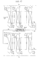
- Figure 17 shows the results of a simulation of the distillation of stable oxygen isotopes using an apparatus in which the number of distillation columns has been increased to 16, and using exactly the same process as the apparatus of Figure 1.
- Table 10 Feed (liquid) flow rate (mol/s) 0.1 16 O 17 O concentration ( 17 O atomic fraction) ppm 738 (370) 16 O 18 O concentration ( 18 O atomic fraction) ppm 4070 (2040)
- Product vapor 1 (collected at bottom of 11 th column) flow rate (mol/s) 8.0 ⁇ 10 -6 16 O 17 O concentration ( 17 O atomic fraction) % 49.6 (24.8) 16 O 18 O concentration ( 18 O atomic fraction) % 36.7 (18.4)
- Product vapor 2 (collected at bottom of 16 th column) flow rate (mol/s) 1.65 ⁇ 10 -4 16 O 17 O concentration ( 17 O atomic fraction) % 3.8 (1.9) 16 O 18 O concentration ( 18 O atomic fraction) % 96.0 (48.2) * The specifications for this
- the present embodiment has the object of obtaining a product which is enriched in the intermediate component of 16 O 17 O, and is a case in which the total height of the distillation column has been increased.
- Figure 17 shows a composition distribution for each of the oxygen isotopes within the column and, in this embodiment, a peak of the 16 O 17 O is apparent in the vicinity of the tenth to twelfth columns, therefore, it is possible to obtain a 16 O 17 O enriched product by means of collecting vapor liquid from at least one place in these columns.
- vapor is collected from the bottom (the outlet of the reboiler) of the eleventh column as product vapor 1.
- vapor drawn off from the bottom of the sixteenth column is collected as product vapor 2.
- the concentration of 16 O 17 O in product 1 is approximately 50%, however, if the total height of the distillation column is increased further, it is possible to obtain further enriched 16 O 17 O.
- oxygen which has been purified to 99.999% or greater is supplied to the first column as feed.
- the amount of 16 O 17 O in the feed is 738 ppm, and the amount of 16 O 18 O is 4070 ppm.
- the product vapor 1 is collected form the bottom of the eleventh column. If this product vapor 12 is processed in a hydrogenation apparatus in order to obtain water in its normal form, heavy oxygen water having a concentration of 17 O of approximately 25%.
- Product vapor 2 is collected from the bottom of the sixteenth column. If this is processed in a hydrogenation apparatus, heavy oxygen water having a concentration of 18 O of approximately 48% is obtained.
- a distillation column having a total height shorter than the present example can be used.
- the composition for the peak of 16 O 17 O is approximately 1%. More specifically, if the composition distribution of 16 O 18 O of Figure 17 is considered, from the first column to vicinity of the sixth column, the slope of the composition is small, and in order to enrich 16 O 17 O to a high concentration, it is necessary to increase the total height beyond that necessary for 16 O 18 O in the present example. In other words, if the total packing height is increased, it is possible to enrich the intermediate components using the apparatus of the present invention.
Landscapes
- Engineering & Computer Science (AREA)
- Physics & Mathematics (AREA)
- Mechanical Engineering (AREA)
- Thermal Sciences (AREA)
- General Engineering & Computer Science (AREA)
- Chemical & Material Sciences (AREA)
- Chemical Kinetics & Catalysis (AREA)
- Separation By Low-Temperature Treatments (AREA)
- Vaporization, Distillation, Condensation, Sublimation, And Cold Traps (AREA)
- Oxygen, Ozone, And Oxides In General (AREA)
Description
- The present invention relates to an apparatus for separation/enrichment of isotopes of a uniform compound, and to an apparatus and method for obtaining heavy oxygen water in which the oxygen isotopes 17O and 18O (referred to as heavy oxygen isotopes) within the water molecules have been enriched. More specifically, the present invention relates to a method of producing water enriched in the oxygen isotopes of 17O and 18O in which oxygen is enriched in 16O17O, 16O18O, 17O17O, 17O18O, and 18O18O by cryogenic distillation of oxygen, and then converted to water, and to a method of producing water which is further enriched in the oxygen isotopes of 17O and 18O in which oxygen is enriched in 16O17O , 16O18O, 17O17O , 17O18O and 18O18O by cryogenic distillation of oxygen, and then converted to water which is then subj ect to water distillation.
- In the distillation operation in a system in which the relative vapor pressure (separation factor) is extremely small, as represented by the process of distillation separation/enrichment of isotopes, an extremely large theoretical number of plates is necessary.
- In this case, generally, packed columns are used in order to suppress pressure loss within the column, however, it is not uncommon for the required packing height therefor to reach several hundred meters.
- Consequently, actual apparatuses are constructed with a plurality of distillation columns connected by piping, the whole of which comprises a single distillation column group.
- Figure 18 shows an example of an apparatus provided with three distillation columns with each of the columns (first to
third columns - In this apparatus, the liquid which accumulates in the bottom of the
first distillation column 61 and thesecond distillation column 62 is supplied by means ofpumps second distillation column 62 andthird distillation column 63 respectively as reflux liquid. Vapor which is drawn off from the top of thesecond column 62 and thethird column 63 is returned to the bottoms of thefirst column 61 and thesecond column 62 respectively as ascending vapor. - In this process, the supply of the process fluid from the
first column 61 to thesecond column 62 and from thesecond column 62 to thethird column 63 is carried out byliquid pumps second column 62 to thefirst column 61, and from thethird column 63 to thesecond column 62 occurs due to the pressure differences in the vapor. Therefore, the pressure within the distillation columns must be successively higher from thefirst column 61 toward thethird column 63. In general, since the relative vapor pressure (separation factor) is smaller the higher the operating pressure of the distillation column, distillation efficiency is lower in thesecond column 62 than thefirst column 61, and lower in thethird column 63 than in thesecond column 62. - In addition, in general, as in isotope separation processes, when the relative vapor pressure of the separation components is extremely small and the packing height is extremely large, the time (hereinafter referred to as the start-up time) from the start up of the apparatus until it becomes possible to collect the stipulated amount (the product amount extracted in accordance with the specifications, or the planned value) may take from
several month 5 to several years. Consequently, reduction of the start-up time has hitherto been an issue. - The start-up time is heavily dependent on the process liquid hold-up within the apparatus, and the greater the amount thereof, the longer the start-up time is.
- Figure 19 shows a distillation process havinglalthe same functions as the apparatus shown in Figure 18, and each
column condensers reboilers column 71 to which the starting material is fed to thecolumn 73 which is downstream fromcolumn 71. - Thereby, it is possible to reduce the process liquid hold-up within the apparatus, and to shorten the start-up time.
- However, even when using this type of apparatus, since the pressure within the distillation column increase from the
first column 71 to thethird column 73, in the same way as with the apparatus shown in Figure 18, the distillation efficiency is lower in thesecond column 72 than in thefirst column 71, and is lower in thethird column 73 than in thesecond column 72. - Reductions in the distillation efficiency are led to increases in the necessary packing height of the distillation column and to increases in the process liquid hold up, therefore, they are not desirable from the point of view of shortening the start-up time.
- In addition, in conventional isotope distillation processes, columns packed using unstructured packing have been used. In general, unstructured packing has a larger specific surface area compared with structured packing, however, the liquid hold-up within the distillation column is 10 to 20% of the volume of the column, and in some cases exceeds 20%, and this is a cause of prolonged start-up time.
- This is accomplished by means of the apparatus of
claim 1 or according to the preferred embodiments of the dependent claims. - In consideration of the above-mentioned circumstances, the present invention has as an object the provision of an apparatus comprising a plurality of distillation columns and with which the start-up time is shorter than with conventional apparatuses.
- In these apparatuses it is possible to set the pressure in each column lower than in conventional apparatuses, to increase the relative vapor pressure between each of the isotopes within each column, and thereby it is possible to improve distillation efficiency.
- Consequently, it is possible to reduce the height of the packing within each column, and it is possible to shorten the start-up time. In addition, it is possible to obtain a product having a higher concentration of heavy oxygen isotopes.
- In addition, the liquid hold-up volume is reduced, and this makes it possible for the start-up time of the device to be reduced even further.
-
- Figure 1 is a schematic structural diagram showing an example of a first embodiment of the apparatus of the present invention.
- Figure 2 is a perspective view showing an example of non-promoting-fluid-dispersion type structured packing which can be used in the apparatus of the present invention.
- Figure 3 is a perspective view showing another example of non-promoting-fluid-dispersion type structured packing which can be used in the apparatus of the present invention
- Figure 4 is a perspective view showing an example of promoting-fluid-dispersion type structured packing which can be used in the present invention.
- Figure 5 is a perspective view showing another example of promoting-fluid-dispersion type structured packing which can be used in the present invention.
- Figure 6 is a perspective view showing yet another example of promoting-fluid-dispersion type structured packing which can be used in the present invention.
- Figure 7 is a schematic structural drawing showing a second embodiment (not according to the present invention)
- Figure 8 is a schematic structural drawing showing a third embodiment of the apparatus (not according to the present invention)
- Figure 9 is a schematic structural diagram showing a modified example of the apparatus shown in Figure 8.
- Figure 10 is a schematic structural diagram showing another embodiment of the apparatus (not according to the present invention.)
- Figure 11 is a schematic structural diagram showing the circulation system for a medium for heat exchange which is used in the apparatus shown in Figure 10.
- Figure 12 is a schematic structural diagram showing yet another example of the apparatus (not according to the present invention).
- Figure 13 is a schematic structural diagram showing a hydrogenation device of the apparatus shown in Figure 12.
- Figure 14 is a schematic structural diagram showing yet another embodiment of the apparatus (not according to the present invention)
- Figure 15 is a schematic structural diagram showing an example of an isotope scrambler which is used in the apparatus shown in Figure 14.
- Figure 16 is a graph showing the results of a simulation of the enrichment of heavy oxygen isotopes for a case in which the apparatus shown in Figure 14 is used as an example, and shows the concentration distribution for each isotope within each column. In this graph, the horizontal axis shows the total packing height, and the vertical axis shows the concentration of each isotope.
- Figure 17 is a graph showing the results of a simulation of the enrichment of heavy oxygen isotope for a case in which an apparatus is used which employs the same structure as the apparatus shown in Figure 1 with the exception that the number of distillation columns is 16, as an example. This graph shows the concentration distribution for each isotope with each column. In this graph, the horizontal axis shows the total packing height, and the vertical axis shows the concentration distribution for each isotope.
- Figure 18 is a schematic structural diagram showing an example of a conventional apparatus.
- Figure 19 is a schematic structural diagram showing another example of a conventional apparatus.
- Figure 1 shows a first embodiment of the apparatus of the present invention. The apparatus shown here is equipped with three distillation columns, a
first column 1, asecond column 2, and athird column 3, constructed in a cascade. - Here, constructed in a cascade means that the distillation columns are connected in such a way that the enriched product of one column can be further enriched in the next distillation column, and then can be further enriched again in the next distillation column, and all the distillation columns together constructed in this way are referred to a cascade process.
- In addition, in the figure, path indicated by the broken line is a modification of the present embodiment, and is not included in the apparatus of the present embodiment.
- A
first condenser 5, asecond condenser 7, and athird condenser 9 which cool and liquefy at least a part of the vapor drawn off from the tops of thefirst column 1, thesecond column 2, and thethird column 3 respectively are provided in the vicinity of the tops of these first tothird columns -
Condensers first conduits column second conduits - As
condensers - In the example shown in the Figures,
condensers columns columns - A
first reboiler 6, asecond reboiler 8, and athird reboiler 10 which heat and vaporize at least a part of the liquid drawn off from the bottom of thecolumns columns -
Reboilers first conduits columns second conduits - As
reboilers - In the example shown in the Figures, the
reboilers columns columns - In the distillation column of the present invention, the outlet (the outlet of
first conduit 6a) ofreboiler 6 of the first column which is provided in the vicinity of the bottom of thefirst column 1, and the inlet of thecondenser 7 of the second column which is provided in the vicinity of the top of the second column are connected by afirst introduction conduit 12 via avalve 12v. - In the same way, the outlet (outlet of
first conduit 8a) of thereboiler 8 of the second column, and the inlet (the inlet of thefirst conduit 9a) of thecondenser 9 of the third column are connected bysecond introduction conduit 13 viavalve 13v. - In addition, the outlet (the outlet of first conduit 7a) of the
condenser 7 of the second column and the inlet (the inlet of thefirst conduit 6a) of thereboiler 6 of the second column are connected by means of thefirst return conduit 14 viavalve 14v. - In addition, the outlet (the outlet of
first conduit 9a) of thecondenser 9 of the third column and the inlet (the inlet of thefirst conduit 8a) of thereboiler 8 of the second column are connected by means of thesecond return conduit 15 viavalve 15v. - The position of installation of
valve 14v andvalve 15v is in the upper part (close to the condenser) ofreturn conduits - The insides of the first to
third columns - As this structured packing 11, non-promoting-fluid-dispersion type structured packing and/or promoting-fluid-dispersion type structured packing can be suitably used.
- Non-promoting-fluid-dispersion type structured packing has a shape and structure with which the liquid descending within the distillation column and the vapor ascending within the distillation column flow in opposition to one another along the surface of the packing, and vapor-liquid contact occurs without the promotion of mixing of the liquid and vapor in the horizontal cross-section direction with respect to the column axis. As examples, a packing material in which a large number of plates formed from aluminum, copper, alloy of aluminum and copper, stainless steel, various types of plastic, or the like are positioned parallel to the direction of the main flow (the direction of the column axis) can be mentioned.
- Here, the main flow indicates the descending liquid and the ascending vapor which occurs along the direction of the column axis within the distillation column, therefore, it indicates the flow in the direction of the column axis with respect to the flow of mass transfer which is produced at the liquid-vapor interface (in other words, the boundary layer) at the surface of the packing.
- Examples of typical non-promoting-fluid-dispersion type packing materials are shown in Figure 2 and Figure 3.
- The non-promoting-fluid-dispersion type structured packing 51 shown in Figure 2 has a honeycomb structure comprising plates parallel to the direction of the axis of the column.
- In addition, the non-promoting-fluid-dispersion type structured packing 52 shown in Figure 3 is a lattice structure comprising a plurality of mutually
parallel plates 52a and a plurality ofplates 52b which are arranged at right angles with respect to theplates 52a, and this lattice structure is positioned along the direction of the column axis. - Promoting-fluid-dispersion type structured packing has a shape and structure with which vapor-liquid contact occurs mainly on the surface of the above-mentioned structured packing between the liquid descending within the distillation column and the vapor ascending within the distillation column, at which time, the liquid and the vapor flow in opposition to one another on the surface of the above-mentioned structured packing in the direction of the main flow which is along the direction of the column axis, and at the same time, mixing of the liquid and/or the vapor in a direction at right angles to the above-mentioned main flow direction is promoted and vapor-liquid contact occurs. These are called structured packing or regular packing in which thin plates of aluminum, copper, aluminum-copper alloy, stainless steel, various plastics, or the like are formed into a variety of regular forms, and then made into a laminated block.
- Examples of typical promoting-fluid-dispersion type packing materials are shown in Figure 4 to Figure 6.
- In the promoting-fluid-dispersion type structured packing 53 shown in Figure 4, a plurality of wave-shaped thin plates are disposed parallel to the column axis and made into the form of a block by layering the plates so that they come into contact with one another. The wave-shaped grooves in each of the thin plates are inclined with respect to the column axis, and neighboring wave-shaped thin plates are disposed so that the direction of their wave-shaped grooves intersect one another. In addition, a plurality of
holes 53a are provided in the thin plates. When the thin plates are disposed perpendicular with respect to the horizontal plane, the holes are provided with an interval of spacing there between and form a plurality of rows along a direction which is at right angles to the column axis. - Figure 5 shows an example of a structural unit of another promoting-fluid-dispersion type structured packing. In the promoting-fluid-dispersion type structured packing 54 shown here, a thin plate is molded pressed in a wave shape to form wave-shaped grooves. In addition, this example has the feature that extremely small wave-shaped
grooves 54b are formed in the thin plates at a fixed angle with respect to the wave-shaped grooves. In addition,reference 54a indicates holes formed in the thin plate. - The promoting-fluid-dispersion type structured packing 55 shown in Figure 6 has the feature of having a structure in which sections having extremely
small grooves 55b formed at a fixed angle with respect to the wave-shaped grooves and smooth sections which do not have these extremely small grooves are provided alternately in the wave-shaped thin plate. In addition, thereference 55a indicates holes formed in the thin plates. - In the following, an example of a first embodiment of the method for enrichment of heavy oxygen isotopes of the present invention will be explained in detail using, as an example, a situation in which the apparatus shown in the above-mentioned Figure 1, being an example of a first embodiment of the apparatus of the present invention, is used.
- Firstly, an oxygen starting material is supplied to the inside of the
first column 1 asfirst column feed 101 via aconduit 20 which serves as a feeding section connected to thefirst distillation column 1 at a position intermediate (intermediate position in the height direction). - The use of oxygen with high purity is preferred as the above-mentioned oxygen vapor starting material. As the above-mentioned oxygen of high purity, it is possible to use oxygen with a purity of 99.999% or higher, from which impurities such as argon, hydrocarbons, krypton, xenon, and fluorine compounds (such as perfluorocarbons) have been removed in advance. In particular, the use of an oxygen starting material from which hydrocarbons have been removed is preferable from the point of view of safety.
- The oxygen starting material vapor supplied to the
first column 1 is distilled by means of vapor-liquid contact with a reflux liquid (i.e., descending liquid) described below, when ascending within thefirst column 1 and passing through the packing 11. - The oxygen molecules in the oxygen starting material vapor which contain heavy oxygen isotopes (i.e., 16O17O, 16O18O, 17O17O, 17O18O, and 18O18O) are more likely to condense due to their high boiling points, and in the process of vapor-liquid contact, the concentration of heavy oxygen isotopes in the descending liquid increases, and the concentration of heavy oxygen isotopes in the ascending vapor decreases.
- The ascending vapor which reaches the top of the column and which has a reduced concentration of heavy isotopes is drawn off from the
column 1 viaconduit 21, and is divided into two parts. One part is introduced into thefirst conduit 5a of thefirst column condenser 5 where it is exchanges heat with the medium for heat exchange flowing within thesecond conduit 5b, condenses, and is returned to the top ofcolumn 1 as reflux liquid. The other part is discharged out of the system asexhaust vapor 103 through theconduit 22. - The reflux liquid returned to the top of the
first column 1 flows down as descending liquid over the structure packing 11 while making vapor-liquid contact with the oxygen starting material vapor and the below-mentioned ascending vapor which are ascending within thecolumn 1, and reaches the bottom of thecolumn 1. - In this process of vapor-liquid contact, the descending liquid becomes enriched in heavy oxygen isotopes (i.e. 16O17O, 16O18O, 17O17O, 17O18O, and 18O18O), which have a greater tendency to liquefy.
- Liquid which reaches the bottom of the first column 1 (hereinafter, the liquid which accumulates at the bottom of each of the columns is referred to as the "column bottom liquid") is drawn off from the
column 1 throughconduit 23, and is combined with the below-mentionedfirst return liquid 107 in the above-mentionedfirst return conduit 14, and then introduced into thefirst conduit 6a of thefirst column reboiler 6, where it is vaporized by heat exchange with the medium for heat exchange flowing within thesecond conduit 6b, and then drawn off from thereboiler 6 via the above-mentionedfirst introduction conduit 12 as firstcolumn output vapor 102 which is an enriched material enriched in heavy oxygen isotopes. - A part of the first
column output vapor 102 drawn off fromreboiler 6 is returned to the lower part of thefirst column 1 viaconduit 24, and rises within thecolumn 1 as ascending vapor. The other part passes alongfirst introduction conduit 12 as secondcolumn feed vapor 104, is combined with the below-mentioned second columntop vapor 106, and introduced into thesecond column condenser 7. Here, it condenses, drawn off from thecondenser 7 via thereturn conduit 14 and then divided into two parts. - One part of this divided condensed liquid passes along
return conduit 14, throughvalve 14v, and is combined with the above-mentioned first column bottom liquid asreturn liquid 107, then it is introduced into the above-mentionedfirst column reboiler 6. - The return of this
return liquid 107 occurs due to the weight of the condensed liquid itself which was liquefied in thecondenser 7, flows out, and descends withinconduit 14. - According to the method of the present embodiment, a part of the condensed liquid which has passed through the
second column condenser 7 is returned to thefirst column reboiler 6 asfirst return liquid 107, and the return liquid under its own weight (head pressure) is introduced into thefirst column 1 by passing through thereboiler 6, therefore, the pressure within the top of thesecond column 2 can be made to be lower than the pressure of the bottom of thefirst column 1. - Therefore, it is possible for the above-mentioned second
column feed vapor 104 to be sent to thesecond column 2 via theconduits - The other part of the condensed liquid which was divided after being drawn off from the
condenser 7 is supplied to the top of thesecond column 2 as second column reflux liqui throughconduit 25, and flows down as descending liquid while making vapor-liquid contact with the ascending vapor within thesecond column 2 to reach the bottom of thesecond column 2. - In this process of vapor-liquid contact, the concentration of heavy isotopes within the ascending vapor decreases, while the descending liquid becomes further enriched in heavy oxygen isotopes.
- The ascending vapor which reaches the top of the column and which has a reduced concentration of heavy isotopes is drawn off from
column 2 via theconduit 28, and is combined astop vapor 106 with the secondcolumn feed vapor 104 in the above-mentionedintroduction conduit 12. - The column bottom liquid of the
second column 2 which is an enriched material enriched in heavy oxygen isotopes is drawn off from the second column viaconduit 26, is combined with the below-mentionedsecond return liquid 112 in the above-mentionedsecond return conduit 15, and introduced into thesecond column reboiler 8. Here, after being vaporized, it is drawn off from thereboiler 8 via the above-mentionedsecond introduction conduit 13 as secondcolumn output vapor 105 which is enriched material enriched in heavy oxygen isotopes. - A part of the second
column output vapor 105 drawn off fromreboiler 8 is returned to the lower part of thecolumn 2 via theconduit 27, and becomes ascending vapor which ascends within thesecond column 2. The other part passes alongintroduction conduit 13 as thirdcolumn feed vapor 108, is combined with the below-mentioned third columntop vapor 111, and is introduced into thethird column condenser 9. Here, it condenses, is drawn off from thecondenser 9 throughsecond return conduit 15, and is then divided into two parts. - One part of this divided condensed liquid passes along
second return conduit 15, throughvalve 15v, and is introduced into the above-mentionedsecond column reboiler 8 assecond return liquid 112. - The return of this
return liquid 112 occurs due to the weight of the condensed liquid itself which was liquefied in thecondenser 9, drawn off, and descends within theconduit 15. - According to the method of the present embodiment, a part of the condensed liquid which has passed through the
third column condenser 9 is returned to thesecond column reboiler 8 assecond return liquid 112, and this return liquid under its own weight (head pressure) is introduced into thesecond column 2 by passing through thereboiler 8, therefore, the pressure within the top of thethird column 3 can be made to be lower than the pressure of the bottom of thesecond column 2. - Therefore, it is possible for the above-mentioned third
column feed vapor 108 to be sent to thethird column 3 via theconduits - The other part of the condensed liquid which was divided after being drawn off from the
condenser 9 is supplied to the top of thethird column 3 as third column reflux liquid throughconduit 29, and flows down as descending liquid while making vapor-liquid contact with the ascending vapor within thethird column 3 to reach the bottom of thethird column 3. - In this process of vapor-liquid contact, the concentration of heavy isotopes within the ascending vapor decreases, while the descending liquid becomes further enriched in heavy oxygen isotopes.
- The ascending vapor which reaches the top of the column and which has a reduced concentration of heavy isotopes is drawn off from
column 3 via theconduit 33, and is combined astop vapor 111 with the thirdcolumn feed vapor 108 in the above-mentionedintroduction conduit 13. - The column bottom liquid of the
third column 3 which is an enriched material enriched in heavy oxygen isotopes is drawn off from thecolumn 3 viaconduit 30, and introduced into thethird column reboiler 10. Here, after being vaporized, it is drawn off from thereboiler 10 as thirdcolumn output vapor 109 which is enriched material enriched in heavy oxygen isotopes. - This third
column output vapor 109 from thereboiler 10 is divided into two parts. One part is returned to the lower part of thecolumn 3 via theconduit 31. and becomes ascending vapor which ascends within thethird column 3. The other part passes alongconduit 32 and is collected asproduct vapor 110 which is an enriched product enriched in heavy oxygen isotopes. - In the following, the settings for the
feed vapors - The flow rate of the second
column feed vapor 104 is set to obtain a sufficient amount for the flow rate of the desired component accompanying the secondcolumn feed vapor 104 with respect to the flow rate of the desired component accompanying the product (for this embodiment, this is only the product vapor 110) collected to the outside of the apparatus from the second column or the third column. - In more detail, if the flow rate of the desired component accompanying the
product 110 collected to the outside of the apparatus from the second column or third column] divided by [the flow rate of the desired component accompany the second column feed vapor 104] is equal to [the yield of the desired component], it is preferable for the setting to be such that the yield of this desired component to be 1% to 10% or less. - If the amount of the second
column feed vapor 104 is made to be too small (if an attempt is made to make the yield of the desired components greater), the distillation efficiencies of the second column and the third column are reduced. In contrast, if the amount of the secondcolumn feed vapor 104 is made to be too great, the distillation efficiency does not improve very much with respect to the increase in the amount of heat exchange in thefirst column reboiler 6 and thesecond column condenser 7. - In addition, the flow rate of the third
column feed vapor 108 is set to obtain a sufficient amount for the flow rate of the desired component accompanying the thirdcolumn feed vapor 108 with respect to the flow rate of the desired component accompanying the product (for this embodiment, this is only the product vapor 110) recovered to the outside of the apparatus from the third column. - In more detail, if [the flow rate of the desired component accompanying the
product 110 collected to the outside of the apparatus from the third column] divided by [the flow rate of the desired component accompany the third column feed vapor 108] is equal to [a yield of the desired component], it is preferable for setting to be such that the yield of the desired component to be 1 % to 10% or less. - If the amount of the third
column feed vapor 108 is made to be too small (if an attempt is made to make the yield of the desired components greater), the distillation efficiencies of the third column are reduced. In addition, if the amount of the thirdcolumn feed vapor 108 is made to be too great, the distillation efficiency does not improve very much with respect to the increase in the amount of heat exchange in thesecond column reboiler 8 and thethird column condenser 9. - In the following, the operation control method of each of the above-described columns will be explained.
- When considering a given column, there are the following four controllable sections.
- 1. The valve in the piping which supplies vapor from the kth column to the (k + 1)th column.
- 2. The valve in the piping which supplies liquid from the (k + 1)th column to the kth column.
- 3. The amount of heat exchange in the reboiler (the pressure and flow rate of the warm medium)
- 4. The amount of heat exchange in the condenser (the pressure and flow rate of the cold medium)
- It is difficult to adjust all four simultaneously, therefore, basically, in each column, 1 and 3 are fixed and 2 and 4 are adjusted while watching the condition of the apparatus.
- Firstly, the adjustment of 3, the amount of heat exchange in the reboiler (the pressure and flow rate of the warm medium), is carried out in the following way.
- It is maintaining the amount of heat exchange in the reboiler after it has been set in advance so that the vapor load of each column is at a suitable value (planned value). It is preferable for the setting to be such that the density correlated superficial velocity (hereinafter referred to as the superficial F factor) is 0.5 m/s(kg/m3)0.5 or greater and 3.0 m/s(kg/m3)0.5 or less, preferably 0.7 m/s(kg/m3)0.5 or greater and 2.2 m/s(kg/m3)0.5 or less.
- Next, the
valves conduits 12 and 13) which supply vapor from the kth column to the (k+1)th column are adjusted. When the pressure at the tops of each of the columns is approximately equal, the pressure at the bottom of the kth column is greater than the pressure at the top of the (k+1)th column by amount of the pressure loss in the kth column. Consequently, in addition to the provision of a valve in way along of the piping, the flow rate of the vapor supplied from the kth column to the (k+1)th column is measured, and controlled to predetermined flow rate. This flow rate is not a strict one and once a precise and suitable flow rate is established, the degree of opening of the valve is not adjusted. The pressure of each column is constant, this flow rate rarely fluctuates. - Next, (4) the amount of heat exchange in the condenser (the pressure and flow rate of the cold medium) is set. This is set such that the pressure within each of the distillation columns are constant. Since (3) the amount of heat exchange in the reboilers is fixed, if the (4) amount of heat exchange in the condenser is small, the pressure in the distillation columns continues to increase.
- In addition, on the other hand, if the (4) amount of heat exchange in the condensers is large, the pressure in the distillation columns continues to decrease. Even if adjustment is made and an optimal value is achieved at one point in time, the heat entering the apparatus varies due to the weather, and the pressure fluctuates.
- Consequently, it is necessary to control (4) the amount of heat exchange in the condenser while always measuring the pressure in each of the columns.
- Next, (2) the
valves conduits 14 and 15) which returns the liquid to the kth column from the (k+1) th column is adjusted. - The control values 14v and 15v are installed at a position relatively close to the condenser at the top of the column within a range at which it is possible to obtain a prescribed liquid head. This is in order to reduce the liquid hold-up within the piping.
- The degree of opening of these valves is adjusted while measuring the liquid level at the bottom of each columns.
- When the degree of opening is too small, and the amount returned to the kth column from the (k+1)th column becomes small, since the
valves condensers - On the other hand, when the return to the kth column from the (k+1)th column is large, the liquid level at the bottom of the distillation column decreases.
- Consequently, (2) the valve of the liquid piping must be controlled in such a way that the height of the level of the liquid in the bottom of each distillation column is constant.
- In addition, the
valves - In the apparatus of the present embodiment, since the outlet of the
first column reboiler 6 and the inlet of thesecond column condenser 7 are connected by thefirst introduction conduit 12 and the outlet of thesecond column reboiler 8 and the inlet of thethird column condenser 9 are connected by thesecond introduction conduit 13, and since the outlet of thesecond column condenser 7 and the inlet of thefirst column reboiler 6 are connected byfirst return conduit 14; the outlet of thethird column condenser 9 and the inlet of thesecond reboiler 8 are connected by thesecond return conduit 15, it is possible to return a part of the condensed liquid which has passed through thecondensers return liquid reboilers - For this reason, it is possible to set the pressure within
columns - In addition, for the above-mentioned reasons, it is possible to obtain with good efficiency a product containing a high concentration of heavy oxygen isotopes.
- In addition, in conventional apparatuses (Figure 19), all of the supply conduits from an earlier stage column to a later stage column are filled with liquid. In contrast, in the apparatus of the present embodiment, of the return conduits, only the portions corresponding to the liquid head portions which correspond to the difference in pressure of these columns are full of liquid. In other words, of the return conduits from a later stage column to an earlier stage column, only the portions of conduits corresponding to liquid head portions which correspond to the pressure difference of those columns for which the return of the
return liquid condensers - For this reason, the amount of liquid hold-up is reduced, and it is possible for the start-up time for the apparatus to be shortened even more.
- In particular, when the diameter of the distillation columns is small, the diameter of the piping of the return conduits is relative by large, therefore, the difference between the liquid hold-up of the apparatus of the present invention and that of a conventional apparatus is considered to be large. In addition, from the point of view of the start-up time, the superiority of the apparatus of the present invention is considered to be even more obvious.
- In addition, by means of the use of structured packing (promoting-fluid-dispersion type structured packing or non-promoting-fluid-dispersion type structured packing) in
columns - In addition, by means of using promoting-fluid-dispersion type structured packing, it is possible to increase the efficiency of vapor-liquid contact within the columns, and to increase the efficiency of the enrichment in heavy isotopes.
- In the distillation column of the above-described embodiment, the outlet of the
second column condenser 7 and the inlet of thefirst column reboiler 6 are connected by thefirst return conduit 14 and the outlet of thethird column condenser 9 and the inlet of thesecond column reboiler 8 are connected by thereturn conduit 15. However, the apparatus of the present invention is not limited to this, the first conduit can be used to connect the outlet of thesecond condenser 7 and the middle section of thefirst column 1 as shown byreference 14a (the conduit indicated by the broken line), and the second return conduit can be used to connect the outlet of thethird column condenser 9 and the middle section of thesecond column 2 as shown byreference 15a (the conduit indicated by the broken line). - In addition, the
columns - Figure 7 shows a second embodiment of the apparatus of the present invention. The apparatus shown here is different to the apparatus shown in Figure 1 on the following points.
- (1) The outlet of the
first column reboiler 6 and the top of thesecond column 2 are directly connected by means of thefirst introduction conduit 35, such that it is possible for the second column feed vapor 104' which has passed through thefirst column reboiler 6 to be supplied directly to the top of thesecond column 2. - (2) The outlet of the
second column reboiler 8 and the top of thethird column 3 are directly connected by means of thesecond introduction conduit 36, such that it is possible for the third column feed vapor 108' which has passed through thesecond column reboiler 8 to be supplied directly to the top of thethird column 3. - (3) The outlet of the
second column condenser 7 and the bottom of thefirst column 1 are directly connected by means of thefirst return conduit 37, such that it is possible for the return liquid 107' from thesecond column condenser 7 to be returned to the bottom of thefirst column 1. - (4) The outlet of the
third column condenser 9 and the bottom of thesecond column 2 are directly connected by means of thesecond return conduit 38, such that it is possible for the return liquid 112' fromthird column condenser 9 to be returned to the bottom of thesecond column 2. - The conduit indicated by the broken line in the figure is a modification of the apparatus of the present embodiment.
- In the following, an example of a method for enrichment of heavy oxygen isotopes (not according to the present invention) will be explained in detail using, as an example, a situation in which the apparatus shown in Figure 7 is used.
- An oxygen vapor starting material supplied to the inside of the
first column 1 asfirst column feed 101 via aconduit 20 is distilled by means of vapor-liquid contact within thefirst column 1. - The column bottom liquid which has been enriched in heavy oxygen isotopes within the
first distillation column 1 is introduced into thefirst column reboiler 6 through the conduit 23', is vaporized, and is drawn off from thefirst column reboiler 6 as the first column output vapor 102'. - A part of the output vapor 102' is returned to the lower part of the
first column 1 viaconduit 39, and the other part is introduced directly into the top of thesecond column 2 throughfirst introduction conduit 35 as second column feed vapor 104'. - In the
second column 2, the ascending vapor which reaches the top of the column and which has a reduced concentration of heavy oxygen isotopes is drawn off from thesecond column 2 through the conduit 28' as columntop vapor 106. It is condensed in thesecond column condenser 7, and then divided. One part is returned as reflux liquid to the upper part of thesecond column 2 through the conduit 25'. The other part is returned to the bottom of thefirst column 1 as first return liquid 107' through thefirst return conduit 37. - The column bottom liquid which has been enriched in heavy oxygen isotopes within the
second column 2 is introduced into thesecond column reboiler 8 through conduit 26', where it is vaporized, and then drawn off from thereboiler 8 as second column output vapor 105'. - A part of the output vapor 105' is returned to the lower part of the
second column 2 throughconduit 40. The other part is directly introduced into the top of thethird column 3 through thesecond introduction conduit 36 as the third column feed 108'. - In the
third column 3, the ascending vapor which reaches the top of the column and which has a reduced concentration of heavy oxygen isotopes is drawn off from thethird column 3 through the conduit 33' as columntop vapor 111. It is condensed in thethird column condenser 9, and then divided. One part is introduced as reflux liquid to the upper part of thethird column 3 through the conduit 29'. The other part is returned to the bottom of thesecond column 2 as second return liquid 112' through thesecond return conduit 38. - In the apparatus of the present embodiment, it is possible to return a part of the condensed liquid which has passed through the
condensers - In the apparatus of the above-described embodiment, the outlet of the
first column reboiler 6 and the top of thesecond column 2 are connected by means of thefirst introduction conduit 35, and the outlet of thesecond column reboiler 8 and the top of thethird column 3 are connected by means of thesecond introduction conduit 36, in addition, the outlet of thesecond column condenser 7 and the bottom of thefirst column 1 are connected by means of thereturn conduit 37, and the outlet of thethird column condenser 9 and the bottom of thesecond column 2 are connected by means of thesecond return conduit 38. However, the apparatus of the present invention is not limited to this. - For example, it is possible for the first and second introduction conduits to be connected to the middle sections of
columns columns references references - Figure 8 shows a third apparatus (not according to the present invention). The apparatus shown here differs from the apparatus shown in Figure 7 on the following points.
- (1) The conduit 28' which carries the column
top vapor 106 of thesecond column 2 to thesecond column condenser 7 and the bottom of thefirst column 1 are connected by the first return conduit 37' such that a part of thetop vapor 106 of thesecond column 2 can be returned to the bottom of thefirst column 1. - (2) The conduit 33' which carries the
top vapor 111 of thethird column 3 to thethird column condenser 9 and the bottom of thesecond column 2 are connected by the second return conduit 38' such that a part of thetop vapor 111 of thethird column 3 can be returned to the bottom of thesecond column 2. - (3)
Blowers - As
blowers heat exchanges - In the following, a third embodiment of the method for enrichment in heavy oxygen isotopes of the present invention will be explained for a situation in which the apparatus shown in Figure 8 is used as an example.
- In the
second column 2, ascending vapor which reaches the top of the column and in which the concentration of heavy oxygen isotopes is reduced is drawn off fromsecond column 2 through conduit 28' astop vapor 106, and divided. - One part of the
top vapor 106 which has been divided is condensed in thesecond column condenser 7, and is then returned to the top of thesecond column 2 where it becomes reflux liquid for that column. The other part passes through the first return conduit 37' and reaches theblower 41 where it is pressurized, and then returned to the bottom of thefirst column 1 asfirst return liquid 107". - In the same way, the column
top vapor 111 drawn of from the top of thethird column 3 is divided after being drawn off from thethird column 3. One part is condensed in thethird column condenser 9, and then return to the top of the third column to become reflux liquid for that column. The other part passes along the second return conduit 38' and reaches theblower 42 where it is pressurized and then returned to the bottom of thesecond column 2 assecond return liquid 112". - In the apparatus of the present embodiment, since supply for each conduit is in vapor form, and not a liquid form, it is possible to shorten the start-up time in the same way as for the apparatus of the above-mentioned first embodiment. In addition, since the bottom of the columns are connected to the tops of the columns and the tops of the columns are connected to the bottoms of the column respectively, it is possible to obtain a product which has a high concentration of heavy oxygen isotopes.
- In the apparatus of the present embodiment, the outlet of the
first column reboiler 6 and the top of thesecond column 2 are connected by means of thefirst introduction conduit 35, and the outlet of thesecond column reboiler 8 and the top of thethird column 3 are connected by means of thesecond introduction conduit 36, and in addition, the inlet of thesecond column condenser 7 and the bottom of thefirst column 1 are connected by means of the first return conduit 37' and the inlet of thethird column condenser 9 and the bottom of thesecond column 2 are connected by means of the second return conduit 38'. However, the present embodiment is not limited to this. - For example, it is possible for the first and second introduction conduits to be connected to the middle sections of the second and
third columns references - In the above-described embodiment, an apparatus having three distillation columns is shown, however, in the apparatus of the present invention, the number of distillation columns is not limited to this.
- In the apparatus shown in Figure 10 (not according to the present invention), the number of distillation columns is n.
- The apparatus shown here comprises n number of distillation columns A1 to An; condensers B1 to Bn which are provided in the vicinity of the top of these distillation columns A1 to An; reboilers C1 to Cn which are provided in the vicinity of the bottoms of the columns A1 to An; introduction conduits D1 to Dn-1 which connect the outlets of the kth column reboilers Ck provided in the vicinity of the bottoms of the kth columns (1 ≦ k ≦ (n-1)) to the tops of the (k+1)th columns; and return conduits E1 to En-1 which connect the outlets of the (k+1)th column condensers Bk+1 of the (k+1 1)th columns to the bottoms of the kth columns.
- The number n of the distillation columns can be, for example, from 2 to 100.
- In addition, the circulation system for the medium for heat exchange for the reboilers and condensers of the apparatus shown in the above-mentioned Figure 10 is shown in Figure 11.
- As shown in Figure 11, each of the condensers B1 to Bn, and reboilers C1 to Cn are connected by means of the
circulation conduit 81 for the medium for heat exchange. - This
circulation conduit 81 is such that the medium for heat exchange within thestorage tank 82 is drawn off, passes through thepump 83 and the first passage of thesubcooler 84, and is introduced into the condensers B1 to Bn. Then, it passes through the second passage of thesubcooler 84 and reaches the first conduit of theheat exchanger 85. Next, it passes through theblower 86 and the second passage of theheat exchanger 85, is introduced into the reboilers C1 to Cn, and then returned to thestorage tank 82. In addition, thesubcooler 84 is for the purpose of cooling the medium for heat exchange in order to prevent vaporization of the medium for heat exchange prior to it reaching the condensers. - In the same way, in the present invention, the number of distillation columns is not limited to the number shown in the figures for the apparatus of the first embodiment shown in Figure 1, the apparatus of second embodiment shown in Figure 7, and the apparatus of the third embodiment shown in Figure 8, and can be set optionally.
- In addition, the above-described embodiment shows a method for enrichment in the heavy isotopes of oxygen by means of cryogenic distillation of an oxygen starting material. However, the present invention is not limited to this. It is also possible to produce heavy oxygen water by carrying out distillation using water as the starting material and using the apparatus of the above-described embodiments to distill this water to enrich it in at least one type of heavy oxygen water of
H 2 17O, H2 18O , D2 17O, D2 18O, DH17O and DH18O which contain heavy oxygen isotopes. - In this situation, in the same way as in the above-mentioned first embodiment, it is possible to shorten the start-up time. In addition, it is possible to obtain a heavy oxygen water product containing a high concentration of heavy oxygen isotopes.
- Figure 12 and Figure 13 show an apparatus which can be used for carrying out another method of producing heavy oxygen water (not according to the present invention) The apparatus shown here comprises an oxygen distillation column unit F1 for distillation of oxygen which comprises a plurality of distillation columns A1 to An; a water distillation column unit F2 for distillation of water which comprises a plurality of distillation columns A'1 to A'n; and a
hydrogenation reaction device 300A provided between these units F1 and F2. - The distillation column units F1 and F2 may adopt the structure of the apparatus shown in Figure 10.
- The
hydrogenation reaction device 300A shown in Figure 13 comprises abuffer tank 341 for temporarily storing the enriched material (oxygen) which has passed through the oxygen distillation column unit F1; aconduit 44 for introducing the oxygen into thebuffer tank 341; aconduit 343 for introducing hydrogen (or deuterium) supplied from a supply source not shown in the figure; acombustion chamber 344 for reacting the oxygen and hydrogen supplied from theconduits combustor 300 having acontroller 345. - The
combustion chamber 344 comprises aburner 344a for mixing and combusting oxygen and hydrogen supplied into thecombustion chamber 344; aheater 344b for igniting the oxygen-hydrogen mixed gas; and acooling coil 344c for cooling the reactant product (i.e., water vapor). Additionally,reference 344d indicates a discharge opening which is provided for expelling the reactant product (water) of thecombustion chamber 344 via a valve. - The
controller 345 regulates aflow control valve 342b by means of signals based on the flow rate of oxygen measured by an oxygenflow rate detector 342a provided inconduit 342, and thereby thecontroller 345 is able to adjust the supply flow rate of oxygen supplied into thecombustion chamber 344 via theconduit 342. - In addition, the
controller 345 regulates aflow control valve 343b by means of signals based on the flow rate of hydrogen which is measured by a hydrogenflow rate detector 343a provided in theconduit 343, and thereby thecontroller 345 is able to adjust the supply volume of hydrogen supplied into thecombustion chamber 344 via theconduit 343. - Further, references 342c and 343c indicate check valves;
references reference 344e indicates a conduit for discharging the small amount of unreacted gas remaining in thecombustion chamber 344, via a valve. - In the following, an embodiment of the method of producing heavy oxygen water of the present invention will be explained for an example in which the above-described apparatus is used.
- The oxygen starting material is supplied to the oxygen distillation column unit F1, and an intermediate vapor 110' is obtained which is an enriched material enriched in the heavy isotopes of oxygen.
- This intermediate vapor 110' (oxygen vapor) is introduced into the
combustor 300 of thehydrogenation reaction device 300A viaconduit 44 andcontrol valve 44a. - The oxygen introduced into the combustor 300 passes through the
buffer tank 341, and is introduced into thecombustion chamber 344 via theconduit 342 and through theburner 344a. - Simultaneously, the hydrogen supplied from a supply source not shown in the figures is supplied to the
combustion chamber 344 via theconduit 343 and through theburner 344a. - At this point, the
controller 345 performs a calculation based on signal based on a predetermined value and a feedback signal based on the flow rate of oxygen measured by the oxygenflow rate detector 342a. The controller regulates the flowrate control valve 342b by means of a signal resulting from this calculation. In the same manner,controller 345 performs a calculation based on the signal based on a predetermined value and a feedback signal based on the flow rate of hydrogen measured by the hydrogenflow rate detector 343a. The controller regulates the flowrate control valve 343b by means of a signal resulting from this calculation. As a result, the aforementioned oxygen and hydrogen are supplied into thecombustion chamber 344 in volumes which approximate the stoichiometric volume for producing water. - The oxygen and hydrogen supplied to the
combustion chamber 344 are always regulated to a volume which closely approximates the aforementioned stoichiometric volume by means of the aforementioned feedback control. However, despite this, excess supplied gas is regularly discharged via a valve from adischarge conduit 344e, and this prevents the gas from accumulating in thecombustion chamber 344. - In order to further reduce the volume of the exhaust gas, it is preferable to jointly employ an even more precise controlling means, such as a feed-forward controlling method.
- The aforementioned oxygen and hydrogen supplied into the
combustion chamber 344 are mixed by means of theburner 344a, and subsequently, jetted into thecombustion chamber 344, ignited by means of theheater 344b, and reacted with each other to produce water. - Most of the produced water is condensed by the cooling
coil 344c, and subsequently expelled out of thecombustion chamber 344 via thedischarge opening 344d, and introduced into the water distillation column unit F2 throughconduit 45 as producedwater 113. - Since this produced
water 113 is obtained using the intermediate product vapor 110' which is a enriched material in heavy oxygen isotopes it is heavy oxygen water which contains a large amount of heavy oxygen isotopes. - The water distillation column unit F2 has the same structure as the oxygen distillation column unit F1, therefore, in the same way as the enrichment process for heavy oxygen isotopes which occurs in the unit F1, the heavy components within the produced
water 113, that is H2 17O, H2 18O, D2 17O, D2 18O, DH 17O and DH 18O, are enriched within the distillation unit F2 and collected as the heavyoxygen water product 114. - In the apparatus it is possible to shorten the start-up time in the same way as for the above-described first embodiment. In addition, it is possible to obtain a heavy oxygen water product which contains a high concentration of heavy oxygen isotopes. Figure 14 shows another apparatus (not according to the present invention) The apparatus shown here comprises n number of distillation columns A1 to An; condensers B1 to Bn which are provided in the vicinity of the top of these columns A1 to An; reboilers C1 to Cn which are provided in the vicinity of the bottoms of the columns A1 to An; introduction conduits D1 to Dn-1 which connect the outlets of the kth column reboilers Ck provided in the vicinity of the bottoms of the kth columns (1 ≦ k ≦ (n-1)) to the tops of the (k+1)th columns; return conduits E1 to En-1 which connect the outlets of the (k+1 )th column condensers Bk+1 of the (k+ 1)th columns to the bottoms of the kth columns; and
isotope scrambler 47. - The
isotope scrambler 47 is for further enriching the heavy oxygen isotope enriched material enriched by means of the columns A to Ah by means of oxygen isotope scrambling. The inlet side of the isotope scrambler is connected to the bottom of the hth column Ah via theextraction conduit 48, and the outlet side of the isotope scrambler is connected to the middle section of the ith column Al which is at a later stage and adjacent to hth column An via areturn conduit 49. - As the
isotope scrambler 47, in addition to the use of an isotope exchange reaction catalyst, it is possible to temporarily form other compounds from the oxygen molecules, and then subsequently break these compounds down to obtain oxygen molecules. - When using the former of these, as the
isotope scrambler 47, the column bottom vapor of column An which is an oxygen isotope enriched material is brought into contact with an isotope exchange reaction catalyst, to promote isotope exchange reactions discussed below within the enriched material, and thereby it is possible to further increase the concentration of molecules of heavy oxygen isotopes within the enriched material. - In this situation, the
isotope scrambler 47 is provided with a catalytic column (not shown in the figure), and an isotope exchange reaction catalyst which packed inside this catalytic column. - As this isotope exchange reaction catalyst, catalysts containing at least one type selected from the group comprising W, Ta, Pd, Rh, Pt, and Au can be used, for example.
- In addition, as the isotope exchange reaction catalysts, in addition to those mentioned above, it is possible to use a catalyst including at least one type selected from the group comprising Ti-oxide, Zr-oxide, Cr-oxide, Mn-oxide, Fe-oxide, Co-oxide, Ni-oxide, Cu-oxide, Al-oxide, Si-oxide, Sn-oxide, and V-oxide. In addition it is possible to use one of either of the above-mentioned single catalysts or the above-mentioned metal oxide catalysts or to use a mixture of a plurality of them.
- As the
isotope scrambler 47, when the later is being used, the column bottom vapor of column Ah which is a heavy oxygen isotope enriched material is temporarily converted to a different compound (for example, water), this is subsequently broken down to give molecular oxygen, and thereby the concentration of molecules of heavy oxygen isotope molecules within the enriched material is further increased. An example of the isotope scrambler used in this method is shown in Figure 15. - In Figure 15, the
isotope scrambler 47 comprises anargon circulation blower 87, acatalytic column 88 packed with an oxidation reaction catalyst, an electriccatalytic cracker 89, and anoxygen purifier 90. - As the oxidation reaction catalyst which is packed in the
catalytic column 88, a catalyst comprising at least one component selected from among the group comprising Pd, Pt, Rh, Ru, Ni, Cu, and Au can be used. In addition, it is possible to use one or more selected from the group comprising catalysts in which Pd, Pt, Rh, Ru, or the like, are carried by one of Al-oxide, Si-oxide, Ti oxide, Zr oxide, Cr oxide, V oxide, Co oxide or Mn oxide. - The
argon circulation blower 87 is provided in order to circulate the gas within the argon circulation system having acatalytic column 88, a cooler 91, and achiller 92. Since oxygen and hydrogen coexist within this circulation system, in consideration of the explosibility range, anargon supply conduit 98 for supplying argon for diluting the vapor within the circulation system is connected to the circulation system. - In addition, this circulation system is provided with a
hydrogen supply conduit 97 for the purpose of maintaining the concentration of hydrogen at the outlet of thechiller 92 at approximately 2%. - Next, an embodiment of the method for enriching oxygen isotopes of the present invention will be explained for a situation in which the above-mentioned apparatus is used as an example.
-
Feed 101 is supplied to first column A1 throughconduit 20, and, thereafter, it is enriched in heavy oxygen isotopes by following the above-described process until it reaches the column An, and thereby a column bottom liquid of column An which is an enriched material is obtained. - Next, this column bottom liquid is introduced to the
isotope scrambler 47 asintroduction oxygen 115 through theconduit 48. - The oxygen supplied to the suction side of the
argon circulation blower 87 from theconduit 48 is mixed with argon and hydrogen, pressurized to approximately 80 to 100 kPa (gauge) by theblower 87, and then introduced into thecatalytic column 88. In addition, at the discharge of the above-mentionedblower 87, small amounts of hydrogen (the part removed from the reaction at thecatalytic column 95 discussed below) are supplied from theconduit 97. In thecatalytic column 88, the hydrogen and the oxygen are reacted to produce water (2H2 + O2 →2H2O and the composition at the outlet of thecatalytic column 88 is approximately 2% hydrogen, approximately 0.5% water vapor, and 97.5% argon. - This mixture is cooled by means of the cooler 91 and the
chiller 92, and the water is separated into thestorage tank 93. This water is sent to the electrolysis tank 94 (pressure 400 kPa gauge) by means of a pump provided within theelectrolysis apparatus 89, undergoes electrolysis, and is separated into hydrogen containing a small amount of oxygen and oxygen vapor containing a small amount of hydrogen again. The former hydrogen vapor is recovered from the above-described argon circulation system. The small amounts of hydrogen and water in the latter oxygen vapor are removed by means of anoxygen purifier 90 which has acatalytic column 95 and anadsorber 96, and the oxygen is drawn off throughconduit 49 and returned to the oxygen distillation column. - In order to prevent loss of oxygen which is enriched in heavy oxygen isotopes within the regenerate gas of the
adsorper 96, separate super high purity oxygen gas (oxygen having the same specifications as the first column feed vapor of the distillation column) is used. - In addition, the flow rate of the isotope scrambler return
oxygen 116 is extremely low compared with the amount of the ascending vapor within the distillation column to which the oxygen is returned. Therefore, it has almost no influence on the distillation efficiency even if it is returned into the distillation column as it is at normal temperature. - When the whole apparatus of the
isotope scrambler 47 is considered, since there are only theconduit 49 for the purified isotopescrambler return vapor 116, and the outlet for the super high purity oxygen which is supplied separately for the purpose of regeneration in theadsorber 96, the other gases circulate within the apparatus and there is almost no loss of gas. Consequently, the amount of the hydrogen and argon which are supplied by the supply line for hydrogen vapor and argon is extremely small. - Within the
catalytic column 88 of theisotope scrambler 47, oxygen and hydrogen are reacted due to the oxidation reaction catalyst and water is produced. For example, if A, B, C, and D are, respectively, any one of the isotope atoms 16O, 17O, and 18O, the atoms which make up the oxygen molecules are separated into different molecules of water by means of reactions like the following:
2H2 + AB → H2A + H2B;
or
2H2 + CD → H2C + H2D;
or
2H2 + AA → H2A + H2A
The relative abundance of each of the heavy oxygen isotopes within the reaction product (the water molecules) obtained thereby is determined by the relative abundance of each of the isotopes within theintroducer oxygen 115. - In addition, within the
electrolysis apparatus 89 of the isotope scrambler, the water molecules are broken down into the oxygen molecules and to hydrogen molecules by means of electrolysis. In the same way, if A, B, C, and D are, respectively, any one of the isotope atoms 16O, 17O, and 18O, the water molecules are broken down into oxygen molecules and hydrogen molecules by means of reactions like the following:
H2A + H2C → 2H2 + AC;
or
H2B + H2D → 2H2 + BD;
or
2H2C → 2H2 + CC
The combination of the oxygen atoms which make up the oxygen molecules obtained here are determined randomly by the relative abundance of the oxygen isotopes present in the water molecules. - In addition, when a plurality of types of isotope molecules are present as described above, each molecule randomly exchanges the coupled atoms from which it is formed is called "isotope scrambling", and the apparatus in which this takes place is called an "isotope scrambler".
- When a method using an isotope exchange reaction catalyst is used as the above-mentioned
isotope scrambler 47, an isotope exchange reaction occurs within the catalytic column of theisotope scrambler 47 due to the isotope exchange reaction catalyst. - Isotope exchange is a reaction wherein coupled atoms in a two-atom molecule are exchanged with other atoms on the surface of a sufficiently heated catalyst.
- In other words, if, for example, A, B, C, and D are, respectively, any one of the isotope atoms, 16O, 17O, and 18O, isotope exchange is a reaction in which:


- If a particular isotope atom is considered, after sufficient time has passed, an isotope atom which couples to form a molecule is randomly determined according to the abundance ratio of each isotope constituent prior to isotope exchange.
- Accordingly, the abundance ratio of each isotope in the reactant material (i.e., oxygen isotope molecule) obtained by means of isotope exchange by means of the
isotope scrambler 47 is determined according to the abundance ratio of each isotope in theintroducer oxygen 115. - In other words, for example, the components of 16O16O, 16O17O, and 16O18O are present in the
output vapor 115. If the respective molar ratios of these components is Y11, Y12, and Y13, the combination of oxygen atoms which make up the oxygen molecules changes randomly based on the abundance probability of each of the isotopes by means of theisotope scrambler 47 using either of the above-described methods, the concentration of each component after the isotope scrambling is as follows:





- A part of the 16O which is contained in the 16O17O and 16O18O becomes 16O16O, and accompanying this the concentration of oxygen molecules (18O18O, 17O18O and 17O17O, hereinafter referred to as heavy oxygen molecules) consisting of the heavy components (17O and 18O) increases.
- The reaction product in which the concentration of heavy oxygen molecules has been increased using the
isotope scrambler 47 is supplied to column Al throughconduit 49 as isotope scrambler returnoxygen 116, and thereafter passes through columns Al to An. - The heavy oxygen molecules have a higher boiling point and are easily enriched, therefore, the concentration of heavy oxygen isotopes is further increased in this process.
- In the enrichment method of oxygen isotopes of the above-described embodiment, it is possible to shorten the start-up time in the same way as in the above-described first embodiment.
- In addition, the heavy oxygen isotope enriched material obtained by means of columns Al to An is supplied to the
isotope scrambler 47, the concentration of heavy oxygen molecules within the enriched material is increased by means of isotope scrambling which occurs in theisotope scrambler 47, the enriched material is then supplied to the columns Al to An, and the concentration of heavy oxygen isotopes is further increased. Therefore, it is possible to obtain a product containing a high concentration of heavy oxygen isotopes. - In addition, the apparatus shown in the figure has a structure in which the
conduit 49 on the outlet side of theisotope scrambler 47 is connected to the ith column Ai. In this way, the column to which theconduit 49 on the outlet side of theisotope scrambler 47 is connected is preferably further down stream (to the later stage side) from the hth column An to which theconduit 48 on the inlet side of theisotope scrambler 47 is connected. However, the present invention is not limited to this, and the column to which theoutlet side conduit 49 is connected may be the column to which theinlet side conduit 48 is connected or may be upstream (to the earlier stage side) from that column. - In other words, the
isotope scrambler 47 can be inserted at any part of "the apparatus constructed from a plurality of distillation columns" which is constructed in a cascade. For example, it is possible to draw off vapor from any place of the kth column (including the distillation column, the condenser, the reboiler, the piping, etc.) process it in the isotope scrambler, and return it to any place of the jth column (including the distillation column, the condenser, the reboiler, the piping, etc.). Here, the size relationship between k and j is unrestricted, and it is also possible for the k and j to be equal. However, in order for the isotope scrambling to be conducted efficiently, the place at which the vapor is extracted from the apparatus is preferable a position at which 16O18O is most enriched. In addition, it is preferable for the position to which the vapor is returned to the distillation column after isotope scrambling to be at a later stage (location at which the 18O18O is more enriched) than the place of extraction, because the concentration of 18O18O in the gas after the isotope scrambling is greater than the concentration of the isotope 18O18O at the position of extraction. - In addition, in the present invention, it is possible to obtain heavy oxygen water by means of supplying oxygen extracted from the above-mentioned final column An to the above-mentioned
hydrogenation reaction apparatus 300, and converting it to water. - Next, the results of computer simulations for situations in which enrichment in heavy oxygen isotopes was conducted using each of the above-mentioned apparatuses will be explained.
- The distillation theory employed in designing the distillation column according to the present invention and the distillation theory employed in this simulation use a rate model relating to mass transfer, in which the so-called H.E.T.P. (Height Equivalent to a Theoretical Plate) or equilibrium stage model were not used.
- In the distillation theory using this rate model, the mass flux N is expressed in the following way using the diffusion flux J and convection p v.

- In addition, as the formula for the correlation related to mass transfer, it is possible to give the following.

wherein Sh, Re, and Sc are respectively defined by the following formulae.


- N: mass flux [kg/(m2·s)]
- J: diffusion flux [kg/(m2·s)]
- d: equivalent diameter [m]
- D: diffusion coefficient [m2/s]
- p: density [kg/m3]
- v: velocity [m/s]
- ω: concentration [kg/kg]
- Sh: Sherwood number [-]
- Re: Reynolds number [-]
- Sc: Schmidt number [-]
- subscript G: vapor phase
- subscript S: vapor-liquid interface
- The advantages with this rate model are that it is possible to correctly predict the mass transfer of an intermediate component within a multi-component system, and it does not give unrealistic results such as the negative values obtained with H.E.T.P. or Murphree's plate efficiency which occur when making calculations by means of the equilibrium stage model.
- The aforementioned model is disclosed in detail in J.A. Wesselingh: "Non-equilibrium modeling of distillation" IChemE Distillation and Absorption '97, vol. 1, pp. 1-21 (1997).
- Table 2 shows the results of a simulation conducted using the above-mentioned model for a situation in which enrichment in oxygen isotopes was carried out using the enrichment apparatus shown in Figure 1. The specifications for the apparatus are shown in Table 1.
- The results of a simulation conducted for a situation in which the enrichment in oxygen isotopes was carried out using the conventional apparatus shown in Figure 19 are shown together in Table 2.
- In this conventional apparatus the diameter of the first through third columns and the packing height were assumed to be the same as in the apparatus of Example 1. In addition, the amount of feed, the amount of product, the reflux ratio, and the like were also given the same values as for Example 1.
Table 1 First Column Second Column Third Column Packing height (m) 150 150 150 Internal diameter of Column (m) 0.4 0.2 0.08 Specific surface area of packing (m2/m3) 500 500 500 Table 2 Conventional Example 1 Example 1 First Column Condenser Amount of heat exchange (kW) 109.6 109.6 Feed Flow rate (mol/s) 1.0 (vapor) 1.0 (vapor) Pressure (kPa) 120 120 16O18O concentration (ppm) 4070 4070 Ascending vapor Flow rate (mol/s) 16.4 16.4 Reboiler Amount of heat exchange (kW) 106.0 113.2 Second Column Condenser Amount of heat exchange (kW) 24.2 31.7 Feed Flow rate (mol/s) 0.53 (liquid) 0.53 (vapor) Pressure (kPa) 156 120 16O18O concentration (%) 2.29 2.01 Ascending vapor Flow rate (mol/s) 4.2 4.2 Reboiler Amount of heat exchange (kW) 27.2 28.6 Third Column Condenser Amount of heat exchange (kW) 3.8 5.0 Feed Flow rate (mol/s) 0.084 (liquid) 0.084 (vapor) Pressure (kPa) 193 122 16O18O concentration (%) 16.9 15.2 Ascending vapor Flow rate (mol/s) 0.668 0.668 Column bottom product Flow rate (mol/s) 4.0 × 10⁻⁴ (vapor) 4.0 × 10⁻⁴ (vapor) Pressure (kPa) 230 160 16O18O Concentration (-) 65.0 67.6 Reboiler Amount of heat exchange (kW) 4.4 4.5 16O18O hold-up Packing layer/condenser/reboiler (mol) 865 803 Liquid supply piping (mol) 109 2.2 Total (mol) 974 805 Start-up Time (days) 39 30 - From Table 2 it can be seen that the concentration of 16O18O in the product is higher for the method of Example 1 in which the apparatus of Figure 1 was used than in the method of Conventional Example 1 in which a conventional apparatus was used.
- This can be considered to be due to the fact that it is possible for the situation in Example 1 to reduce the pressure within the columns compared with Conventional Example 1. and as a result it is possible to increase the relative vapor pressure of each of the components within the column and to improve the efficiency of the distillation.
- In addition, from Table 2, it can be seen that it is possible to shorten the start-up time of the apparatus. This is considered to be due to the following reasons.
- In Conventional Example 1, almost all of the sections of the piping which is the liquid supply conduits between the first column and the second column and between the second column and the third column are full of liquid. In contrast, in Example 1, of the piping (return
conduits 14 and 15) which are the liquid supply conduits from the second column to the first column and from the third column to the second column, only a few sections which correspond to the liquid head portion corresponding to the pressure difference for the bottom of the column and the top of the column between the first column and the second column, and between the second column and the third column are full of liquid. - For this reason, in Example 1, it is possible for the amount of liquid hold-up to be reduced, and for the start-up time to be shortened.
- When Example 1 and Conventional Example 1 are compared, it was possible to obtain an overwhelmingly superior result for the liquid hold-up of the 16O18O component within the liquid supply piping for Example 1 over Conventional Example 1. In particular, when the column diameter is smaller than in Example 1 and Conventional Example 1, since the relative size of the diameter of the liquid supply piping can be considered to be larger, it is considered that the difference in the liquid hold-up of the whole apparatus between the apparatus of the present invention and the conventional apparatus will become greater, and that the superiority of the apparatus of the present invention with regard to the point of start-up time will be even more obvious.
- In addition, the amount of liquid hold-up of the 16O18O component compared with Example 1 is considered to reach as much as three times or greater for a situation in which enrichment of oxygen isotopes is conduced using a distillation column in which unstructured packing is used instead of the structured packing used in Example 1. Compared with an amount for the liquid hold-up of 2 to 3% of the volume of the packing layer for structured packing, the amount for the liquid hold-up for unstructured packing is considered to be 10 to 20%.
- In this way, since it is possible to reduce the amount of liquid hold-up when using structured packing, it is possible to greatly shorten the start-up time.
- In addition, since a liquid pump is not used in the method of this Example 1, the power for operating such a pump is not required.
- The following are other advantages that result from not using a liquid pump.
- (1) There are reductions in apparatus/machinery costs
- (2) There is no need to perform maintenance on liquid pumps, or to switch back up liquid pumps associated therewith, and therefore it is possible for stable and continuous operation.
- (3) It is possible to reduce operation costs for the liquid pump.
- (4) It is possible to reduce operation costs for supplemental cooling (such as a nitrogen cycle) due to the need to reduce heat loss resulting from the liquid pump.
- On the other hand, the amount of heat exchange for the condensers and the reboilers is greater in the present embodiment than in the conventional example and this is disadvantageous from the point of view of operation cost. This is because in the present invention the liquid which was the feed from the first column to the second column and from the second column to the third column in conventional apparatuses is vaporized once in the reboiler, and thereafter liquefied in the condenser. In addition, the vapor which was returned from the second column to the first column and from the third column to the second column in conventional apparatuses is liquefied once in the condenser and thereafter vaporized in the reboiler in the present invention.
- This point is the cost of obtaining the advantages of the present invention that liquid pumps are unnecessary and that the pressure at the tops of the columns is reduced, and when a comparison is made with the conventional method which makes use of liquid pumps, this di sadvantage is very small when compared with the advantages obtained by the present invention.
- Table 4 shows the results of a simulation for a situation of producing heavy oxygen water using water as a starting material and using the apparatus shown in Figure 1. The specification for the apparatus are shown in Table 3.
- The results of a simulation conducted for a situation of producing heavy oxygen water using water as a starting material was carried out using the conventional apparatus shown in Figure 19 are shown together in Table 4.
- In this Conventional Example 2 the diameter of the first through third columns and the packing height, the amount of feed, the amount of product, the reflux ratio, and the like had the same values as for Example 2.
Table 3 First Column Second Column Third Column Packing height (m) 100 100 100 Internal diameter of Column (m) 0.1 0.08 0.06 Specific surface area of the packing (m2/m3) 500 500 500 Table 4 Conventional Example 2 Example 2 First Column Condenser Amount of heat exchange (kW) 26.6 26.6 Feed Flow rate (mol/s) 0.01 (vapor) 0.01 (vapor) Pressure (kPa) 127 127 H2 18O concentration (ppm) 2040 2040 Ascending vapor Flow rate (mol/s) 0.663 0.663 Reboiler Amount of heat exchange (kW) 25.8 27.3 Second Column Condenser Amount of heat exchange (kW) 16.5 18.1 Feed Flow rate (mol/s) 0.0184 (liquid) 0.0184 (vapor) Pressure (kPa) 151 120 H2 18O concentration (ppm) 6640 6220 Ascending vapor Flow rate (mol/s) 0.434 0.434 Reboiler Amount of heat exchange (kW) 17.1 17.6 Third Column Condenser Amount of heat exchange (kW) 9.5 9.9 Feed Flow rate (mol/s) 0.00417 (liquid) 0.00417 (vapor) Pressure (kPa) 177 120 H2 18O concentration (%) 2.73 2.71 Ascending vapor Flow rate (mol/s) 0.243 0.243 Column bottom product Flow rate (mol/s) 2.0 × 10⁻⁵ (vapor) 2.0 × 10⁻⁵ (vapor) Pressure (kPa) 200 152 H2 18O Concentration (%) 9.41 10.7 Reboiler Amount of heat exchange (kW) 9.7 9.7 hold-up packing layer/condenser/reboiler (mol) 40.9 42.3 Liquid supply piping (mol) 14.2 0.30 Total (mol) 55.1 42.6 Start-up Time (days) 303 206 - From Table 4, it can be seen that the concentration of H2 18O in the product is higher for the method of Example 2 in which the apparatus of Figure 1 was used when compared to the method of Conventional Example 2 in which a conventional apparatus was used.
- In addition, it can be seen that the amount of liquid hold-up is reduced and that it is possible to shorten the start-up time of the apparatus.
- Table 7 shows the results of a simulation for a situation of producing heavy oxygen water using the apparatus shown in Figure 12 (not according to the present invention).
- The oxygen distillation column unit F1 has ten distillation columns, and the water distillation column unit F2 has five distillation columns. The specifications for the oxygen distillation column unit F1 are shown in Table 5, and the specifications for the water distillation column unit F2 are shown in Table 6.
Table 5 Column number 1 2 3 4 5 6 7 8 9 10 Height (m) 50 50 50 50 50 50 50 50 50 50 Internal diameter of column (m) 0.7 0.5 0.4 0.3 0.25 0.20 0.15 0.10 0.05 0.05 Specific surface area of packing (m2/m3) 500 500 500 500 500 500 500 500 500 500 Pressure at top of column (kPa) 120 120 120 120 120 120 120 120 120 120 Pressure at bottom of column (kPa) 130 130 130 130 130 130 130 130 130 130 Amount of heat exchange in condenser (kW) 304.3 179.1 112.6 62.7 42.1 26.1 14.3 6.4 1.8 1.7 Amount of heat exchange in reboiler (kW) 328.2 168.5 106.2 59.3 40.2 25.2 13.9 6.2 1.7 1.5 Table 6 Column number 1 2 3 4 5 Height (m) 50 50 50 50 50 Internal diameter of column (m) 90 75 60 50 40 Specific surface area of packing (m2/m3) 500 500 500 500 500 Pressure at top of column (kPa) 120 120 120 120 120 Pressure at bottom of column (kPa) 130 130 130 130 130 Amount of heat exchange in condenser (kW) 18.8 13.3 8.5 5.9 3.8 Amount of heat exchange in reboiler (kW) 19.2 13.2 8.4 5.9 3.6 Table 7 Oxygen distillation column Feed vapor Flow rate 1.0 mol/s 16O18O concentration 4070 ppm (18O atomic fraction) 2040 ppm Intermediate product vapor flow rate 4.0 × 10⁻⁴ (vapor) 16O18O concentration 95.9% (18O atomic fraction) 48.3% 16O18O hold-up 2550 mol Start-up time 71 days Water distillation column Feed vapor Flow rate 8.0 × 10⁻⁴ (vapor) H2 18O concentration 48.3% (18O atomic fraction) 48.3% Product vapor flow rate 1.0 × 10⁻⁴ (vapor) H2 18O concentration 97.2% (18O atomic fraction) 97.2% H2 18O hold-up 948 mol Start-up time 68 days - From Table 7 it can be seen that it was possible to obtain heavy oxygen water enriched to 97% or greater in a heavy oxygen isotope (18O).
- In this Example 3, it is possible to produce an amount of approximately 60 kg per year. The start-up time for the apparatus including both the distillation column unit F1 for oxygen enrichment and the distillation column unit F2 for water distillation was approximately 140 days.
- As an example in which enrichment of heavy oxygen isotopes (18O) is conducted using water distillation as in this Example 3, there is the example reported by Thode, Smith, and Walking: Canad. J. Res. 22, 127 (1944) as recited in US patent 5057225. For this example, it was reported that 150g of water in which the heavy oxygen isotope (18O) was enriched to 1.3% by means of a cascade process comprising three distillation columns.
- In this conventional example, the time required for start-up was 120 days. In consideration of productivity, it is clear from Example 3 that it is possible to greatly shorten the start-up time compared with conventional technology.
- Table 9 shows the results of a simulation for a situation in which enrichment in heavy oxygen isotopes (18O) is conducted using the apparatus shown in Figure 14 (not according to the present invention).
- In addition, Figure 16 shows the concentration distribution for each isotope within each column.
- It was assumed that the number (n) of distillation columns was 10 and the
isotope scrambler 47 was arranged between the sixth column and the seventh column. The specifications of the apparatus are shown in Table 8. In the table, the isotope scrambler supply vapor indicates theintroducer oxygen 115 which is supplied to theisotope scrambler 47 through theconduit 48, and the isotope scrambler return vapor indicates the isotope scrambler returnoxygen 116 which is drawn off from theisotope scrambler 47 and supplied to column A1 throughconduit 49.Table 8 Column number 1 2 3 4 5 6 7 8 9 10 Height (m) 50 50 50 50 50 50 50 50 50 50 Internal diameter of column (m) 230 170 120 88 64 47 34 25 18 13 Specific surface area of packing (m2/m3) 500 500 500 500 500 500 500 500 500 500 Pressure at top of column (kPa) 120 120 120 120 120 120 120 120 120 120 Pressure at bottom of column (kPa) 130 130 130 130 130 130 130 130 130 130 Amount of heat exchange in condenser (kW) 36.24 21.82 10.19 5.40 2.82 1.50. 0.77 0.40 0.21 0.11 Amount of heat exchange in reboiler (kW) 38.14 20.19 10.00 5.35 2.81 1.50 0.76 0.40 0.21 0.10 Table 9 Oxygen Distillation Column Feed vapor Flow rate 0.3 mol/s 16O18O concentration 4070 ppm 18O18O concentration 4.2 ppm (18O atomic fraction) 2040 ppm Isotope scrambler supply vapor flow rate 6.0 × 10⁻⁴ mol 16O18O concentration 51.4% 18O18O concentration 16.2% (18O atomic fraction) 42.1% Isotope scrambler return vapor flow rate 6.0 × 10⁻⁴ mol 16O18O concentration 48.3% 18O18O concentration 17.7% (18O atomic fraction) 42.1% Product vapor flow rate 1.0 × 10⁻⁵ mol 16O18O concentration 5.5% 18O18O concentration 94.1% (18O atomic fraction) 97.0% 16O18O hold-up 222 mol 18O18O hold- up 55 mol Start- up time 73 days - From Table 9, it is clear that it is possible to obtain an enriched material which has been enriched to 97% or greater heavy oxygen isotopes (18O) by means of Example 4.
- In Example 4, it can be seen that it is possible to produce an amount of approximately 12 kg per year, and that the start-up time for the apparatus is 73 days.
- In the apparatus shown in the present embodiment, the flow rate of 18O18O accompanying the product vapor is:

- On the other hand, the flow rate of 18O18O supplied to the apparatus accompanying the feed vapor is:

- This is much less than the flow rate of 18O18O which accompanies the product vapor.
- The isotope scrambler in the present embodiment is provided to compensate for the scarcity of the above-mentioned 18O18O. More specifically, by means of treating in the isotope scrambler the enriched oxygen vapor enriched to a high concentration (preferably to 45% or greater) of 16O18O within the distillation column, new 18O18O is generated, and by returning this to the distillation column again, it is possible to collect a larger amount of 18O18O than the amount of 18O18O supplied with the feed vapor. As it is clear from Table 9, in the present embodiment, the amount of 18O18O produced by means of the isotope scrambling is shown by the following formula.

- If this is combined with the 1.3 × 10⁻⁶ (mol/s) of 18O18O supplied by means of the feed vapor, the total amount of 18O18O supplied to the distillation column is 10.3 × 10⁻⁶ (mol/s). Therefore, it is possible to collect the above-mentioned 18O18O of 9.4 × 10⁻⁶ (mol/s) in the product.
- If an isotope scrambler were not provided, the amount of feed vapor would have to be increased by at least 7.2 (i.e. (9.4 × 10⁻⁶)/(1.3 × 10-6)) times and, associated with this, it would be necessary for the distillation columns to have larger diameters. This would not be desirable from the point of view of hold-up and start-up time. In other words, by means of the provision of the isotope scrambler in the apparatus shown in the present embodiment, it is possible to collect a product enriched in heavy oxygen isotopes using an apparatus which has a column diameter smaller than in the past.
- Figure 17 shows the results of a simulation of the distillation of stable oxygen isotopes using an apparatus in which the number of distillation columns has been increased to 16, and using exactly the same process as the apparatus of Figure 1. The specifications for this apparatus are shown in Table 11.
Table 10 Feed (liquid) flow rate (mol/s) 0.1 16O17O concentration (17O atomic fraction) ppm 738 (370) 16O18O concentration (18O atomic fraction) ppm 4070 (2040) Product vapor 1 (collected at bottom of 11th column) flow rate (mol/s) 8.0 × 10⁻⁶ 16O17O concentration (17O atomic fraction) % 49.6 (24.8) 16O18O concentration (18O atomic fraction) % 36.7 (18.4) Product vapor 2 (collected at bottom of 16th column) flow rate (mol/s) 1.65 × 10⁻⁴ 16O17O concentration (17O atomic fraction) % 3.8 (1.9) 16O18O concentration (18O atomic fraction) % 96.0 (48.2) * The feed was supplied to the first column. 

- The present embodiment has the object of obtaining a product which is enriched in the intermediate component of 16O17O, and is a case in which the total height of the distillation column has been increased.
- Figure 17 shows a composition distribution for each of the oxygen isotopes within the column and, in this embodiment, a peak of the 16O17O is apparent in the vicinity of the tenth to twelfth columns, therefore, it is possible to obtain a16O17O enriched product by means of collecting vapor liquid from at least one place in these columns.
- In this example, vapor is collected from the bottom (the outlet of the reboiler) of the eleventh column as
product vapor 1. In addition, vapor drawn off from the bottom of the sixteenth column is collected asproduct vapor 2. - In this example, the concentration of 16O17O in
product 1 is approximately 50%, however, if the total height of the distillation column is increased further, it is possible to obtain further enriched 16O17O. - In the present example, oxygen which has been purified to 99.999% or greater is supplied to the first column as feed. The amount of 16O17O in the feed is 738 ppm, and the amount of 16O18O is 4070 ppm.
- The
product vapor 1 is collected form the bottom of the eleventh column. If thisproduct vapor 12 is processed in a hydrogenation apparatus in order to obtain water in its normal form, heavy oxygen water having a concentration of 17O of approximately 25%. -
Product vapor 2 is collected from the bottom of the sixteenth column. If this is processed in a hydrogenation apparatus, heavy oxygen water having a concentration of 18O of approximately 48% is obtained. - When 17O is not needed and only a product vapor which is enriched in 16O18O is required, a distillation column having a total height shorter than the present example can be used. In that case, the composition for the peak of 16O17O is approximately 1%. More specifically, if the composition distribution of 16O18O of Figure 17 is considered, from the first column to vicinity of the sixth column, the slope of the composition is small, and in order to enrich 16O17O to a high concentration, it is necessary to increase the total height beyond that necessary for 16O18O in the present example. In other words, if the total packing height is increased, it is possible to enrich the intermediate components using the apparatus of the present invention.
Claims (9)
- An apparatus for separating a plurality of components contained in a vapor or liquid mixture, comprising a plurality of distillation columns including a first column to an nth column constructed in a cascade,
wherein each of the columns comprises a reboiler and a condenser,
liquid drawn from each of the columns being introduced into the reboiler,
and vapor drawn from each of the columns being introduced into the condenser, characterized in that it further comprises introduction conduits connecting an outlet of the reboiler of the kth column wherein K is any integer in the range 1 ≤ k≤ (n-1) to an inlet of the condenser of the (k+1)th column, and return conduits connecting an outlet of the condenser of the (k+1)th column to an inlet of the reboiler of the kth column. - An apparatus according to claim 1, wherein at least one of said columns is a packed column in which structured packing is used, or a wetted wall column;
wherein the structured packing is promoting-fluid-dispersion structured packing or non-promoting-fluid-dispersion structured packing,
the promoting-fluid-dispersion structured packing comprises a plurality of wave-shaped thin plates disposed parallel to the column axis and made into the form of a block by layering the plates so that they come into contact with one another, and the non-promoting-fluid-dispersion structured packing comprises a honeycomb structure or a lattice structure;
wherein the honeycomb structure comprises plates parallel to the direction of the axis of the column,
the lattice structure comprises a plurality of mutually parallel plates and a plurality of plates which are arranged at right angles with respect to said mutually parallel plates, and the mutually parallel plates and the plates which are arranged at right angles are positioned along the direction of the column axis. - An apparatus according to one of claims 1 or 2 comprising a hydrogenation device that adds hydrogen to the liquid or vapor drawn from one of the columns.
- An apparatus according to one of claims 1 to 2 comprising an isotope scrambler that enriches an isotope enriched liquid or vapor drawn from at least one of said columns,
wherein the apparatus further comprises conduit that returns the isotope enriched liquid or vapor from the isotope scrambler to at least one of said columns. - A method of enrichment of oxygen isotopes in which an oxygen starting material containing heavy oxygen isotopes is enriched by means of a cascade process using an apparatus according to claim 1,
wherein
liquid drawn from each of the column is introduced into the reboiler,
and vapor drawn from each of the columns is introduced into the condenser, characterised in that it comprises:supplying at least a part of the vapor from an outlet of a reboiler of a kth column wherein K is any integer in the range 1 ≤k≤ (n-1) to an inlet of a condenser of the (k+1)th column,returning at least a part of the liquid from an outlet of the condenser of the (k+1)th column to an inlet of the reboiler of the kth column; and therebycarrying out enrichment in at least one of oxygen molecule of 16O17O, 16O18O, 17O17O, 17O18O and 18O18O which contain heavy oxygen isotopes. - A method of enrichment of oxygen isotopes according to claim 5 comprising:subjecting an oxygen isotope enriched material enriched by means of a method of enrichment according to claim 5 to oxygen isotope scrambling to obtain an enriched product having an even higher concentration of at least one of said oxygen molecules which contain heavy oxygen isotopes.
- A method of enrichment of oxygen isotopes comprising:subjecting an oxygen isotope enriched product enriched by means of a method of enrichment according to claim 6 to the method of enrichment according to claim 5 again to obtain an enriched product having an even higher concentration of at least one of said oxygen molecules which contain heavy oxygen isotopes.
- A method of producing heavy oxygen water comprising:obtaining an enriched material which has been enriched in at least one component from oxygen molecules which contain heavy oxygen isotopes by means of cryogenic distillation of an oxygen starting material which contains heavy oxygen isotopes using an apparatus according to one of claims 1 to 4,obtaining water containing heavy oxygen water corresponding to said enriched material by adding hydrogen to said enriched material; and thereafter,further enriching said heavy oxygen water using an apparatus according to claim 1.
- A method of producing heavy oxygen water in which a water starting material containing heavy oxygen water is enriched by means of a cascade process using an apparatus according to claim 1,
wherein
liquid drawn from each of the column is introduced into the reboiler,
and vapor drawn from each of the columns is introduced into the condenser, characterised in that it comprises :supplying at least a part of the water vapor from an outlet of a reboiler of the kth column wherein K is any integer inthe range 1≤K≤(n-1) to an inlet of a condenser of the (k+1)th column,introducing at least a part of the water from an outlet of the condenser of the (k+1)th column to an inlet of a reboiler of the kth column, and therebycarrying out enrichment in at least one of heavy oxygen water of H2 17O, H2 18O, D2 17O, D2 18O, DH17O and DH18O which contain heavy oxygen isotopes.
Applications Claiming Priority (2)
| Application Number | Priority Date | Filing Date | Title |
|---|---|---|---|
| JP29025999 | 1999-10-12 | ||
| JP29025999A JP4495279B2 (en) | 1999-10-12 | 1999-10-12 | Distillation apparatus, oxygen isotope weight component concentration method, and heavy oxygen water production method |
Publications (3)
| Publication Number | Publication Date |
|---|---|
| EP1092467A2 EP1092467A2 (en) | 2001-04-18 |
| EP1092467A3 EP1092467A3 (en) | 2003-02-05 |
| EP1092467B1 true EP1092467B1 (en) | 2006-08-23 |
Family
ID=17753828
Family Applications (1)
| Application Number | Title | Priority Date | Filing Date |
|---|---|---|---|
| EP00420206A Expired - Lifetime EP1092467B1 (en) | 1999-10-12 | 2000-10-11 | Apparatus, method for enrichment of the heavy isotopes of oxygen and production method for heavy oxygen water |
Country Status (4)
| Country | Link |
|---|---|
| US (2) | US6835287B1 (en) |
| EP (1) | EP1092467B1 (en) |
| JP (1) | JP4495279B2 (en) |
| DE (1) | DE60030222T2 (en) |
Cited By (1)
| Publication number | Priority date | Publication date | Assignee | Title |
|---|---|---|---|---|
| US8440058B2 (en) | 2007-09-19 | 2013-05-14 | Taiyo Nippon Sanso Corporation | Method for concentrating nitrogen isotope |
Families Citing this family (36)
| Publication number | Priority date | Publication date | Assignee | Title |
|---|---|---|---|---|
| JP4495279B2 (en) * | 1999-10-12 | 2010-06-30 | 大陽日酸株式会社 | Distillation apparatus, oxygen isotope weight component concentration method, and heavy oxygen water production method |
| JP3505503B2 (en) * | 2000-11-22 | 2004-03-08 | 康一 浅野 | Method and apparatus for separating and concentrating a mixture having a separation coefficient close to 1 by distillation |
| DE50109211D1 (en) * | 2000-11-24 | 2006-05-11 | Sulzer Chemtech Ag Winterthur | Column for carrying out an isotopic exchange between a liquid and a gaseous substance |
| DE10260119A1 (en) * | 2002-12-19 | 2004-07-15 | Forschungszentrum Jülich GmbH | Method and device for releasing oxygen isotopes from oxygen-containing solids |
| EP1604729B1 (en) * | 2003-03-04 | 2011-10-05 | Taiyo Nippon Sanso Corporation | Method for concentrating oxygen isotope |
| US7302812B2 (en) | 2003-09-02 | 2007-12-04 | Air Products And Chemicals, Inc. | Process for production of isotopes |
| CN100342955C (en) * | 2003-12-24 | 2007-10-17 | 上海化工研究院 | H218O production method and apparatus for rectifying 18O isotope enriched water |
| JP4699784B2 (en) * | 2005-03-28 | 2011-06-15 | 大陽日酸株式会社 | Method and apparatus for concentrating oxygen isotopes |
| DE112005003543T5 (en) * | 2005-04-19 | 2008-03-13 | Bondarenko, Vitalij Leonidovič | Plant for the separation of severable mixtures |
| US8337802B2 (en) * | 2005-08-17 | 2012-12-25 | Taiyo Nippon Sanso Corporation | Method for concentrating oxygen isotope or isotopes |
| CN100417601C (en) * | 2005-09-01 | 2008-09-10 | 上海化工研究院 | A purification treatment method for removing bacteria and organic matter in heavy oxygen water |
| JP5122443B2 (en) * | 2006-03-23 | 2013-01-16 | 大陽日酸株式会社 | Nitrogen isotope concentration method |
| CN101053698B (en) * | 2006-04-13 | 2011-12-07 | 杨国华 | System for liquid gas connecting segmentation pressure-reducing water-distilling and generating oxygen-18 |
| CN100457240C (en) * | 2006-04-18 | 2009-02-04 | 天津大学 | Three tower cascade connected, single tower accumulating, total refluxing and batch collecting alternative operating method for boron-10 separation |
| JP5116274B2 (en) * | 2006-09-26 | 2013-01-09 | 大陽日酸株式会社 | Concentration method and concentration apparatus for oxygen isotope weight component |
| JP5026774B2 (en) * | 2006-11-28 | 2012-09-19 | 大陽日酸株式会社 | Distillation equipment |
| CN101229913B (en) * | 2007-01-24 | 2010-09-22 | 常熟华益化工有限公司 | Method for producing doubly labelled water by water distillation and distillation equipment for enrichment production of doubly labelled water |
| FR2939339B1 (en) * | 2008-12-04 | 2011-03-18 | Air Liquide | METHOD AND DEVICE FOR MANUFACTURING A STRUCTURAL TRAP WAVE, AND APPARATUS FOR PROCESSING FLUIDS THEREFOR |
| US8562932B2 (en) * | 2009-08-21 | 2013-10-22 | Silicor Materials Inc. | Method of purifying silicon utilizing cascading process |
| KR101172422B1 (en) * | 2009-12-11 | 2012-08-08 | 에스케이씨 주식회사 | Waste Heat Recovery System |
| AU2011225700B2 (en) * | 2010-03-12 | 2014-09-11 | Institute Of Chemical Technology | Improved thermodynamic cycle |
| RU2489655C1 (en) * | 2012-03-20 | 2013-08-10 | Виталий Леонидович Бондаренко | Separation method of gas mixtures in distillation columns, and plant for its implementation |
| JP5132822B1 (en) * | 2012-03-27 | 2013-01-30 | 大陽日酸株式会社 | Distillation equipment |
| JP5813613B2 (en) * | 2012-10-18 | 2015-11-17 | 大陽日酸株式会社 | Oxygen isotope enrichment method |
| CN104226111B (en) * | 2013-06-18 | 2017-02-08 | 江苏华益科技有限公司 | Method for preparing oxygen-18 water through combined use of oxygen low-temperature fractionation method and water distillation method |
| JP6214586B2 (en) * | 2015-03-18 | 2017-10-18 | 大陽日酸株式会社 | Regeneration and concentration method for oxygen isotope weight component, oxygen isotope weight component regeneration and concentration apparatus |
| CN105399165B (en) * | 2015-12-16 | 2018-06-19 | 高明 | Plural serial stage continuous rectification detaches the device and method of light hydrogen molecular water |
| CN106731837B (en) * | 2016-12-01 | 2018-04-17 | 上海化工研究院有限公司 | A kind of rectification process and device of neon production stable isotope |
| IT201700042150A1 (en) * | 2017-04-14 | 2018-10-14 | Cristiano Galbiati | SEPARATION EQUIPMENT |
| JP6913772B2 (en) * | 2020-01-09 | 2021-08-04 | 大陽日酸株式会社 | Stable isotope concentrator |
| JP6913786B1 (en) | 2020-03-31 | 2021-08-04 | 大陽日酸株式会社 | Stable isotope enrichment method |
| EP3960280A1 (en) * | 2020-08-24 | 2022-03-02 | Linde GmbH | Method and apparatus for separation of 13c16o from natural co |
| EP4216791A1 (en) | 2020-09-22 | 2023-08-02 | Ambu A/S | Medical device including a tube |
| JP7628807B2 (en) * | 2020-11-12 | 2025-02-12 | 大陽日酸株式会社 | though synch, control or Time opened work section anyone We read List Ti time direct or knownquo anyone fan Time exercise before work Express� white battery Ring |
| FR3120431B1 (en) * | 2021-03-05 | 2023-03-31 | Air Liquide | Purification of carbon monoxide by cryogenic distillation |
| JP7763157B2 (en) * | 2022-10-27 | 2025-10-31 | 大陽日酸株式会社 | Distillation apparatus and method for operating the distillation apparatus |
Family Cites Families (25)
| Publication number | Priority date | Publication date | Assignee | Title |
|---|---|---|---|---|
| US1957818A (en) * | 1931-07-29 | 1934-05-08 | Shell Dev | Process of rectification |
| US2895803A (en) * | 1950-09-29 | 1959-07-21 | Jerome S Spevack | Isotope concentration system |
| US2780526A (en) * | 1951-04-12 | 1957-02-05 | Union Oil Co | Isotope separation process |
| GB867848A (en) * | 1958-03-10 | 1961-05-10 | Brown John Constr | Improvements in or relating to the concentration of deuterium |
| US3625835A (en) * | 1970-06-15 | 1971-12-07 | Stamicarbon | Process for the recovery of cyclohexanone oxime by plural stage, vacuum distillation per a |
| US3969447A (en) * | 1973-10-18 | 1976-07-13 | Fritz W. Glitsch & Sons, Inc. | Grids for fluid contact apparatus |
| US4221774A (en) * | 1976-08-06 | 1980-09-09 | Deuterium Corporation | Isotope enrichment systems |
| US4788051A (en) * | 1976-08-06 | 1988-11-29 | Deuterium Corporation | Improvements in enrichment systems for isotopes of hydrogen and/or oxygen |
| JPS5381899A (en) * | 1976-12-27 | 1978-07-19 | Power Reactor & Nuclear Fuel Dev Corp | Manufacturing method of tritium |
| US4191626A (en) * | 1978-05-22 | 1980-03-04 | Atomic Energy Of Canada Limited | Apparatus for finishing and upgrading of heavy water |
| US4399120A (en) * | 1979-12-26 | 1983-08-16 | Union Carbide Corporation | Hydrogen-water isotopic exchange process |
| US4315802A (en) * | 1980-05-12 | 1982-02-16 | The Lummus Company | Process and apparatus for fractionating close boiling components of a multi-component system |
| JPS5864101A (en) * | 1981-10-13 | 1983-04-16 | ザ・ル−マス・コンパニ− | Fractionation method and apparatus |
| US4604247A (en) * | 1983-06-21 | 1986-08-05 | Glitsch, Inc. | Tower packing material and method |
| US4559070A (en) * | 1984-01-03 | 1985-12-17 | Marathon Oil Company | Process for devolatilizing natural gas liquids |
| GB8531686D0 (en) * | 1985-12-23 | 1986-02-05 | Boc Group Plc | Separation of gaseous mixtures |
| FR2673178B1 (en) * | 1991-02-26 | 1994-02-11 | Institut Francais Petrole | PROCESS FOR SEPARATING BUTANES AND BUTENES BY EXTRACTIVE DISTILLATION. |
| FR2674245B1 (en) * | 1991-03-20 | 1994-05-27 | Inst Francais Du Petrole | PROCESS FOR SEPARATING BUTENES AND BUTANES BY EXTRACTIVE DISTILLATION. |
| JPH06134261A (en) * | 1992-10-30 | 1994-05-17 | Tokyo Gas Co Ltd | Distillation apparatus and method for separating two substances having close saturated vapor pressures |
| JPH07148419A (en) * | 1993-11-29 | 1995-06-13 | Tomoshi Kitamoto | Method for concentrating oxygen isotope |
| JP4319273B2 (en) * | 1997-10-13 | 2009-08-26 | 大陽日酸株式会社 | Method and apparatus for separating stable isotope compounds |
| US5953936A (en) * | 1997-10-28 | 1999-09-21 | Air Products And Chemicals, Inc. | Distillation process to separate mixtures containing three or more components |
| WO2000027509A1 (en) | 1998-11-09 | 2000-05-18 | Nippon Sanso Corporation | Method and apparatus for enrichment of heavy component of oxygen isotopes |
| JP4327287B2 (en) * | 1999-01-29 | 2009-09-09 | 大陽日酸株式会社 | Method and apparatus for producing heavy oxygen water |
| JP4495279B2 (en) * | 1999-10-12 | 2010-06-30 | 大陽日酸株式会社 | Distillation apparatus, oxygen isotope weight component concentration method, and heavy oxygen water production method |
-
1999
- 1999-10-12 JP JP29025999A patent/JP4495279B2/en not_active Expired - Lifetime
-
2000
- 2000-10-11 DE DE60030222T patent/DE60030222T2/en not_active Expired - Lifetime
- 2000-10-11 US US09/689,297 patent/US6835287B1/en not_active Expired - Lifetime
- 2000-10-11 EP EP00420206A patent/EP1092467B1/en not_active Expired - Lifetime
-
2004
- 2004-11-15 US US10/989,687 patent/US7393447B2/en not_active Expired - Lifetime
Cited By (1)
| Publication number | Priority date | Publication date | Assignee | Title |
|---|---|---|---|---|
| US8440058B2 (en) | 2007-09-19 | 2013-05-14 | Taiyo Nippon Sanso Corporation | Method for concentrating nitrogen isotope |
Also Published As
| Publication number | Publication date |
|---|---|
| JP4495279B2 (en) | 2010-06-30 |
| US20050129592A1 (en) | 2005-06-16 |
| DE60030222D1 (en) | 2006-10-05 |
| EP1092467A3 (en) | 2003-02-05 |
| JP2001104756A (en) | 2001-04-17 |
| US7393447B2 (en) | 2008-07-01 |
| US6835287B1 (en) | 2004-12-28 |
| EP1092467A2 (en) | 2001-04-18 |
| DE60030222T2 (en) | 2007-07-19 |
Similar Documents
| Publication | Publication Date | Title |
|---|---|---|
| US7393447B2 (en) | Apparatus, method for enrichment of the heavy isotopes of oxygen and production method for heavy oxygen water | |
| US6461583B1 (en) | Method for enrichment of heavy component of oxygen isotopes | |
| US6321565B1 (en) | Method and apparatus for the production of heavy oxygen water | |
| JP2516680B2 (en) | Cryogenic separation of mixtures containing oxygen, nitrogen and argon | |
| JPWO2000027509A1 (en) | Method and apparatus for enriching heavy oxygen isotopes | |
| JP2696705B2 (en) | Method and apparatus for air separation by rectification | |
| JP5009358B2 (en) | Distillation apparatus and oxygen isotope enrichment method | |
| JP5122443B2 (en) | Nitrogen isotope concentration method | |
| JPH02106690A (en) | Method and device for separating air | |
| SK282908B6 (en) | A method of cryogenic separation of a mixture of atmospheric gases | |
| EP1338327B1 (en) | Method and device for separation and concentration by evaporation of mixture with separation factor of approx. 1 | |
| JPH09184680A (en) | Air separator | |
| CN108731378B (en) | Nitrogen production system for producing nitrogen with different purities and nitrogen production method | |
| AU706680B2 (en) | Air separation | |
| JPH06174365A (en) | Manufacture and facility of plurality of gaseous nitrogen having different purity | |
| US6305191B1 (en) | Separation of air | |
| JPH07218122A (en) | Method and apparatus for separating air | |
| JPH0345883A (en) | Improved nitrogen generator | |
| JP3980114B2 (en) | Method and apparatus for separating a first oxygen product and a second oxygen product from air | |
| JPH05312469A (en) | Apparatus and method for liquefying and separating air | |
| JP3436398B2 (en) | Method and equipment for producing nitrogen and oxygen | |
| JPH01247981A (en) | Method and device for separating air | |
| JP2005527767A (en) | How to get argon by cryogenic air decomposition | |
| US3407146A (en) | Process for the recovery of hydrogennitrogen mixtures with reduced carbon-monoxide content | |
| JP3957842B2 (en) | Nitrogen production method and apparatus |
Legal Events
| Date | Code | Title | Description |
|---|---|---|---|
| PUAI | Public reference made under article 153(3) epc to a published international application that has entered the european phase |
Free format text: ORIGINAL CODE: 0009012 |
|
| AK | Designated contracting states |
Kind code of ref document: A2 Designated state(s): AT BE CH CY DE DK ES FI FR GB GR IE IT LI LU MC NL PT SE |
|
| AX | Request for extension of the european patent |
Free format text: AL;LT;LV;MK;RO;SI |
|
| PUAL | Search report despatched |
Free format text: ORIGINAL CODE: 0009013 |
|
| AK | Designated contracting states |
Designated state(s): AT BE CH CY DE DK ES FI FR GB GR IE IT LI LU MC NL PT SE |
|
| AX | Request for extension of the european patent |
Extension state: AL LT LV MK RO SI |
|
| 17P | Request for examination filed |
Effective date: 20030505 |
|
| AKX | Designation fees paid |
Designated state(s): DE FR GB |
|
| 17Q | First examination report despatched |
Effective date: 20030918 |
|
| RAP1 | Party data changed (applicant data changed or rights of an application transferred) |
Owner name: TAIYO NIPPON SANSO CORPORATION |
|
| GRAP | Despatch of communication of intention to grant a patent |
Free format text: ORIGINAL CODE: EPIDOSNIGR1 |
|
| GRAS | Grant fee paid |
Free format text: ORIGINAL CODE: EPIDOSNIGR3 |
|
| GRAA | (expected) grant |
Free format text: ORIGINAL CODE: 0009210 |
|
| AK | Designated contracting states |
Kind code of ref document: B1 Designated state(s): DE FR GB |
|
| REG | Reference to a national code |
Ref country code: GB Ref legal event code: FG4D |
|
| REF | Corresponds to: |
Ref document number: 60030222 Country of ref document: DE Date of ref document: 20061005 Kind code of ref document: P |
|
| ET | Fr: translation filed | ||
| PLBE | No opposition filed within time limit |
Free format text: ORIGINAL CODE: 0009261 |
|
| STAA | Information on the status of an ep patent application or granted ep patent |
Free format text: STATUS: NO OPPOSITION FILED WITHIN TIME LIMIT |
|
| 26N | No opposition filed |
Effective date: 20070524 |
|
| REG | Reference to a national code |
Ref country code: FR Ref legal event code: PLFP Year of fee payment: 16 |
|
| REG | Reference to a national code |
Ref country code: FR Ref legal event code: PLFP Year of fee payment: 17 |
|
| REG | Reference to a national code |
Ref country code: FR Ref legal event code: PLFP Year of fee payment: 18 |
|
| REG | Reference to a national code |
Ref country code: FR Ref legal event code: PLFP Year of fee payment: 19 |
|
| PGFP | Annual fee paid to national office [announced via postgrant information from national office to epo] |
Ref country code: DE Payment date: 20191021 Year of fee payment: 20 |
|
| PGFP | Annual fee paid to national office [announced via postgrant information from national office to epo] |
Ref country code: FR Payment date: 20191028 Year of fee payment: 20 |
|
| PGFP | Annual fee paid to national office [announced via postgrant information from national office to epo] |
Ref country code: GB Payment date: 20191021 Year of fee payment: 20 |
|
| REG | Reference to a national code |
Ref country code: DE Ref legal event code: R071 Ref document number: 60030222 Country of ref document: DE |
|
| REG | Reference to a national code |
Ref country code: GB Ref legal event code: PE20 Expiry date: 20201010 |
|
| PG25 | Lapsed in a contracting state [announced via postgrant information from national office to epo] |
Ref country code: GB Free format text: LAPSE BECAUSE OF EXPIRATION OF PROTECTION Effective date: 20201010 |