EP1092391A1 - Interactive X-ray position and exposure control using image data as reference information - Google Patents
Interactive X-ray position and exposure control using image data as reference information Download PDFInfo
- Publication number
- EP1092391A1 EP1092391A1 EP00308929A EP00308929A EP1092391A1 EP 1092391 A1 EP1092391 A1 EP 1092391A1 EP 00308929 A EP00308929 A EP 00308929A EP 00308929 A EP00308929 A EP 00308929A EP 1092391 A1 EP1092391 A1 EP 1092391A1
- Authority
- EP
- European Patent Office
- Prior art keywords
- ray
- image
- sensor
- display
- display device
- Prior art date
- Legal status (The legal status is an assumption and is not a legal conclusion. Google has not performed a legal analysis and makes no representation as to the accuracy of the status listed.)
- Granted
Links
- 230000002452 interceptive effect Effects 0.000 title 1
- 238000000034 method Methods 0.000 claims abstract description 63
- 230000008569 process Effects 0.000 claims abstract description 12
- 230000033001 locomotion Effects 0.000 claims description 18
- 238000012545 processing Methods 0.000 claims description 12
- 230000003993 interaction Effects 0.000 claims description 2
- 238000002594 fluoroscopy Methods 0.000 abstract description 24
- 239000013589 supplement Substances 0.000 abstract description 2
- 230000006870 function Effects 0.000 description 14
- 238000010586 diagram Methods 0.000 description 8
- 230000005855 radiation Effects 0.000 description 7
- 230000008859 change Effects 0.000 description 6
- 239000002131 composite material Substances 0.000 description 5
- 238000013459 approach Methods 0.000 description 4
- 206010073306 Exposure to radiation Diseases 0.000 description 3
- 230000008901 benefit Effects 0.000 description 3
- 230000001276 controlling effect Effects 0.000 description 3
- 230000003247 decreasing effect Effects 0.000 description 3
- 210000004204 blood vessel Anatomy 0.000 description 2
- 238000001514 detection method Methods 0.000 description 2
- 238000013161 embolization procedure Methods 0.000 description 2
- 230000015654 memory Effects 0.000 description 2
- 238000003909 pattern recognition Methods 0.000 description 2
- 208000026310 Breast neoplasm Diseases 0.000 description 1
- 208000028990 Skin injury Diseases 0.000 description 1
- 230000009471 action Effects 0.000 description 1
- 210000003484 anatomy Anatomy 0.000 description 1
- 238000002399 angioplasty Methods 0.000 description 1
- 210000001367 artery Anatomy 0.000 description 1
- 230000006399 behavior Effects 0.000 description 1
- 230000005540 biological transmission Effects 0.000 description 1
- 210000000988 bone and bone Anatomy 0.000 description 1
- 230000002596 correlated effect Effects 0.000 description 1
- 238000013481 data capture Methods 0.000 description 1
- 238000002059 diagnostic imaging Methods 0.000 description 1
- 230000000694 effects Effects 0.000 description 1
- 238000005516 engineering process Methods 0.000 description 1
- 238000001914 filtration Methods 0.000 description 1
- 230000036541 health Effects 0.000 description 1
- 238000003780 insertion Methods 0.000 description 1
- 230000037431 insertion Effects 0.000 description 1
- 210000000056 organ Anatomy 0.000 description 1
- 238000003672 processing method Methods 0.000 description 1
- 230000009467 reduction Effects 0.000 description 1
- 210000003491 skin Anatomy 0.000 description 1
- 230000003068 static effect Effects 0.000 description 1
- 239000000126 substance Substances 0.000 description 1
Images




Classifications
-
- A—HUMAN NECESSITIES
- A61—MEDICAL OR VETERINARY SCIENCE; HYGIENE
- A61B—DIAGNOSIS; SURGERY; IDENTIFICATION
- A61B6/00—Apparatus or devices for radiation diagnosis; Apparatus or devices for radiation diagnosis combined with radiation therapy equipment
- A61B6/44—Constructional features of apparatus for radiation diagnosis
- A61B6/4476—Constructional features of apparatus for radiation diagnosis related to motor-assisted motion of the source unit
- A61B6/4482—Constructional features of apparatus for radiation diagnosis related to motor-assisted motion of the source unit involving power assist circuits
-
- A—HUMAN NECESSITIES
- A61—MEDICAL OR VETERINARY SCIENCE; HYGIENE
- A61B—DIAGNOSIS; SURGERY; IDENTIFICATION
- A61B6/00—Apparatus or devices for radiation diagnosis; Apparatus or devices for radiation diagnosis combined with radiation therapy equipment
- A61B6/46—Arrangements for interfacing with the operator or the patient
- A61B6/467—Arrangements for interfacing with the operator or the patient characterised by special input means
- A61B6/469—Arrangements for interfacing with the operator or the patient characterised by special input means for selecting a region of interest [ROI]
-
- A—HUMAN NECESSITIES
- A61—MEDICAL OR VETERINARY SCIENCE; HYGIENE
- A61B—DIAGNOSIS; SURGERY; IDENTIFICATION
- A61B6/00—Apparatus or devices for radiation diagnosis; Apparatus or devices for radiation diagnosis combined with radiation therapy equipment
- A61B6/04—Positioning of patients; Tiltable beds or the like
- A61B6/0487—Motor-assisted positioning
-
- A—HUMAN NECESSITIES
- A61—MEDICAL OR VETERINARY SCIENCE; HYGIENE
- A61B—DIAGNOSIS; SURGERY; IDENTIFICATION
- A61B6/00—Apparatus or devices for radiation diagnosis; Apparatus or devices for radiation diagnosis combined with radiation therapy equipment
- A61B6/12—Arrangements for detecting or locating foreign bodies
Definitions
- the present invention is related to medical imaging, and more particularly to a system and method for positioning an acquisition device and acquiring an image based on image data.
- X-ray fluoroscopy uses a high acquisition data rate for X-ray images.
- the images generated by the X-ray fluoroscopy are then used to manually guide a tool through the internal structure of an opaque body or object (e.g. the human body).
- a tool which may be a medical device such as a catheter
- X-ray fluoroscopy is used for interventional medical procedures such as balloon angioplasty and neuroembolizations.
- One way to reduce radiation exposure of patients and operators would be to optimize the X-ray image acquisition and filtering techniques used for X-ray fluoroscopy.
- One such approach uses a combination of lowering the acquisition data rate of the X-ray fluoroscopy and increasing the X-ray image resolution to direct the X-ray fluoroscopy machinery.
- this approach relies on the human operator to manually control the X-ray machinery, which introduces uncertainty.
- an X-ray system and method for use in a medical application to supplement or replace fluoroscopy.
- the X-ray system includes a display device, a gantry having an X-ray generator, a table having an X-ray sensor, and an X-ray control system connected to the display device, the gantry and the table.
- the X-ray control system includes user input for indicating the position of the next X-ray exposure.
- the X-ray control system receives X-ray data from the sensor, processes the data to form an X-ray image, displays the X-ray image on the display device and shifts the X-ray generator relative to the X-ray sensor. The amount and direction of shift is accurately determined using data from the previous X-ray image.
- a system and method of positioning an X-ray generator relative to the X-ray sensor is described.
- X-ray data is received from the sensor and processed to form an X-ray image.
- the X-ray image is displayed on a display device and a position is selected on the X-ray image.
- the X-ray generator is shifted relative to the X-ray sensor as a function of the position selected on the X-ray image.
- a system and method for tracking a first object within a second object is described.
- X-rays are projected through the second object in the vicinity of the first object, captured and used to generate a display image.
- the display image is displayed.
- the appearance of the first object is emphasized within the second object, movement of the first object within the second object is detected and relative position of the second object to the X-ray source is changed as a function of movement of the first object before a new display image is captured.
- the X-ray control system, device and method utilizes a computing system to determine the next position of the X-ray fluoroscopy machinery based on the information processed from the previous X-ray image, thus decreasing the uncertainty introduced by a operator manually controlling the X-ray fluoroscopy machinery.
- the location of the next exposure is also more accurate since it is controlled by an X-ray control system.
- Such an approach contrasts with current X-ray fluoroscopy techniques that rely upon an operator to guide the X-ray fluoroscopy machinery manually. Accurately directing the X-ray fluoroscopy machinery also reduces the radiation exposure for both operators and the patients.
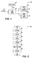
- X-ray system 100 includes a display device 110, an X-ray gantry 130 and a table 140, all connected to an X-ray control system 120.
- X-ray gantry 130 includes an X-ray generator 132; table 140 includes an X-ray sensor 142.
- X-ray gantry 130 includes both X-ray generator 132 and X-ray sensor 142 and moves generator 132 and sensor 142 relative to a location on table 140.
- X-ray control system 120 stores an X-ray exposure as an image along with the associated positions of X-ray gantry 130 and table 140.
- the X-ray images are displayed on display device 110 in various configurations. Typically, the last X-ray exposure taken is displayed on the display device 110.
- X-ray control system 120 includes one or more user inputs 122.
- User inputs 122 direct X-ray control system 120 under operator control of the movement of X-ray gantry 130, or table 140, or both, to a new position between X-ray exposures.
- display device 110 is placed near the operator and he or she uses a pointing device to select the position on display device 110 where he or she desires the next X-ray exposure to be centered.
- the pointing device may be, but is not limited to, a mouse, a trackball or a touch screen.
- X-ray control system 120 detects user input 122 and correlates user input 122 to a new X-ray exposure center position or reference point.
- X-ray control system 120 moves X-ray gantry 130 and/or table 140 to their required locations for a new X-ray exposure and takes a new X-ray exposure.
- the new X-ray exposure is then displayed as an image on display device 110.
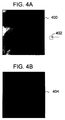
- FIG. 2 A block diagram shown in Figure 2 shows one embodiment 200 of the X-ray control method discussed above.
- system 100 displays an X-ray image on display device 110.
- an operator selects a position for taking a second X-ray image and at 230, system 100 shifts X-ray gantry 130 or table 140, or both, to the next position.
- system 100 requests an X-ray exposure to be taken from gantry 130.
- image processing is completed by the control system 120 and, at 260, an image representing the X-ray is displayed on display device 110. This process repeats as often as is necessary to provide the desired X-ray images.
- FIG. 3 Another embodiment 300 of the X-ray control method discussed above is shown in Figure 3.
- X-ray gantry and table positions are stored with data from the first exposure.
- X-ray gantry and table positions are stored automatically as part of capturing the first exposure.
- the operator enters X-ray gantry and table positions.
- control moves to 315, where an image representing capture of the first exposure is displayed for the operator.
- Control then moves to 320, where system 120 waits for input from the operator indicating a location to be used to position gantry 130 and/or table 140 for the next exposure.
- control moves to 325, where system 100 correlates the location selected to a new X-ray exposure position.
- the location selected on the display is treated as the center position for the next exposure. It should be noted, however, that the location selected does not have to be used as the center position for the next exposure. Instead, the location selected could be interpreted to correlate to other useful reference points for the X-ray fluoroscopy machinery.
- X-ray control system 120 moves the X-ray gantry 130 or table 140, or both, to new positions as a function of the selected location.
- control system 120 stores the new position of the gantry 130 and table 140.
- a new exposure is taken by X-ray control system 120.
- the new exposure is displayed on display device 110. Control then moves to 320, where X-ray control system 120 waits for operator entry of the next selected location.
- X-rays are turned off while system 100 moves to a new location. Since X-rays are not being generated while the X-ray gantry 130 and table 140 are in motion the radiation dosage is effectively reduced. In addition, the position of the X-ray gantry 130 and table 140 is more accurately determined by X-ray control system 120. This is in sharp contrast to traditional methods, which raise health and safety issues related to excess X-ray exposure. Traditional methods, where an operator manually moves the X-ray fluoroscopy machinery, use a high acquisition data rate for X-ray exposures. Because of the high acquisition data rate used with such traditional methods, both operators and patients receive a higher radiation dosage.
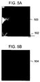
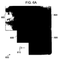
- FIGS 4a and 4b Images representative of successive X-ray image acquisitions are shown in Figures 4a and 4b, in Figures 5a and 5b and in Figures 6a-6c.
- the example shown in Figures 4a and 4b, in Figures 5a and 5b and in Figures 6a-6c use a rectangular bitmap of a heart taken at the Mayo Clinic using a touch screen display panel.
- a point 402 for a new X-ray exposure is selected by an operator touching outside a first image 400.
- Control system 120 then processes the selected location to determine a new position for either X-ray gantry 130 or table 140, or both, and an exposure is made.
- An image representing the resulting exposure is shown as image 404 in Figure 4b.
- a point 502 within an X-ray image 500 is selected by an operator.
- Control system 120 then takes a new X-ray exposure, shown as image 504 in Figure 5b, based on the point selected by the operator.
- X-ray control system 120 includes a zoom feature. Once an operator has processed two or more X-ray exposures, the operator can use the zoom out function to display a image that is a composite of the X-ray images received at that point.
- a composite image 600 is shown in Figure 6a.
- images 602, 604, 606 and 608 were taken in some order.
- the operator displays composite image 600 and uses that image to select the location 610 of the next exposure. If, as is shown in Figure 6a, a selection is made within the missing quadrant, x-ray gantry 130 and/or table 140 are moved to the appropriate locations. (In one embodiment, however, the location selected must be made in the center of the missing quadrant in order to generate an image covering the entirety of the missing quadrant.)
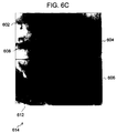
- location 610 Once location 610 is selected, an exposure is made and an image such as image 612 shown in Fig. 6b is generated.
- the operator can use the zoom-out feature to display a new composite image 614 which includes contributions from each of the images 602, 604, 606, 608 and 614. Overlapping areas are merged using standard image processing methods.
- X-ray fluoroscopy is not required while moving the X-ray gantry 130, or table 140, or both, because the spatial distances are determined by X-ray control system 120 based on the point selected by the operator. As a result, X-ray dosage for both operators and patients is greatly reduced.
- system 100 includes a system controller 710, input/output system 715, a positioner 720, an image processor 725, image acquisition system 730 and X-ray generation system 735.
- System controller 710 controls each of positioner 720, image processor 725, image acquisition system 730 and X-ray generation system 735 using control lines 702 and data lines 703.
- Image acquisition system 730 receives X-rays generated by X-ray generation system 735 and forwards data representative of the X-rays received to image processor 725.
- Image processor 725 includes a displays.
- Image processor 725 generates images based on the data received from image acquisition system 730 and displays the images on its display. An operator selects a location within the image shown on the display and the information regarding the selected location is transferred to system controller 710.
- System controller 710 processes the information received from the operator and instructs positioner 720 as to the desired positioning of the patient relative to the X-ray source.
- the patient is held stationary while the source and receptor move around the patient.
- the table moves relative to a stationary X-ray source.
- both the table holding the patient and the X-ray source move while positioning for the next exposure.
- input/output system 715 is used to connect to service tools, to external networks or to external monitors. Images captured within system controller 710 can be exported to system 715, where they can be transmitted across a network, read by a service tool or displayed on external display devices.
- X-ray system 100 includes system cabinet 902, external video capture and video display devices 904, service tool 906, external network interfaces 908, two X-ray sources 930 and 932, a display 934 and assorted data capture and patient positioning controls.
- images are examined in real-time for a change in state or movement of a relevant structure or flow (hereafter referred to as an object.)
- pattern recognition is used to examine the image for a change in state or movement of a relevant structure or flow.
- the information obtained from the image itself about the object is correlated to a position in the image and, in one such embodiment, in the patient.
- the change is tracked automatically by the X-ray control system.
- control logic is used to track the object and to change the relative position of the patient to the X-ray source to follow the object (for example, moving the table to keep the object centered).
- control logic can be used to change the size and dose of the X-ray (e.g., collimating to reduce the size of the image and therefore the dosage to the patient.)
- display methods are used to highlight the object and to distinguish it from the surrounding anatomy (e.g., using one color to denote a catheter tip and another to represent the vessel wall).
- Potential benefits of using automatic image data feedback and control as described above include faster procedures, less operator intervention during an X-ray procedure, and less dosage to the operators and patient.
- X-ray control system 120 automatically follows the tip of a catheter while a doctor inserts it into a leg during an embolization procedure.
- the catheter tip may be centered exactly in the image, or it may be positioned a certain distance from the edge of the image.
- image data feedback the number, size, and duration of the X-ray images is reduced.
- X-ray control system 120 automatically follows contrast injected into a body, while it flows through blood vessels in a major artery.
- the size of the image is maintained and, as a result, the radiation dosage to the patient is limited.
- the number and size of the images required is reduced by using information about the bolus location as input to X-ray control system 120.
- X-ray system 120 enhances anti-collision techniques in X-ray fluoroscopy by recognizing skin, organs, or bones in the X-ray image and using anatomical relationships to avoid collision. Such an approach permits maintaining a smaller distance between patient and the detector, especially during the automatic tracking described above.
- X-ray system 120 changes the color of a catheter tip during insertion so that an operator can locate it more easily.
- An advantage of X-ray system 100 is that an operator or control system can interactively select the position of the next X-ray exposure based on image information contained in previous X-ray exposures.
- the present X-ray control system more accurately determines the locations of an X-ray, which results in less radiation dosage.
- the use of X-ray fluoroscopy is completely eliminated.
- accurate X-ray exposure locations provide an opportunity to decrease the field of view (FOV), which further reduces X-ray exposure and at the same time increases image quality.
- FOV field of view
- X-ray system 100 therefore provides several overall benefits. There is a reduction in the total radiation dosage to operators and patients when less X-ray fluoroscopy is used. The accurate location of the next X-ray exposure results in faster X-ray medical procedures and also reduces the total radiation dosage to patients and operators. Finally, by using smaller FOV's with X-ray medical procedures, X-ray system 100 increases image quality while decreasing radiation dosage.
Landscapes
- Health & Medical Sciences (AREA)
- Life Sciences & Earth Sciences (AREA)
- Engineering & Computer Science (AREA)
- Medical Informatics (AREA)
- Radiology & Medical Imaging (AREA)
- Molecular Biology (AREA)
- Biophysics (AREA)
- Nuclear Medicine, Radiotherapy & Molecular Imaging (AREA)
- Optics & Photonics (AREA)
- Pathology (AREA)
- Physics & Mathematics (AREA)
- Biomedical Technology (AREA)
- Heart & Thoracic Surgery (AREA)
- High Energy & Nuclear Physics (AREA)
- Surgery (AREA)
- Animal Behavior & Ethology (AREA)
- General Health & Medical Sciences (AREA)
- Public Health (AREA)
- Veterinary Medicine (AREA)
- Human Computer Interaction (AREA)
- Apparatus For Radiation Diagnosis (AREA)
Abstract
Description
- The present invention is related to medical imaging, and more particularly to a system and method for positioning an acquisition device and acquiring an image based on image data.
- Currently medical X-ray procedures, such as X-ray fluoroscopy, use a high acquisition data rate for X-ray images. The images generated by the X-ray fluoroscopy are then used to manually guide a tool through the internal structure of an opaque body or object (e.g. the human body). Directing this tool, which may be a medical device such as a catheter, through an opaque object is usually quite inefficient and inaccurate since it relies on the operator of the X-ray fluoroscopy device and the X-ray machinery to manually estimate the next position using various types of control techniques developed for this purpose. X-ray fluoroscopy is used for interventional medical procedures such as balloon angioplasty and neuroembolizations. These medical procedures have been extremely successful and widely utilized. Their wide utilization has resulted in X-ray fluoroscopy accounting for over one-half of the diagnostic X-ray dosage. Such wide spread use has, however resulted in documented instances of severe skin injury.
- One way to reduce radiation exposure of patients and operators would be to optimize the X-ray image acquisition and filtering techniques used for X-ray fluoroscopy. One such approach uses a combination of lowering the acquisition data rate of the X-ray fluoroscopy and increasing the X-ray image resolution to direct the X-ray fluoroscopy machinery. However, this approach relies on the human operator to manually control the X-ray machinery, which introduces uncertainty.
- To-date, there have not been any solutions addressing the uncertainty introduced by an operator manually controlling the X-ray fluoroscopy machinery. Instead, solutions explored in the medical industry have been limited to increasing the efficiency of the X-ray fluoroscopy machinery by increasing the image resolution, or to reducing the radiation exposure for the operator and patient by decreasing the number of noisy images produced by the X-ray fluoroscopy machinery.
- What is needed is an X-ray control system, device and method for interactively processing a selection point for an X-ray exposure based on a previous X-ray exposure to improve the productivity and safety of medical X-ray procedures.
- According to one aspect of the present invention, an X-ray system and method is described for use in a medical application to supplement or replace fluoroscopy. The X-ray system includes a display device, a gantry having an X-ray generator, a table having an X-ray sensor, and an X-ray control system connected to the display device, the gantry and the table. The X-ray control system includes user input for indicating the position of the next X-ray exposure. The X-ray control system receives X-ray data from the sensor, processes the data to form an X-ray image, displays the X-ray image on the display device and shifts the X-ray generator relative to the X-ray sensor. The amount and direction of shift is accurately determined using data from the previous X-ray image.
- According to another aspect of the present invention, a system and method of positioning an X-ray generator relative to the X-ray sensor is described. X-ray data is received from the sensor and processed to form an X-ray image. The X-ray image is displayed on a display device and a position is selected on the X-ray image. The X-ray generator is shifted relative to the X-ray sensor as a function of the position selected on the X-ray image.
- According to yet another aspect of the present invention, a system and method for tracking a first object within a second object is described. X-rays are projected through the second object in the vicinity of the first object, captured and used to generate a display image. The display image is displayed. The appearance of the first object is emphasized within the second object, movement of the first object within the second object is detected and relative position of the second object to the X-ray source is changed as a function of movement of the first object before a new display image is captured.
- The X-ray control system, device and method utilizes a computing system to determine the next position of the X-ray fluoroscopy machinery based on the information processed from the previous X-ray image, thus decreasing the uncertainty introduced by a operator manually controlling the X-ray fluoroscopy machinery. The location of the next exposure is also more accurate since it is controlled by an X-ray control system. Such an approach contrasts with current X-ray fluoroscopy techniques that rely upon an operator to guide the X-ray fluoroscopy machinery manually. Accurately directing the X-ray fluoroscopy machinery also reduces the radiation exposure for both operators and the patients.
- The invention will now be described in greater detail, by way of example, with reference to the drawings, in which:
- Figure 1 illustrates one embodiment of an X-ray control system;
- Figure 2 shows one embodiment of a block diagram for an X-ray control system shown in Figure 1;
- Figure 3 is one embodiment of a block diagram of an X-ray control system according to Figure 2;
- Figures 4a and 4b illustrate one embodiment of a selection process for selecting a new X-ray exposure;
- Figures 5a and 5b illustrate another embodiment of a selection process for selecting a new X-ray exposure;
- Figures 6a, 6b, and 6c illustrate a zoom feature;
- Figure 7 is an alternate embodiment of the block diagram of Figure 2;
- Figure 8 shows a detailed block diagram of an X-ray system according to the block diagram of Figure 7.
-
- Portions of the detailed descriptions that follow are presented in terms of algorithms and symbolic representations of operations on data bits within a computer memory. These algorithmic descriptions and representations are the means used by those skilled in the data processing arts to most effectively convey the substance of their work to others skilled in the art. Each algorithm is a self-consistent sequence of steps leading to a desired result. The steps include those requiring physical manipulations of physical quantities. Usually, though not necessarily, these quantities take the form of electrical or magnetic signals capable of being stored, transferred, combined, compared, and otherwise manipulated. It has proven convenient at times, principally for reasons of common usage, to refer to these signals as bits, values, elements, symbols, characters, terms, numbers, or the like. It should be borne in mind, however, that all of these and similar terms are to be associated with the appropriate physical quantities and are merely convenient labels applied to these quantities. Unless specifically stated otherwise as apparent from the following discussions, it is appreciated that throughout the present invention, discussions utilizing terms such as "processing" or "computing" or "calculating" or "determining" or "displaying" or the like, refer to the action and processes of a computer system, or similar electronic computing device, that manipulates and transforms data represented as physical (electronic) quantities within the computer system's registers and memories into other data similarly represented as physical quantities within the computer system memories or registers or other such information storage, transmission or display devices.
- An
X-ray system 100 is shown in Figure 1.X-ray system 100 includes adisplay device 110, anX-ray gantry 130 and a table 140, all connected to anX-ray control system 120. In one embodiment, such as is shown in Fig. 1,X-ray gantry 130 includes anX-ray generator 132; table 140 includes anX-ray sensor 142. In another embodiment,X-ray gantry 130 includes bothX-ray generator 132 andX-ray sensor 142 and movesgenerator 132 andsensor 142 relative to a location on table 140. -
X-ray control system 120 stores an X-ray exposure as an image along with the associated positions ofX-ray gantry 130 and table 140. The X-ray images are displayed ondisplay device 110 in various configurations. Typically, the last X-ray exposure taken is displayed on thedisplay device 110. - In one embodiment,
X-ray control system 120 includes one ormore user inputs 122.User inputs 122 directX-ray control system 120 under operator control of the movement ofX-ray gantry 130, or table 140, or both, to a new position between X-ray exposures. In one such embodiment,display device 110 is placed near the operator and he or she uses a pointing device to select the position ondisplay device 110 where he or she desires the next X-ray exposure to be centered. The pointing device may be, but is not limited to, a mouse, a trackball or a touch screen.X-ray control system 120 detectsuser input 122 and correlatesuser input 122 to a new X-ray exposure center position or reference point. After a new center position or reference point is determined,X-ray control system 120 movesX-ray gantry 130 and/or table 140 to their required locations for a new X-ray exposure and takes a new X-ray exposure. The new X-ray exposure is then displayed as an image ondisplay device 110. - A block diagram shown in Figure 2 shows one
embodiment 200 of the X-ray control method discussed above. At 210,system 100 displays an X-ray image ondisplay device 110. At 220, an operator selects a position for taking a second X-ray image and at 230,system 100shifts X-ray gantry 130 or table 140, or both, to the next position. When the shifting is complete, at 240system 100 requests an X-ray exposure to be taken fromgantry 130. At 250, image processing is completed by thecontrol system 120 and, at 260, an image representing the X-ray is displayed ondisplay device 110. This process repeats as often as is necessary to provide the desired X-ray images. - Another
embodiment 300 of the X-ray control method discussed above is shown in Figure 3. At 310, X-ray gantry and table positions are stored with data from the first exposure. In one such embodiment, X-ray gantry and table positions are stored automatically as part of capturing the first exposure. In another such embodiment, the operator enters X-ray gantry and table positions. - At 315, control moves to 315, where an image representing capture of the first exposure is displayed for the operator. Control then moves to 320, where
system 120 waits for input from the operator indicating a location to be used to positiongantry 130 and/or table 140 for the next exposure. Once received, control moves to 325, wheresystem 100 correlates the location selected to a new X-ray exposure position. In one embodiment, the location selected on the display is treated as the center position for the next exposure. It should be noted, however, that the location selected does not have to be used as the center position for the next exposure. Instead, the location selected could be interpreted to correlate to other useful reference points for the X-ray fluoroscopy machinery. - At 330,
X-ray control system 120 moves theX-ray gantry 130 or table 140, or both, to new positions as a function of the selected location. At 335,control system 120 stores the new position of thegantry 130 and table 140. At 340, a new exposure is taken byX-ray control system 120. At 345, the new exposure is displayed ondisplay device 110. Control then moves to 320, whereX-ray control system 120 waits for operator entry of the next selected location. - In one embodiment, X-rays are turned off while
system 100 moves to a new location. Since X-rays are not being generated while theX-ray gantry 130 and table 140 are in motion the radiation dosage is effectively reduced. In addition, the position of theX-ray gantry 130 and table 140 is more accurately determined byX-ray control system 120. This is in sharp contrast to traditional methods, which raise health and safety issues related to excess X-ray exposure. Traditional methods, where an operator manually moves the X-ray fluoroscopy machinery, use a high acquisition data rate for X-ray exposures. Because of the high acquisition data rate used with such traditional methods, both operators and patients receive a higher radiation dosage. - Images representative of successive X-ray image acquisitions are shown in Figures 4a and 4b, in Figures 5a and 5b and in Figures 6a-6c. The example shown in Figures 4a and 4b, in Figures 5a and 5b and in Figures 6a-6c use a rectangular bitmap of a heart taken at the Mayo Clinic using a touch screen display panel. In the embodiment shown in Figures 4a-b, a
point 402 for a new X-ray exposure is selected by an operator touching outside afirst image 400.Control system 120 then processes the selected location to determine a new position for eitherX-ray gantry 130 or table 140, or both, and an exposure is made. An image representing the resulting exposure is shown asimage 404 in Figure 4b. - In the example shown in Figures 5a and 5b, a
point 502 within anX-ray image 500 is selected by an operator.Control system 120 then takes a new X-ray exposure, shown asimage 504 in Figure 5b, based on the point selected by the operator. - In one embodiment,
X-ray control system 120 includes a zoom feature. Once an operator has processed two or more X-ray exposures, the operator can use the zoom out function to display a image that is a composite of the X-ray images received at that point. One example of such acomposite image 600 is shown in Figure 6a. In thecomposite image 600 shown in Figure 6a,images composite image 600 and uses that image to select thelocation 610 of the next exposure. If, as is shown in Figure 6a, a selection is made within the missing quadrant,x-ray gantry 130 and/or table 140 are moved to the appropriate locations. (In one embodiment, however, the location selected must be made in the center of the missing quadrant in order to generate an image covering the entirety of the missing quadrant.) - Once
location 610 is selected, an exposure is made and an image such asimage 612 shown in Fig. 6b is generated. The operator can use the zoom-out feature to display a newcomposite image 614 which includes contributions from each of theimages - In the examples shown in Figures 4a-b, 5a-b, and 6a-c, X-ray fluoroscopy is not required while moving the
X-ray gantry 130, or table 140, or both, because the spatial distances are determined byX-ray control system 120 based on the point selected by the operator. As a result, X-ray dosage for both operators and patients is greatly reduced. - The block diagram shown in Figure 7 illustrates another embodiment of
X-ray system 100. Each of the blocks forsystem 100 performs one or more activities as indicated bykey 705. In the embodiment shown in Figure 7,system 100 includes asystem controller 710, input/output system 715, apositioner 720, animage processor 725,image acquisition system 730 andX-ray generation system 735.System controller 710 controls each ofpositioner 720,image processor 725,image acquisition system 730 andX-ray generation system 735 usingcontrol lines 702 and data lines 703.Image acquisition system 730 receives X-rays generated byX-ray generation system 735 and forwards data representative of the X-rays received to imageprocessor 725.Image processor 725 includes a displays.Image processor 725 generates images based on the data received fromimage acquisition system 730 and displays the images on its display. An operator selects a location within the image shown on the display and the information regarding the selected location is transferred tosystem controller 710.System controller 710 processes the information received from the operator and instructspositioner 720 as to the desired positioning of the patient relative to the X-ray source. In one such embodiment, the patient is held stationary while the source and receptor move around the patient. In another embodiment, the table moves relative to a stationary X-ray source. In yet another embodiment, both the table holding the patient and the X-ray source move while positioning for the next exposure. - In the embodiment shown in Figure 7, input/
output system 715 is used to connect to service tools, to external networks or to external monitors. Images captured withinsystem controller 710 can be exported tosystem 715, where they can be transmitted across a network, read by a service tool or displayed on external display devices. - A detailed block diagram of another embodiment of
X-ray system 100 is illustrated in Figure 8. In one embodiment,X-ray system 100 includessystem cabinet 902, external video capture andvideo display devices 904,service tool 906, external network interfaces 908, twoX-ray sources display 934 and assorted data capture and patient positioning controls. - In one embodiment, images are examined in real-time for a change in state or movement of a relevant structure or flow (hereafter referred to as an object.) In one embodiment pattern recognition is used to examine the image for a change in state or movement of a relevant structure or flow. The information obtained from the image itself about the object is correlated to a position in the image and, in one such embodiment, in the patient. When the object changes relative position in the image, the change is tracked automatically by the X-ray control system.
- In one such embodiment, control logic is used to track the object and to change the relative position of the patient to the X-ray source to follow the object (for example, moving the table to keep the object centered). In addition, control logic can be used to change the size and dose of the X-ray (e.g., collimating to reduce the size of the image and therefore the dosage to the patient.)
- In one such embodiment, display methods are used to highlight the object and to distinguish it from the surrounding anatomy (e.g., using one color to denote a catheter tip and another to represent the vessel wall).
- The military and the transportation industry have been creating new technologies related to identifying objects both moving and static in digital images. Such enhancements have even made their way into the mass media where real-time fast moving objects (i.e. a hockey puck) are tracked and enhanced with color so that viewers can follow the object more closely. In the medical industry, Computer Aided Detection has been demonstrated for locating potential breast tumors ― although such detection is done off-line rather than in real-time. Since X-ray images are now being created in high-resolution digital format, there is an opportunity to use information contained in the digital image as input to the X-ray control system and allow change in its operational behavior.
- Potential benefits of using automatic image data feedback and control as described above include faster procedures, less operator intervention during an X-ray procedure, and less dosage to the operators and patient.
- In one embodIment,
X-ray control system 120 automatically follows the tip of a catheter while a doctor inserts it into a leg during an embolization procedure. The catheter tip may be centered exactly in the image, or it may be positioned a certain distance from the edge of the image. By using image data feedback, the number, size, and duration of the X-ray images is reduced. - In a second embodiment,
X-ray control system 120 automatically follows contrast injected into a body, while it flows through blood vessels in a major artery. In one such embodiment, the size of the image is maintained and, as a result, the radiation dosage to the patient is limited. In one such embodiment, the number and size of the images required is reduced by using information about the bolus location as input toX-ray control system 120. - In a third embodiment,
X-ray system 120 enhances anti-collision techniques in X-ray fluoroscopy by recognizing skin, organs, or bones in the X-ray image and using anatomical relationships to avoid collision. Such an approach permits maintaining a smaller distance between patient and the detector, especially during the automatic tracking described above. - In a fourth embodiment,
X-ray system 120 changes the color of a catheter tip during insertion so that an operator can locate it more easily. - An advantage of
X-ray system 100 is that an operator or control system can interactively select the position of the next X-ray exposure based on image information contained in previous X-ray exposures. In addition, the present X-ray control system more accurately determines the locations of an X-ray, which results in less radiation dosage. In one embodiment, the use of X-ray fluoroscopy is completely eliminated. Furthermore, accurate X-ray exposure locations provide an opportunity to decrease the field of view (FOV), which further reduces X-ray exposure and at the same time increases image quality. -
X-ray system 100 therefore provides several overall benefits. There is a reduction in the total radiation dosage to operators and patients when less X-ray fluoroscopy is used. The accurate location of the next X-ray exposure results in faster X-ray medical procedures and also reduces the total radiation dosage to patients and operators. Finally, by using smaller FOV's with X-ray medical procedures,X-ray system 100 increases image quality while decreasing radiation dosage. - For the sake of good order, various features of the invention are set out in the following clauses:-
- 1. In an X-ray system having an X-ray generator and an X-ray sensor, a method
of positioning the X-ray generator relative to the X-ray sensor, comprising:
- displaying a display image, wherein the display image includes data representing an X-ray image; selecting a position on the display image; and
- shifting the X-ray generator relative to the X-ray sensor as a function of the position selected on the display image.
- 2. The method of clause 1, wherein selecting a position on the display image includes pointing at the image with a pointing device.
- 3. The method of clause 1, wherein selecting a position on the display image includes touching the image.
- 4. The method of clause 1, wherein selecting a position on the display image includes tracking movement of a first object in the image relative to a second object in the image, wherein the control logic chooses the position selected on the image as a function of movement of the first object relative to the second object.
- 5. A computer readable medium comprising program code for executing the method of clause 1.
- 6. An X-ray system, comprising:
- a display device; a gantry having an X-ray generator;
- a table having an X-ray sensor; and
- an X-ray control system connected to the display device, the gantry and the table, wherein the X-ray control system receives X-ray data front the sensor, processes the data to form an X-ray image, displays the X-ray image on the display device and shifts the X-ray generator relative to the X-ray sensor as a function of a position selected on the X-ray image.
- 7. The X-ray system according to clause 6, wherein the display device includes a touch screen and wherein a user indicates the position selected on the X-ray image by touching the image on the touch screen.
- 8. The X-ray system according to clause 6, wherein the control system includes a pointing device capable of displaying a pointer icon on the display device and wherein a user indicates the position selected on the X-ray image by pointing to the image with the pointing device.
- 9. The X-ray system according to clause 6, wherein the control system includes control logic for tracking movement of a first object in the X-ray image relative to a second object in the X-ray image, wherein the control logic selects the position selected on the X-ray image as a function of movement of the first object relative to the second object.
- 10. In an X-ray system having an X-ray generator, an X-ray sensor and a display
device, a method of positioning the X-ray generator relative to the X-ray sensor,
comprising:
- receiving X-ray data from the sensor; processing the X-ray data to form an X-ray image;
- displaying the X-ray image on the display device; selecting a position on the X-ray image; and
- shifting the X-ray generator relative to the X-ray sensor as a function of the position selected on the X-ray image.
- 11. The method of clause 10, wherein selecting a position on the X-ray image includes pointing at the image with a pointing device.
- 12. The method of clause 10, wherein selecting a position on the X-ray image includes touching the image.
- 13. The method of clause 10, wherein selecting a position on the X-ray image includes tracking movement of a first object in the image relative to a second object in the image, wherein the control logic selects the position as a function of movement of the first object relative to the second object.
- 14. A computer readable medium comprising program code for executing the method of clause 10.
- 15. In an X-ray system having an X-ray generator and an X-ray sensor, a method
of tracking a first object within a second object, comprising: projecting X-rays
through the second object in the vicinity of the first object; capturing X-rays passing
through the second object;
- generating a display image as a function of the captured X-rays; displaying the display image;
- emphasizing the first object within the second object; changing relative position of the second object to the X-ray source as a function of movement of the first object; and
- capturing a new display image.
- 16. The method of clause 15, wherein the display image is in color and wherein emphasizing includes changing the color of the first object.
- 17. The method of clause 15, wherein the display image is in color and wherein emphasizing includes changing the color of objects close to the first object.
- 18. The method of clause 15, wherein emphasizing includes performing pattern recognition on the display image to detect the first object.
- 19. The method of clause 15, wherein capturing a new display image includes reducing image size through collimating.
- 20. The method of clause 15, wherein the first object is a catheter tip inserted into a patient during an embolization procedure.
- 21. The method of clause 15, wherein the first object is contrast injected into a blood vessel.
- 22. The method of clause 15, wherein the second object is a body and the first object is an object inserted into the body, wherein the display image is in color and wherein emphasizing includes changing the color of body structures close to the first object.
- 23. A computer readable medium comprising program code for executing the method of clause 15.
- 24. An image processing system for controlling movement of an electromagnetic
signal source relative to an body, wherein the electromagnetic signal source generates
an electromagnetic signal, the system comprising:
- a signal processor, wherein the signal processor receives data representing an interaction between the electromagnetic signal and the body and processes the data to form an image; and
- a control system, wherein the control system includes: selection means for selecting a point on the image; and
- positioning means for shifting the electromagnetic source relative to the body as a function of the point selected.
- 25. The image processing system according to clause 24, wherein the selection means includes a touch screen and wherein a user indicates the point selected by touching the image displayed on the touch screen.
- 26. The image processing system according to clause 24, wherein the selection means includes a pointing device capable of displaying a pointer icon on a display device and wherein a user indicates the point selected on the image by pointing to the image with the pointing device.
- 27. The image processing system according to clause 24, wherein the selection means includes control logic for tracking movement of a first object in the image relative to a second object in the image and selection logic for selecting the point selected as a function of movement of the first object relative to the second object.
- 28. The image processing system according to clause 24, wherein the signal processor includes means for emphasizing objects within the body.
-
Claims (10)
- A method of positioning the X-ray generator relative to the X-ray sensor in an X-ray system, comprising:displaying a display image, wherein the display image includes data representing an X-ray image; selecting a position on the display image; andshifting the X-ray generator relative to the X-ray sensor as a function of the position selected on the display image.
- The method of claim 1, wherein selecting a position on the display image includes pointing at the image with a pointing device.
- An X-ray system, comprising:a display device; a gantry having an X-ray generator;a table having an X-ray sensor; andan X-ray control system connected to the display device, the gantry and the table, wherein the X-ray control system receives X-ray data front the sensor, processes the data to form an X-ray image, displays the X-ray image on the display device and shifts the X-ray generator relative to the X-ray sensor as a function of a position selected on the X-ray image.
- The X-ray system according to claim 3, wherein the display device includes a touch screen and wherein a user indicates the position selected on the X-ray image by touching the image on the touch screen.
- A method of positioning the X-ray generator relative to the X-ray sensor in an X-ray system having an X-ray generator, an X-ray sensor and a display device, comprising:receiving X-ray data from the sensor; processing the X-ray data to form an X-ray image;displaying the X-ray image on the display device; selecting a position on the X-ray image; andshifting the X-ray generator relative to the X-ray sensor as a function of the position selected on the X-ray image.
- The method of claim 10, wherein selecting a position on the X-ray image includes pointing at the image with a pointing device.
- A method of tracking a first object within a second object In an X-ray system having an X-ray generator and an X-ray sensor, comprising:projecting X-rays through the second object in the vicinity of the first object;capturing X-rays passing through the second object;generating a display image as a function of the captured X-rays;displaying the display image;emphasizing the first object within the second object;changing relative position of the second object to the X-ray source as a function of movement of the first object; andcapturing a new display image.
- The method of claim 7, wherein the display image is in color and wherein emphasizing includes changing the color of the first object.
- A computer readable medium comprising program code for executing the method of any one of claims 2, 5, 6, 7 or 8.
- An image processing system for controlling movement of an electromagnetic signal source relative to an body, wherein the electromagnetic signal source generates an electromagnetic signal, the system comprising:a signal processor, wherein the signal processor receives data representing an interaction between the electromagnetic signal and the body and processes the data to form an image; anda control system, wherein the control system includes:selection means for selecting a point on the image; andpositioning means for shifting the electromagnetic source relative to the body as a function of the point selected.
Applications Claiming Priority (2)
| Application Number | Priority Date | Filing Date | Title |
|---|---|---|---|
| US418167 | 1999-10-13 | ||
| US09/418,167 US6463121B1 (en) | 1999-10-13 | 1999-10-13 | Interactive x-ray position and exposure control using image data as reference information |
Publications (2)
| Publication Number | Publication Date |
|---|---|
| EP1092391A1 true EP1092391A1 (en) | 2001-04-18 |
| EP1092391B1 EP1092391B1 (en) | 2007-05-09 |
Family
ID=23657000
Family Applications (1)
| Application Number | Title | Priority Date | Filing Date |
|---|---|---|---|
| EP00308929A Expired - Lifetime EP1092391B1 (en) | 1999-10-13 | 2000-10-11 | Interactive X-ray position and exposure control using image data as reference information |
Country Status (4)
| Country | Link |
|---|---|
| US (1) | US6463121B1 (en) |
| EP (1) | EP1092391B1 (en) |
| JP (1) | JP4590084B2 (en) |
| DE (1) | DE60034749T2 (en) |
Cited By (7)
| Publication number | Priority date | Publication date | Assignee | Title |
|---|---|---|---|---|
| WO2004008970A1 (en) * | 2002-07-20 | 2004-01-29 | The University Of Surrey | Image colouring |
| EP1484016A1 (en) | 2003-06-03 | 2004-12-08 | GE Medical Systems Global Technology Company LLC | Method and apparatus for acquisition of a composite image with a digital detector |
| US6944265B2 (en) | 2002-11-25 | 2005-09-13 | Ge Medical Systems Global Technology Company, Llc | Image pasting using geometry measurement and a flat-panel detector |
| EP1656550A4 (en) * | 2003-08-20 | 2007-04-18 | Varian Med Sys Inc | X-ray imaging system with automatic image resolution enhancement |
| WO2007031945A3 (en) * | 2005-09-14 | 2007-10-18 | Koninkl Philips Electronics Nv | Low-dose iso-centering |
| WO2015076739A1 (en) * | 2013-11-19 | 2015-05-28 | Scanflex Healthcare AB | Flat panel x-ray imaging device - twin dual control gui |
| US9480440B2 (en) | 2011-09-28 | 2016-11-01 | Qr Srl | System and method for cone beam computed tomography |
Families Citing this family (93)
| Publication number | Priority date | Publication date | Assignee | Title |
|---|---|---|---|---|
| US6568851B2 (en) * | 2000-10-25 | 2003-05-27 | Kabushiki Kaisha Toshiba | X-ray CT scanner |
| JP3926120B2 (en) * | 2001-02-16 | 2007-06-06 | 株式会社モリタ製作所 | X-ray imaging position setting means for an object, and X-ray imaging apparatus provided with this means |
| DE10108298A1 (en) * | 2001-02-21 | 2002-09-26 | Sirona Dental Systems Gmbh | Arrangement and method for positioning a digital X-ray device |
| DE10109754B4 (en) * | 2001-02-28 | 2004-12-09 | Siemens Ag | Universal x-ray machine |
| DE60215932T2 (en) * | 2001-04-03 | 2007-09-13 | L-3 Communications Security & Detection Systems, Woburn | X INVESTIGATION SYSTEM |
| US6907103B2 (en) * | 2002-06-19 | 2005-06-14 | Agilent Technologies, Inc. | Capturing images of moving objects with a moving illumination point source |
| US6925149B2 (en) * | 2002-07-30 | 2005-08-02 | Siemens Medical Solutions Usa, Inc. | Radiation imaging system |
| US6922462B2 (en) * | 2002-07-31 | 2005-07-26 | Ge Medical Systems Global Technology Company, Llc | Method, system and computer product for plaque characterization |
| US7133492B2 (en) * | 2004-03-30 | 2006-11-07 | Siemens Medical Solutions Usa, Inc. | Method for reducing radiation exposure during patient positioning |
| US20060241370A1 (en) * | 2005-03-30 | 2006-10-26 | George Kramp | Medical x-ray imaging workflow improvement |
| JP3912606B2 (en) * | 2004-10-26 | 2007-05-09 | 株式会社リガク | X-ray thin film inspection apparatus, thin film inspection apparatus for product wafer and method thereof |
| DE102004059663A1 (en) * | 2004-12-10 | 2006-06-29 | Siemens Ag | Method for multidimensional imaging involves multi-row computer tomographs for scanning patient whereby scan speed is adjusted according to the propagation speed of contrast agent in scanning direction |
| US20070036266A1 (en) * | 2005-03-29 | 2007-02-15 | George Kramp | Medical x-ray imaging workflow improvement |
| US7209577B2 (en) | 2005-07-14 | 2007-04-24 | Logitech Europe S.A. | Facial feature-localized and global real-time video morphing |
| US7639782B2 (en) * | 2005-08-23 | 2009-12-29 | Ge Medical Systems Israel, Ltd. | Methods and systems for automatic patient table positioning |
| US8784336B2 (en) | 2005-08-24 | 2014-07-22 | C. R. Bard, Inc. | Stylet apparatuses and methods of manufacture |
| JP4810182B2 (en) * | 2005-10-17 | 2011-11-09 | キヤノン株式会社 | Radiography equipment |
| US7794407B2 (en) | 2006-10-23 | 2010-09-14 | Bard Access Systems, Inc. | Method of locating the tip of a central venous catheter |
| US8388546B2 (en) | 2006-10-23 | 2013-03-05 | Bard Access Systems, Inc. | Method of locating the tip of a central venous catheter |
| US7529336B2 (en) | 2007-05-31 | 2009-05-05 | Test Research, Inc. | System and method for laminography inspection |
| JP5464799B2 (en) * | 2007-11-16 | 2014-04-09 | キヤノン株式会社 | Image processing apparatus, image processing method, and program |
| US10449330B2 (en) | 2007-11-26 | 2019-10-22 | C. R. Bard, Inc. | Magnetic element-equipped needle assemblies |
| US10524691B2 (en) | 2007-11-26 | 2020-01-07 | C. R. Bard, Inc. | Needle assembly including an aligned magnetic element |
| EP2992825B1 (en) | 2007-11-26 | 2017-11-01 | C.R. Bard Inc. | Integrated system for intravascular placement of a catheter |
| US10751509B2 (en) | 2007-11-26 | 2020-08-25 | C. R. Bard, Inc. | Iconic representations for guidance of an indwelling medical device |
| US9521961B2 (en) | 2007-11-26 | 2016-12-20 | C. R. Bard, Inc. | Systems and methods for guiding a medical instrument |
| US9649048B2 (en) | 2007-11-26 | 2017-05-16 | C. R. Bard, Inc. | Systems and methods for breaching a sterile field for intravascular placement of a catheter |
| US8849382B2 (en) | 2007-11-26 | 2014-09-30 | C. R. Bard, Inc. | Apparatus and display methods relating to intravascular placement of a catheter |
| US8781555B2 (en) | 2007-11-26 | 2014-07-15 | C. R. Bard, Inc. | System for placement of a catheter including a signal-generating stylet |
| JP5550209B2 (en) * | 2007-12-25 | 2014-07-16 | キヤノン株式会社 | X-ray equipment |
| US8478382B2 (en) | 2008-02-11 | 2013-07-02 | C. R. Bard, Inc. | Systems and methods for positioning a catheter |
| JP5305747B2 (en) * | 2008-06-17 | 2013-10-02 | キヤノン株式会社 | Radiation image capturing apparatus, driving method thereof, and program |
| US8175684B2 (en) * | 2008-07-29 | 2012-05-08 | General Electric Company | Method for processing images and associated medical imaging system |
| US9901714B2 (en) | 2008-08-22 | 2018-02-27 | C. R. Bard, Inc. | Catheter assembly including ECG sensor and magnetic assemblies |
| JP4693884B2 (en) * | 2008-09-18 | 2011-06-01 | キヤノン株式会社 | Multi X-ray imaging apparatus and control method thereof |
| US8437833B2 (en) | 2008-10-07 | 2013-05-07 | Bard Access Systems, Inc. | Percutaneous magnetic gastrostomy |
| JP5313617B2 (en) * | 2008-10-15 | 2013-10-09 | 富士フイルム株式会社 | Radiation image detection device |
| JP2010213798A (en) * | 2009-03-13 | 2010-09-30 | Toshiba Corp | Cardiovascular x-ray diagnostic system |
| US9532724B2 (en) | 2009-06-12 | 2017-01-03 | Bard Access Systems, Inc. | Apparatus and method for catheter navigation using endovascular energy mapping |
| RU2691318C2 (en) | 2009-06-12 | 2019-06-11 | Бард Аксесс Системс, Инк. | Method for positioning catheter end |
| US7934869B2 (en) * | 2009-06-30 | 2011-05-03 | Mitsubishi Electric Research Labs, Inc. | Positioning an object based on aligned images of the object |
| EP2464407A4 (en) | 2009-08-10 | 2014-04-02 | Bard Access Systems Inc | DEVICES AND METHODS FOR ENDOVASCULAR ELECTROGRAPHY |
| CN102665541B (en) | 2009-09-29 | 2016-01-13 | C·R·巴德股份有限公司 | The probe used together with the equipment that the Ink vessel transfusing for conduit is placed |
| WO2011044421A1 (en) | 2009-10-08 | 2011-04-14 | C. R. Bard, Inc. | Spacers for use with an ultrasound probe |
| BR112012019354B1 (en) | 2010-02-02 | 2021-09-08 | C.R.Bard, Inc | METHOD FOR LOCATION OF AN IMPLANTABLE MEDICAL DEVICE |
| US10524741B2 (en) | 2010-03-31 | 2020-01-07 | Koninklijke Philips N.V. | Automated identification of an anatomy part |
| WO2011150376A1 (en) | 2010-05-28 | 2011-12-01 | C.R. Bard, Inc. | Apparatus for use with needle insertion guidance system |
| EP4122385A1 (en) | 2010-05-28 | 2023-01-25 | C. R. Bard, Inc. | Insertion guidance system for needles and medical components |
| CN103228219B (en) | 2010-08-09 | 2016-04-27 | C·R·巴德股份有限公司 | Support and Covering Structures for Ultrasound Probe Heads |
| JP5845260B2 (en) | 2010-08-20 | 2016-01-20 | シー・アール・バード・インコーポレーテッドC R Bard Incorporated | Reconfirmation of ECG support catheter tip placement |
| US9785246B2 (en) | 2010-10-06 | 2017-10-10 | Nuvasive, Inc. | Imaging system and method for use in surgical and interventional medical procedures |
| US11231787B2 (en) | 2010-10-06 | 2022-01-25 | Nuvasive, Inc. | Imaging system and method for use in surgical and interventional medical procedures |
| US8526700B2 (en) | 2010-10-06 | 2013-09-03 | Robert E. Isaacs | Imaging system and method for surgical and interventional medical procedures |
| WO2012058461A1 (en) | 2010-10-29 | 2012-05-03 | C.R.Bard, Inc. | Bioimpedance-assisted placement of a medical device |
| US20120155609A1 (en) * | 2010-12-20 | 2012-06-21 | General Electric Company | System and method of low dose exposure aided positioning (leap) for digital radiography |
| JP5579636B2 (en) * | 2011-02-07 | 2014-08-27 | 富士フイルム株式会社 | Radiographic imaging apparatus and radiographic imaging method |
| WO2012129374A1 (en) * | 2011-03-22 | 2012-09-27 | Corindus, Inc. | Robotic catheter system including imaging system control |
| JP6008960B2 (en) | 2011-07-06 | 2016-10-19 | シー・アール・バード・インコーポレーテッドC R Bard Incorporated | Needle length determination and calibration for insertion guidance systems |
| USD724745S1 (en) | 2011-08-09 | 2015-03-17 | C. R. Bard, Inc. | Cap for an ultrasound probe |
| USD699359S1 (en) | 2011-08-09 | 2014-02-11 | C. R. Bard, Inc. | Ultrasound probe head |
| US9211107B2 (en) | 2011-11-07 | 2015-12-15 | C. R. Bard, Inc. | Ruggedized ultrasound hydrogel insert |
| DE102012005899A1 (en) * | 2012-03-15 | 2013-09-19 | Fraunhofer-Gesellschaft zur Förderung der angewandten Forschung e.V. | Detector arrangement for taking X-ray images of an object to be imaged |
| JP6112773B2 (en) * | 2012-04-17 | 2017-04-12 | キヤノン株式会社 | Radiation imaging apparatus, control method thereof, and program |
| GB2501891B (en) * | 2012-05-09 | 2016-08-03 | Original Design Services Ltd | Radiography imaging system |
| WO2013188833A2 (en) | 2012-06-15 | 2013-12-19 | C.R. Bard, Inc. | Apparatus and methods for detection of a removable cap on an ultrasound probe |
| JP6176832B2 (en) * | 2013-04-18 | 2017-08-09 | 東芝メディカルシステムズ株式会社 | Support device and X-ray diagnostic apparatus |
| KR102105853B1 (en) * | 2013-07-26 | 2020-05-04 | 삼성전자주식회사 | X-ray stitching jig |
| US9554759B2 (en) * | 2013-09-18 | 2017-01-31 | Carestream Health, Inc. | Digital radiography detector image readout process |
| EP3073910B1 (en) | 2014-02-06 | 2020-07-15 | C.R. Bard, Inc. | Systems for guidance and placement of an intravascular device |
| JP6400307B2 (en) * | 2014-03-10 | 2018-10-03 | キヤノンメディカルシステムズ株式会社 | X-ray diagnostic imaging equipment |
| US9420976B2 (en) * | 2014-03-19 | 2016-08-23 | General Electric Company | Systems and methods for optimized source collimation |
| TWI535421B (en) * | 2014-05-14 | 2016-06-01 | Automatic identification and adjustment of the selected parts of the medical equipment | |
| JP2016034451A (en) * | 2014-08-04 | 2016-03-17 | 株式会社東芝 | X-ray diagnostic equipment |
| WO2016042926A1 (en) * | 2014-09-19 | 2016-03-24 | 日本電気株式会社 | Image processing device, image processing method, and program |
| JP2016059739A (en) * | 2014-09-22 | 2016-04-25 | 富士フイルム株式会社 | Portable console, control method for portable console, program for portable console, and radiographic system |
| JP6122410B2 (en) * | 2014-09-22 | 2017-04-26 | 富士フイルム株式会社 | Portable console, portable console control method, portable console program, and radiation imaging system |
| US10973584B2 (en) | 2015-01-19 | 2021-04-13 | Bard Access Systems, Inc. | Device and method for vascular access |
| JP6072097B2 (en) * | 2015-01-30 | 2017-02-01 | キヤノン株式会社 | Radiation imaging apparatus, control apparatus, long imaging system, control method, and program |
| JP6072096B2 (en) * | 2015-01-30 | 2017-02-01 | キヤノン株式会社 | Radiation imaging system, control method, control method, and program |
| JP6072102B2 (en) * | 2015-01-30 | 2017-02-01 | キヤノン株式会社 | Radiographic system and radiographic method |
| WO2016210325A1 (en) | 2015-06-26 | 2016-12-29 | C.R. Bard, Inc. | Connector interface for ecg-based catheter positioning system |
| US10383590B2 (en) * | 2015-09-28 | 2019-08-20 | General Electric Company | Methods and systems for adaptive scan control |
| US11000207B2 (en) | 2016-01-29 | 2021-05-11 | C. R. Bard, Inc. | Multiple coil system for tracking a medical device |
| DE102016205176A1 (en) * | 2016-03-30 | 2017-10-05 | Siemens Healthcare Gmbh | Apparatus and method for creating an X-ray panoramic image |
| CN106725570B (en) * | 2016-12-30 | 2019-12-20 | 上海联影医疗科技有限公司 | Imaging method and system |
| JP6885803B2 (en) * | 2017-06-27 | 2021-06-16 | ゼネラル・エレクトリック・カンパニイ | Radiation imaging device and imaging method |
| WO2019019048A1 (en) * | 2017-07-26 | 2019-01-31 | Shenzhen Xpectvision Technology Co., Ltd. | X-ray imaging system and method of x-ray image tracking |
| US11191504B2 (en) * | 2018-07-31 | 2021-12-07 | Canon Medical Systems Corporation | X-ray diagnosis apparatus comprising a blood vessel running information acquiring function, a position specification function, and a diaphragm control function |
| CN112867443B (en) | 2018-10-16 | 2024-04-26 | 巴德阿克塞斯系统股份有限公司 | Safety equipment connection system and method for establishing electrical connection |
| JP7169853B2 (en) * | 2018-11-09 | 2022-11-11 | キヤノン株式会社 | Image processing device, radiation imaging device, and image processing method |
| US10835196B2 (en) | 2019-01-24 | 2020-11-17 | General Electric Company | Method and systems for camera-aided x-ray imaging |
| US12544101B2 (en) | 2019-01-30 | 2026-02-10 | Bard Access Systems, Inc. | Systems and methods for tracking medical devices |
| WO2022109869A1 (en) * | 2020-11-25 | 2022-06-02 | Shenzhen Xpectvision Technology Co., Ltd. | Imaging method |
Citations (3)
| Publication number | Priority date | Publication date | Assignee | Title |
|---|---|---|---|---|
| DE3030332A1 (en) * | 1980-08-11 | 1982-02-25 | Siemens AG, 1000 Berlin und 8000 München | Remote control for primary collimator of X=ray tube - has parallel metal strips arranged by programme to allow beam to illuminate irregular region of interest |
| DE3330552A1 (en) * | 1983-08-24 | 1985-03-07 | Siemens Ag | X-RAY DIAGNOSTIC SYSTEM WITH A PATIENT STORAGE AND A PRIMARY RADIATOR |
| US5081984A (en) * | 1986-11-14 | 1992-01-21 | Dorinier Medizin Technick Gmbh | Positioning a patient for lithotripsy |
Family Cites Families (28)
| Publication number | Priority date | Publication date | Assignee | Title |
|---|---|---|---|---|
| DE3034933A1 (en) * | 1980-09-16 | 1982-04-22 | Siemens AG, 1000 Berlin und 8000 München | X-RAY DIAGNOSTIC SYSTEM WITH AT LEAST ONE X-RAY GENERATOR AND X-RAY DEVICES |
| US4926452A (en) | 1987-10-30 | 1990-05-15 | Four Pi Systems Corporation | Automated laminography system for inspection of electronics |
| US5396418A (en) * | 1988-10-20 | 1995-03-07 | Picker International, Inc. | Four dimensional spiral volume imaging using fast retrace |
| US5123056A (en) * | 1990-02-02 | 1992-06-16 | Siemens Medical Systems, Inc. | Whole-leg x-ray image processing and display techniques |
| DE4005111A1 (en) * | 1990-02-17 | 1991-08-22 | Philips Patentverwaltung | X-RAY DIAGNOSTIC DEVICE WITH MEANS FOR THE ENLARGED VISUAL DISPLAY OF A SELECTABLE SECTION OF THE OVERALL IMAGE AREA |
| FR2664153B1 (en) * | 1990-07-06 | 1992-09-11 | Gen Electric Cgr | RADIODIAGNOSTIC SYSTEM FOR ANGIOGRAPHIC EXAMINATION WITH AUTOMATIC EMBLEM TRACKING DEVICE. |
| US5054045A (en) * | 1990-11-14 | 1991-10-01 | Cedars-Sinai Medical Center | Coronary tracking display |
| US5457728A (en) * | 1990-11-14 | 1995-10-10 | Cedars-Sinai Medical Center | Coronary tracking display |
| US5142557A (en) * | 1990-12-21 | 1992-08-25 | Photometrics Ltd. | CCD and phosphor screen digital radiology apparatus and method for high resolution mammography |
| US5211165A (en) * | 1991-09-03 | 1993-05-18 | General Electric Company | Tracking system to follow the position and orientation of a device with radiofrequency field gradients |
| US5289373A (en) * | 1991-11-29 | 1994-02-22 | General Electric Company | Method and apparatus for real-time tracking of catheter guide wires in fluoroscopic images during interventional radiological procedures |
| US5253169A (en) * | 1991-11-29 | 1993-10-12 | General Electric Company | Method and apparatus for reducing x-ray dosage during fluoroscopic examinations |
| US5221283A (en) | 1992-05-15 | 1993-06-22 | General Electric Company | Apparatus and method for stereotactic surgery |
| DE4220282A1 (en) * | 1992-06-20 | 1993-12-23 | Philips Patentverwaltung | Peripheral angiography procedure and arrangement for performing the procedure |
| US5369678A (en) * | 1992-06-29 | 1994-11-29 | Siemens Corporate Research, Inc. | Method for tracking a catheter probe during a fluoroscopic procedure |
| US5282254A (en) * | 1992-06-29 | 1994-01-25 | Siemens Corporate Research, Inc. | Method for locating an edge portion of an aperture in a filter member in X-ray fluoroscopy apparatus |
| DE69325485T2 (en) * | 1992-09-09 | 1999-10-28 | Picker International, Inc. | Image forming method and apparatus |
| US5293574A (en) * | 1992-10-23 | 1994-03-08 | General Electric Company | Digital x-ray imaging system with automatic tracking |
| US5769640A (en) | 1992-12-02 | 1998-06-23 | Cybernet Systems Corporation | Method and system for simulating medical procedures including virtual reality and control method and system for use therein |
| JPH08166995A (en) * | 1994-12-13 | 1996-06-25 | Toshiba Corp | Medical diagnosis support system |
| US5886353A (en) * | 1995-04-21 | 1999-03-23 | Thermotrex Corporation | Imaging device |
| JP3695878B2 (en) * | 1996-02-16 | 2005-09-14 | 株式会社東芝 | X-ray diagnostic equipment |
| US5771310A (en) | 1996-12-30 | 1998-06-23 | Shriners Hospitals For Children | Method and apparatus for recording three-dimensional topographies |
| DE19728023A1 (en) * | 1996-07-12 | 1998-01-22 | Siemens Ag | X=ray diagnostic appts |
| JPH10179569A (en) * | 1996-12-27 | 1998-07-07 | Toshiba Corp | Medical image diagnostic apparatus and monitoring image display method |
| JPH10234714A (en) * | 1997-02-21 | 1998-09-08 | Toshiba Iyou Syst Eng Kk | X-ray imaging device |
| US6195450B1 (en) * | 1997-09-18 | 2001-02-27 | Siemens Corporate Research, Inc. | Methods and apparatus for controlling X-ray angiographic image acquisition |
| DE69833128T2 (en) * | 1997-12-10 | 2006-08-24 | Koninklijke Philips Electronics N.V. | FORMATION OF A COMPILED IMAGE FROM SUBSEQUENT X-RAY IMAGES |
-
1999
- 1999-10-13 US US09/418,167 patent/US6463121B1/en not_active Expired - Lifetime
-
2000
- 2000-10-11 DE DE60034749T patent/DE60034749T2/en not_active Expired - Lifetime
- 2000-10-11 EP EP00308929A patent/EP1092391B1/en not_active Expired - Lifetime
- 2000-10-13 JP JP2000312785A patent/JP4590084B2/en not_active Expired - Lifetime
Patent Citations (3)
| Publication number | Priority date | Publication date | Assignee | Title |
|---|---|---|---|---|
| DE3030332A1 (en) * | 1980-08-11 | 1982-02-25 | Siemens AG, 1000 Berlin und 8000 München | Remote control for primary collimator of X=ray tube - has parallel metal strips arranged by programme to allow beam to illuminate irregular region of interest |
| DE3330552A1 (en) * | 1983-08-24 | 1985-03-07 | Siemens Ag | X-RAY DIAGNOSTIC SYSTEM WITH A PATIENT STORAGE AND A PRIMARY RADIATOR |
| US5081984A (en) * | 1986-11-14 | 1992-01-21 | Dorinier Medizin Technick Gmbh | Positioning a patient for lithotripsy |
Cited By (13)
| Publication number | Priority date | Publication date | Assignee | Title |
|---|---|---|---|---|
| WO2004008970A1 (en) * | 2002-07-20 | 2004-01-29 | The University Of Surrey | Image colouring |
| US6944265B2 (en) | 2002-11-25 | 2005-09-13 | Ge Medical Systems Global Technology Company, Llc | Image pasting using geometry measurement and a flat-panel detector |
| US7177455B2 (en) | 2002-11-25 | 2007-02-13 | General Electric Company | Image pasting system using a digital detector |
| EP1484016A1 (en) | 2003-06-03 | 2004-12-08 | GE Medical Systems Global Technology Company LLC | Method and apparatus for acquisition of a composite image with a digital detector |
| US6895076B2 (en) | 2003-06-03 | 2005-05-17 | Ge Medical Systems Global Technology Company, Llc | Methods and apparatus for multiple image acquisition on a digital detector |
| US7110497B2 (en) | 2003-06-03 | 2006-09-19 | Ge Medical Systems Global Technology Company, Llc | Methods and apparatus for multiple image acquisition on a digital detector |
| EP1656550A4 (en) * | 2003-08-20 | 2007-04-18 | Varian Med Sys Inc | X-ray imaging system with automatic image resolution enhancement |
| US7526065B2 (en) | 2003-08-20 | 2009-04-28 | Varian Medical Systems Technologies, Inc. | Volumetric X-ray imaging system with automatic image resolution enhancement |
| WO2007031945A3 (en) * | 2005-09-14 | 2007-10-18 | Koninkl Philips Electronics Nv | Low-dose iso-centering |
| US7845851B2 (en) | 2005-09-14 | 2010-12-07 | Koninklijke Philips Electronics N.V. | Low-dose iso-centering |
| CN101262820B (en) * | 2005-09-14 | 2011-05-25 | 皇家飞利浦电子股份有限公司 | Low-dose iso-centering |
| US9480440B2 (en) | 2011-09-28 | 2016-11-01 | Qr Srl | System and method for cone beam computed tomography |
| WO2015076739A1 (en) * | 2013-11-19 | 2015-05-28 | Scanflex Healthcare AB | Flat panel x-ray imaging device - twin dual control gui |
Also Published As
| Publication number | Publication date |
|---|---|
| US6463121B1 (en) | 2002-10-08 |
| DE60034749D1 (en) | 2007-06-21 |
| JP4590084B2 (en) | 2010-12-01 |
| EP1092391B1 (en) | 2007-05-09 |
| JP2001149356A (en) | 2001-06-05 |
| DE60034749T2 (en) | 2008-01-17 |
Similar Documents
| Publication | Publication Date | Title |
|---|---|---|
| EP1092391B1 (en) | Interactive X-ray position and exposure control using image data as reference information | |
| US12223118B2 (en) | Imaging system and method for use in surgical and interventional medical procedures | |
| JP6527210B2 (en) | Image display generation method | |
| US10139920B2 (en) | Imaging system and method for use in surgical and interventional medical procedures | |
| EP2482726B1 (en) | Vascular roadmapping | |
| JP5379960B2 (en) | 3D image processing apparatus and reconstruction area designation method | |
| US8908952B2 (en) | Imaging system and method for use in surgical and interventional medical procedures | |
| US20090012390A1 (en) | System and method to improve illustration of an object with respect to an imaged subject | |
| US12089981B2 (en) | Interventional system | |
| US9600885B2 (en) | Temporal anatomical target tagging in angiograms | |
| US8411925B2 (en) | X-ray diagnosis apparatus and image processing apparatus | |
| EP2595542A1 (en) | 3d-originated cardiac roadmapping | |
| EP2800516A1 (en) | Real-time display of vasculature views for optimal device navigation | |
| JP2016507275A (en) | Real-time scene modeling combining 3D ultrasound images and 2DX ray images | |
| US8126113B2 (en) | X-ray diagnosis apparatus | |
| US20240065648A1 (en) | VERFAHREN ZUR AUFNAHME EINES GROßFLÄCHIGEN RÖNTGENBILDES | |
| JP2022147619A (en) | Image display device and image display program |
Legal Events
| Date | Code | Title | Description |
|---|---|---|---|
| PUAI | Public reference made under article 153(3) epc to a published international application that has entered the european phase |
Free format text: ORIGINAL CODE: 0009012 |
|
| AK | Designated contracting states |
Kind code of ref document: A1 Designated state(s): DE FR |
|
| AX | Request for extension of the european patent |
Free format text: AL;LT;LV;MK;RO;SI |
|
| 17P | Request for examination filed |
Effective date: 20011018 |
|
| AKX | Designation fees paid |
Free format text: DE FR |
|
| 17Q | First examination report despatched |
Effective date: 20031125 |
|
| GRAP | Despatch of communication of intention to grant a patent |
Free format text: ORIGINAL CODE: EPIDOSNIGR1 |
|
| GRAS | Grant fee paid |
Free format text: ORIGINAL CODE: EPIDOSNIGR3 |
|
| GRAA | (expected) grant |
Free format text: ORIGINAL CODE: 0009210 |
|
| AK | Designated contracting states |
Kind code of ref document: B1 Designated state(s): DE FR |
|
| REF | Corresponds to: |
Ref document number: 60034749 Country of ref document: DE Date of ref document: 20070621 Kind code of ref document: P |
|
| ET | Fr: translation filed | ||
| PLBE | No opposition filed within time limit |
Free format text: ORIGINAL CODE: 0009261 |
|
| STAA | Information on the status of an ep patent application or granted ep patent |
Free format text: STATUS: NO OPPOSITION FILED WITHIN TIME LIMIT |
|
| 26N | No opposition filed |
Effective date: 20080212 |
|
| PGFP | Annual fee paid to national office [announced via postgrant information from national office to epo] |
Ref country code: DE Payment date: 20141029 Year of fee payment: 15 Ref country code: FR Payment date: 20141017 Year of fee payment: 15 |
|
| REG | Reference to a national code |
Ref country code: DE Ref legal event code: R119 Ref document number: 60034749 Country of ref document: DE |
|
| PG25 | Lapsed in a contracting state [announced via postgrant information from national office to epo] |
Ref country code: DE Free format text: LAPSE BECAUSE OF NON-PAYMENT OF DUE FEES Effective date: 20160503 |
|
| REG | Reference to a national code |
Ref country code: FR Ref legal event code: ST Effective date: 20160630 |
|
| PG25 | Lapsed in a contracting state [announced via postgrant information from national office to epo] |
Ref country code: FR Free format text: LAPSE BECAUSE OF NON-PAYMENT OF DUE FEES Effective date: 20151102 |