EP1091825B1 - Apparatus for friction stir welding - Google Patents
Apparatus for friction stir welding Download PDFInfo
- Publication number
- EP1091825B1 EP1091825B1 EP98964644A EP98964644A EP1091825B1 EP 1091825 B1 EP1091825 B1 EP 1091825B1 EP 98964644 A EP98964644 A EP 98964644A EP 98964644 A EP98964644 A EP 98964644A EP 1091825 B1 EP1091825 B1 EP 1091825B1
- Authority
- EP
- European Patent Office
- Prior art keywords
- backing
- welding
- workpieces
- unit
- joint line
- Prior art date
- Legal status (The legal status is an assumption and is not a legal conclusion. Google has not performed a legal analysis and makes no representation as to the accuracy of the status listed.)
- Expired - Lifetime
Links
- 238000003466 welding Methods 0.000 title claims description 132
- 238000003756 stirring Methods 0.000 title claims description 27
- 238000006073 displacement reaction Methods 0.000 claims 2
- 239000000523 sample Substances 0.000 description 12
- 239000000463 material Substances 0.000 description 9
- 238000000034 method Methods 0.000 description 7
- XAGFODPZIPBFFR-UHFFFAOYSA-N aluminium Chemical compound [Al] XAGFODPZIPBFFR-UHFFFAOYSA-N 0.000 description 5
- 229910052782 aluminium Inorganic materials 0.000 description 5
- 239000004411 aluminium Substances 0.000 description 5
- 239000007787 solid Substances 0.000 description 3
- 229910000831 Steel Inorganic materials 0.000 description 2
- 238000004519 manufacturing process Methods 0.000 description 2
- 238000002203 pretreatment Methods 0.000 description 2
- 239000000047 product Substances 0.000 description 2
- 239000010959 steel Substances 0.000 description 2
- 239000007795 chemical reaction product Substances 0.000 description 1
- 238000010276 construction Methods 0.000 description 1
- 230000009849 deactivation Effects 0.000 description 1
- 230000000694 effects Effects 0.000 description 1
- 239000012467 final product Substances 0.000 description 1
- 230000001771 impaired effect Effects 0.000 description 1
- 239000013067 intermediate product Substances 0.000 description 1
- 238000005304 joining Methods 0.000 description 1
- 238000012986 modification Methods 0.000 description 1
- 230000004048 modification Effects 0.000 description 1
- 238000007747 plating Methods 0.000 description 1
- 238000007711 solidification Methods 0.000 description 1
- 230000008023 solidification Effects 0.000 description 1
Images



Classifications
-
- B—PERFORMING OPERATIONS; TRANSPORTING
- B23—MACHINE TOOLS; METAL-WORKING NOT OTHERWISE PROVIDED FOR
- B23K—SOLDERING OR UNSOLDERING; WELDING; CLADDING OR PLATING BY SOLDERING OR WELDING; CUTTING BY APPLYING HEAT LOCALLY, e.g. FLAME CUTTING; WORKING BY LASER BEAM
- B23K20/00—Non-electric welding by applying impact or other pressure, with or without the application of heat, e.g. cladding or plating
- B23K20/12—Non-electric welding by applying impact or other pressure, with or without the application of heat, e.g. cladding or plating the heat being generated by friction; Friction welding
- B23K20/122—Non-electric welding by applying impact or other pressure, with or without the application of heat, e.g. cladding or plating the heat being generated by friction; Friction welding using a non-consumable tool, e.g. friction stir welding
- B23K20/1245—Non-electric welding by applying impact or other pressure, with or without the application of heat, e.g. cladding or plating the heat being generated by friction; Friction welding using a non-consumable tool, e.g. friction stir welding characterised by the apparatus
- B23K20/126—Workpiece support, i.e. backing or clamping
Definitions
- the present invention relates to an apparatus for friction stir welding, comprising a welding unit including a welding head, a worktable including a backing unit to support the workpieces to be welded together along their joint line, and clamping means to clamp the workpieces to the worktable during the welding operation.
- the definition friction stir welding designates a welding method according to which the workpieces to be joined together are plasticized along their joint line by supply of frictional heat from a rotating welding probe, the rotational axis of which extends essentially at right angles to the surface of the workpiece, and said welding probe is mounted on a welding head, which displaces the welding probe along the joint between the workpieces while at the same time it is being pressed against the workpieces.
- the welding probe should be manufactured from a harder material than the workpieces, and during the welding operation the workpieces should be securely fixed relative to one another and to the worktable.
- this technique differs from that of conventional friction welding, according to which the frictional heat is generated by the relative motion of the workpieces as they are being pressed together, i.e. the frictional heat is generated only by the two components to be joined together.
- the configuration of the welding probe is conditional e.g. on the nature of the material to be welded and on the intended application.
- the friction stir welding technique is particularly suitable for welding together aluminium profile sections for construction of large-size aluminium plating intended for example for hulls.
- This welding technique produces a welded joint the bottom face of which has a fine and smooth finish, with resulting few points of load concentration.
- the strength of the joint produced by this joining method is almost equal to that of the basic material. The considerable forces to which the workpieces are exposed during the very welding operation do, however, place considerable demands upon the stability of the worktable and on the ability of the clamping means to fix the workpieces in position.
- this welding technique can only be used to join together workpieces that are separated by a very narrow air gap. Should the air gap exceed this critical value, which among other things depends on the thickness of the profile sections, a joint is produced having internal cavities and impaired strength. In consequence thereof, extruded aluminium profile sections that cannot be produced to exactly precise dimensions by existing manufacturing methods, sometimes require some pre-treatment to avoid too large gaps between the profile sections. This is particularly important in the case of the welding together of elongate profile sections, in which even small deformations may give rise to unacceptable deviations.
- deformations in the profile sections may occur also during the friction stir welding operation proper, since the sections are exposed to the effects of heat, the dimensions of the end product may fail to be within the acceptable tolerance range, despite the pre-treatment of the profile sections.
- the deformations are smaller than in the case of MIG and TIG welding, since the temperature never reaches the fusing point.
- the welding apparatus possess a high degree of availability, which means that the time required to adjust the welding apparatus to the configuration of the workpieces, the thickness of the material, the desired appearance of the intended joint, for example as a corner joint, etcetera, in principle should be negligible while at the same time the above-mentioned demands concerning the small air-gap size etcetera should be met.
- the object of the present invention therefore is to make it possible to weld together workpieces of various configurations by means of the above welding apparatus without requiring time-consuming re-settings.
- the welding apparatus backing unit consisting of at least two backing parts or of at least one backing part and one additional welding head, it becomes possible, during operation, to rapidly re-set the welding apparatus before each welding operation, from a welding mode according to which solid workpieces the material of which is of equal or different thickness are welded together, to a welding mode according to which workpieces in the form of hollow profile sections are welded together.
- the backing parts and/or the additional welding head may be displaceable in a direction perpendicular to the joint line of the workpieces.
- the welding unit and the clamping means may be displaceable in a direction perpendicular to the direction of movement of the welding unit relative to the backing unit in order to allow the joint line of the workpieces to be changed.
- At least one backing part may be formed with an even-level upper face or with a stepped upper face.
- One backing part may be a separate backing element, such as a bottom backing element.
- the backing unit may consist of three different backing elements, one of which could in this case be formed with a plane upper face whereas the other two backing elements be formed with a stepped upper face, the steps of the latter backing elements being of different heights.
- the welding apparatus may be fitted with a means for shifting the additional welding head from a position below the joint line of the workpieces to a position above said line.
- the additional welding head preferably is a friction stir welding head.
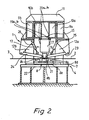
- the welding apparatus 1 illustrated in Figs 1 and 2 is intended for welding together two workpieces 2 and 3, such as aluminium profile sections or steel plates, to form an intermediate or final product, such as an aluminium or steel panel.
- the apparatus comprises a worktable 4, an upper machine frame 5 supported on the worktable, and a welding unit 6.
- the worktable consists of a stationary, stable and horizontal machine table 7, on which a backing unit 8 is mounted for movement transversely across the direction of advancement of the welding unit.
- the backing unit 8 consists of three separate backing elements 8a, 8b and 8c, which are stationarily mounted on a mobile plate 8d, the latter in turn being mounted on a plate 8e, which is stationarily mounted on the machine table.
- Lateral movements of plate 8d relative to plate 8e could be effected e.g. by means of a pressure cylinder, not shown.
- Securing means, not shown do, however, prevent the plate 8d from being displaced laterally during the welding operation proper.
- the machine frame 5 consists of an outer pair of beams 9a and 9b and an inner pair of beams 10a and 10b, the beams 9a and 9b of the outer pair being connected to the beams 10a and 10b of the inner pair by means of bolt connections, not shown, provided at the respective outer beam-ends.
- the beams 9a and 9b of the outer pair are also interconnected by means of a yoke 11 and they rest on the machine table 7 by means of two pillars 12a and 12b each, positioned at the outer ends of the beams.
- the welding unit 6 consists of a friction stir welding head 13, which is mounted on a carriage 15, the latter being disposed on the inner pair of beams 10a and 10b for movement thereon.
- the carriage is displaceable along the joint line of the workpieces by means of a drive unit, such as a motor, not shown.
- the friction stir welding head 13 is fitted with a guide mechanism, not shown, and, as appears from Fig 3a, with a welding probe 16 consisting of a frustro-conical body 16a and a pin 16b joined thereto, and during the welding operation, said pin is positioned between the workpieces in contact with those edges thereof that are to be joined together.
- the upper part of the body is connected to a rotating spindle 17, which is driven by a drive unit, such as a drive motor, not shown.
- a drive unit such as a drive motor
- the body and the pin of the welding probe could be configured e.g. in conformity with any of the embodiments illustrated in WO93/10935 or in WO95/26254 .
- Two guide shoes 19a and 19b interconnect the carriage 15 and the beams 10a and 10b, respectively, of the inner pair of beams, and the shoes are arranged to run along two beam-mounted guide rails 20a and 20b, respectively. This arrangement produces a rectilinear motion relative to the machine frame 5 and the worktable 4.
- each clamping means 21 and 22 press the workpieces 2 and 3, respectively, against the worktable 4 in the direction towards one another.
- Each clamping means 21 and 22 consists of a triangular pressure member, which via two arms 23 and 24, respectively, are pressed into engagement with the associated workpiece 2 and 3, respectively, during welding, by means of pressure cylinders 25 and 26, respectively.
- the pressure cylinders 25 and 26 are connected to the machine frame 5.
- the clamping means are positioned opposite one another in pairs along the edges of the joint between the workpieces. According to the present embodiment, the distance between the centre lines of two neighbouring pairs is about 500 mm.
- the backing element 8b is formed with a plane upper face, against which abut the lower faces of the workpieces during the friction stir welding performed by the welding probe 16. To produce an article having an even upper face this variety of the backing element therefore may be used only to weld together workpieces of identical material thickness.
- the backing element 8c formed with a stepped upper surface is used instead, see Fig 3b, the height of the step in the backing element equalling the difference in thickness.
- backing element 8a is used, wherein the height of the step has been adapted to the width of the workpiece 2.
- the plate 8d is displaced, in-between the welding operations, relative to the joint line of the workpieces, thus ensuring that the workpieces are supported by a correctly configured backing element during the welding.
- Fig 4 illustrates an alternative embodiment of the welding apparatus according to which the backing unit consists of an additional friction stir welding head 30.
- the backing unit consists of an additional friction stir welding head and a backing part, for instance in the form of a separate backing element. It is placed in front of the friction stir welding head 13 but on the opposite side of the joint line between the workpieces 2, 3.
- the additional friction stir welding head 30 is supported by a separate carriage 31, which by means of a drive unit, not shown, may be displaced along the joint line during the welding.
- the machine table 7 is formed with an inner cavity wherein are located the welding head 30 and the carriage 31.
- the carriage 31 is connected to the machine table by means of two guide shoes 31a arranged to run along two guide rails 31b. In turn, the latter are connected to the machine table via a beam 31c. Owing to this arrangement, a rectilinear movement is produced relative to the worktable 4.
- This alternative embodiment is particularly suitable to weld together hollow profile sections. It may also be used to weld together solid workpieces the material thickness of which exceeds 10 mm. It is likewise possible to replace the welding head 30 and the carriage 31 by a stationary backing element, which is placed on the guide rails 31b, or by a movable backing roller.
- Fig 5 shows one embodiment of the welding apparatus according to which the backing unit consists of an additional friction stir welding head 32, like in the embodiment of Fig 5. Also this head is placed in front of the friction stir welding head 13 although on the opposite side of the joint line between the workpieces 2 and 3.
- the friction stir welding head 32 is displaced along the joint line during the welding operation, by means of a carriage, not shown, of a kind similar to carriage 31.
- the additional friction stir welding head 32 is, however, arranged to be displaced by a means 33 in the shape of a cradle, from the position it assumes in this drawing figure to a position above the joint line of the workpieces.
- the welding head and the cradle 33 are provided with guides 34 and 35, respectively, whereby it becomes possible to transfer the additional welding head 32 from the carriage to the cradle, whereafter it may be pivoted over up to 180° following disconnection of all connecting means. In this position, point a meets point b, and thereafter it becomes possible to place the welding head on the same track as the upper friction stir welding head 13. To replace the lower friction stir welding head 32 it becomes necessary to place, on top of the machine table 7, a backing unit for example of the same kind as that shown in Fig 2.
- both welding heads above the joint line of the workpieces, in the centre of said line, and thereafter moving the welding heads in the direction towards the end points of the joint line, it thus becomes possible to perform the welding-together the workpieces in question in half the time compared with that required when there is only one welding head above the workpieces.
- the additional welding head is capable of either serving as a backing unit or be part of the welding unit, the resulting welding apparatus is extremely flexible.
- the friction stir welding probe is caused to rotate at a predetermined speed while at the same time it is being moved along the gap at a predetermined speed.
- the workpiece edges to be joined together will be plasticized by the frictional heat generated in this process, while at the same time they will be pressed against the worktable. After solidification, a homogeneous welded joint is formed, possessing high-strength qualities.
Landscapes
- Engineering & Computer Science (AREA)
- Mechanical Engineering (AREA)
- Pressure Welding/Diffusion-Bonding (AREA)
Description
- The present invention relates to an apparatus for friction stir welding, comprising a welding unit including a welding head, a worktable including a backing unit to support the workpieces to be welded together along their joint line, and clamping means to clamp the workpieces to the worktable during the welding operation.
- The definition friction stir welding designates a welding method according to which the workpieces to be joined together are plasticized along their joint line by supply of frictional heat from a rotating welding probe, the rotational axis of which extends essentially at right angles to the surface of the workpiece, and said welding probe is mounted on a welding head, which displaces the welding probe along the joint between the workpieces while at the same time it is being pressed against the workpieces. As described in
WO93/10935 WO95/26254 - The friction stir welding technique is particularly suitable for welding together aluminium profile sections for construction of large-size aluminium plating intended for example for hulls. The reason therefor is that this welding technique produces a welded joint the bottom face of which has a fine and smooth finish, with resulting few points of load concentration. In addition, the strength of the joint produced by this joining method is almost equal to that of the basic material. The considerable forces to which the workpieces are exposed during the very welding operation do, however, place considerable demands upon the stability of the worktable and on the ability of the clamping means to fix the workpieces in position.
- In addition, this welding technique can only be used to join together workpieces that are separated by a very narrow air gap. Should the air gap exceed this critical value, which among other things depends on the thickness of the profile sections, a joint is produced having internal cavities and impaired strength. In consequence thereof, extruded aluminium profile sections that cannot be produced to exactly precise dimensions by existing manufacturing methods, sometimes require some pre-treatment to avoid too large gaps between the profile sections. This is particularly important in the case of the welding together of elongate profile sections, in which even small deformations may give rise to unacceptable deviations.
- Considering that deformations in the profile sections may occur also during the friction stir welding operation proper, since the sections are exposed to the effects of heat, the dimensions of the end product may fail to be within the acceptable tolerance range, despite the pre-treatment of the profile sections. The deformations are smaller than in the case of MIG and TIG welding, since the temperature never reaches the fusing point.
- Another consequence of the critical size of the air gap is that the workpieces must not move relative to one another once they have been fixed in this correct welding position. In other words, high demands are placed also on the ability of the clamping means to fix the positions of the workpieces. Considering that the welding probe must be in contact with both workpieces during the welding operation, high demands are placed also on the running accuracy of the welding head.
- In order to meet the above criteria, a complex and consequently expensive welding apparatus is required.
- In addition, in order to ensure a reasonable repayment period for an investment of this magnitude, another requirement is that the welding apparatus possess a high degree of availability, which means that the time required to adjust the welding apparatus to the configuration of the workpieces, the thickness of the material, the desired appearance of the intended joint, for example as a corner joint, etcetera, in principle should be negligible while at the same time the above-mentioned demands concerning the small air-gap size etcetera should be met. This is a considerable problem in workshops, where one wishes for example to weld together hollow profile sections during part of the working day and solid workpieces having identical or different material thickness during another part of the day, without having to resort to time-consuming re-setting operations when shifting from one mode of operation to another, while at the same time the production of a high-precision welded joint to be formed along the joint line of the workpieces must be guaranteed-.
- The object of the present invention therefore is to make it possible to weld together workpieces of various configurations by means of the above welding apparatus without requiring time-consuming re-settings.
- This object is achieved in accordance with the teaching of the present invention by means of a welding apparatus as defined in
claims 1 and 8. - Owing to the two-part design of the welding apparatus backing unit, consisting of at least two backing parts or of at least one backing part and one additional welding head, it becomes possible, during operation, to rapidly re-set the welding apparatus before each welding operation, from a welding mode according to which solid workpieces the material of which is of equal or different thickness are welded together, to a welding mode according to which workpieces in the form of hollow profile sections are welded together.
- The backing parts and/or the additional welding head may be displaceable in a direction perpendicular to the joint line of the workpieces.
- The welding unit and the clamping means may be displaceable in a direction perpendicular to the direction of movement of the welding unit relative to the backing unit in order to allow the joint line of the workpieces to be changed. At least one backing part may be formed with an even-level upper face or with a stepped upper face. One backing part may be a separate backing element, such as a bottom backing element.
- It is likewise possible for the backing unit to consist of three different backing elements, one of which could in this case be formed with a plane upper face whereas the other two backing elements be formed with a stepped upper face, the steps of the latter backing elements being of different heights.
- The welding apparatus may be fitted with a means for shifting the additional welding head from a position below the joint line of the workpieces to a position above said line. The additional welding head preferably is a friction stir welding head.
- The invention will be described in more detail in the following with reference to the accompanying drawings, which for exemplifying purposes show various embodiments of a welding apparatus in accordance with the present invention.
- Fig 1 is a view from the front of a welding apparatus in accordance with a first embodiment.
- Fig 2 is a cross-sectional view of the welding apparatus of Fig 1, the section being taken on line II-II.
- Figs 3a, 3b and 3c are enlarged views of a portion of the welding apparatus of Fig 2, showing the backing unit of the welding apparatus in different positions.
- Fig 4 is a cross-sectional view of a second embodiment of the welding apparatus.
- Fig 5 is a view from the front of a welding apparatus in accordance with a third embodiment.
- The welding apparatus 1 illustrated in Figs 1 and 2 is intended for welding together two
workpieces upper machine frame 5 supported on the worktable, and awelding unit 6. In the subject case the worktable consists of a stationary, stable and horizontal machine table 7, on which abacking unit 8 is mounted for movement transversely across the direction of advancement of the welding unit. Thebacking unit 8 consists of threeseparate backing elements mobile plate 8d, the latter in turn being mounted on aplate 8e, which is stationarily mounted on the machine table. Lateral movements ofplate 8d relative toplate 8e could be effected e.g. by means of a pressure cylinder, not shown. Securing means, not shown, do, however, prevent theplate 8d from being displaced laterally during the welding operation proper. - The
machine frame 5 consists of an outer pair ofbeams beams beams beams beams yoke 11 and they rest on the machine table 7 by means of twopillars - In this embodiment the
welding unit 6 consists of a frictionstir welding head 13, which is mounted on acarriage 15, the latter being disposed on the inner pair ofbeams stir welding head 13 is fitted with a guide mechanism, not shown, and, as appears from Fig 3a, with awelding probe 16 consisting of a frustro-conical body 16a and apin 16b joined thereto, and during the welding operation, said pin is positioned between the workpieces in contact with those edges thereof that are to be joined together. The upper part of the body is connected to a rotatingspindle 17, which is driven by a drive unit, such as a drive motor, not shown. The body and the pin of the welding probe could be configured e.g. in conformity with any of the embodiments illustrated inWO93/10935 WO95/26254 - Two
guide shoes 19a and 19b interconnect thecarriage 15 and thebeams guide rails 20a and 20b, respectively. This arrangement produces a rectilinear motion relative to themachine frame 5 and the worktable 4. - During welding, the clamping means 21 and 22 press the
workpieces arms workpiece pressure cylinders pressure cylinders machine frame 5. The clamping means are positioned opposite one another in pairs along the edges of the joint between the workpieces. According to the present embodiment, the distance between the centre lines of two neighbouring pairs is about 500 mm. - As appears from Fig 3a, the
backing element 8b is formed with a plane upper face, against which abut the lower faces of the workpieces during the friction stir welding performed by thewelding probe 16. To produce an article having an even upper face this variety of the backing element therefore may be used only to weld together workpieces of identical material thickness. On the other hand, when the thickness of the material of the workpieces varies, thebacking element 8c formed with a stepped upper surface is used instead, see Fig 3b, the height of the step in the backing element equalling the difference in thickness. For workpieces that are to be joined together by means of a corner joint,backing element 8a is used, wherein the height of the step has been adapted to the width of theworkpiece 2. Depending on the configuration of the workpieces to be welded together, theplate 8d is displaced, in-between the welding operations, relative to the joint line of the workpieces, thus ensuring that the workpieces are supported by a correctly configured backing element during the welding. - Fig 4 illustrates an alternative embodiment of the welding apparatus according to which the backing unit consists of an additional friction
stir welding head 30. The backing unit consists of an additional friction stir welding head and a backing part, for instance in the form of a separate backing element. It is placed in front of the frictionstir welding head 13 but on the opposite side of the joint line between theworkpieces stir welding head 30 is supported by aseparate carriage 31, which by means of a drive unit, not shown, may be displaced along the joint line during the welding. In accordance with this modified embodiment, the machine table 7 is formed with an inner cavity wherein are located thewelding head 30 and thecarriage 31. To ensure that the welding head probe assumes the same position relative to the joint line of the workpieces along the entire joint, thecarriage 31 is connected to the machine table by means of twoguide shoes 31a arranged to run along twoguide rails 31b. In turn, the latter are connected to the machine table via abeam 31c. Owing to this arrangement, a rectilinear movement is produced relative to the worktable 4. This alternative embodiment is particularly suitable to weld together hollow profile sections. It may also be used to weld together solid workpieces the material thickness of which exceeds 10 mm. It is likewise possible to replace thewelding head 30 and thecarriage 31 by a stationary backing element, which is placed on theguide rails 31b, or by a movable backing roller. - Fig 5, finally, shows one embodiment of the welding apparatus according to which the backing unit consists of an additional friction
stir welding head 32, like in the embodiment of Fig 5. Also this head is placed in front of the frictionstir welding head 13 although on the opposite side of the joint line between theworkpieces stir welding head 32 is displaced along the joint line during the welding operation, by means of a carriage, not shown, of a kind similar tocarriage 31. The additional frictionstir welding head 32 is, however, arranged to be displaced by ameans 33 in the shape of a cradle, from the position it assumes in this drawing figure to a position above the joint line of the workpieces. The welding head and thecradle 33 are provided withguides additional welding head 32 from the carriage to the cradle, whereafter it may be pivoted over up to 180° following disconnection of all connecting means. In this position, point a meets point b, and thereafter it becomes possible to place the welding head on the same track as the upper frictionstir welding head 13. To replace the lower frictionstir welding head 32 it becomes necessary to place, on top of the machine table 7, a backing unit for example of the same kind as that shown in Fig 2. By placing both welding heads above the joint line of the workpieces, in the centre of said line, and thereafter moving the welding heads in the direction towards the end points of the joint line, it thus becomes possible to perform the welding-together the workpieces in question in half the time compared with that required when there is only one welding head above the workpieces. Because the additional welding head is capable of either serving as a backing unit or be part of the welding unit, the resulting welding apparatus is extremely flexible. - When the
workpieces - The friction stir welding probe is caused to rotate at a predetermined speed while at the same time it is being moved along the gap at a predetermined speed. As explained in the introduction hereto, the workpiece edges to be joined together will be plasticized by the frictional heat generated in this process, while at the same time they will be pressed against the worktable. After solidification, a homogeneous welded joint is formed, possessing high-strength qualities. When the friction
stir welding probe 16 has traversed the entire joint and the individual welding operation thus is completed, thepressure cylinders - It should be appreciated that the invention is not limited to the above embodiments but that numerous modifications are possible within the scope of the appended claims. In order to further increase the capacity of the welding apparatus a number of friction stir welding heads could be placed above and/or underneath the workpieces. The welding head/heads could be fitted with special mounting and transportation means in order to facilitate the shifting of the various welding heads between different welding apparatuses. It is likewise possible to use a pallet or transfer carriage system to move and connect the welding heads to different welding apparatuses.
- In the description above, the starting position wherein a backing unit in the form of a backing element and a welding head operating vertically above said element has been used, but obviously the welding may be performed from below, against a backing unit positioned in contact with the upper face, or with vertically orientated workpieces and horizontally directed welding. In a welding apparatus of Fig 4, the upper head could in this case be replaced by a backing unit and the welding be performed from underneath.
Claims (11)
- An apparatus (1) for friction stir welding, comprising a welding unit (6) including a welding head (13), a worktable (4) and a backing unit (8) to support the workpieces (2, 3) to be welded together along their joint line and clamping means (21, 22) to clamp the workpieces (2, 3) to the worktable (4) in a direction towards one another during the welding operation, characterised in that the backing unit (8) consists of at least two backing parts (8a, b, c), said backing parts (8a, b, c) being freely exchangeable one for the other and vice-versa, before each welding operation, in that at least a part (8a, b, c, d) of said backing unit (8) is displaceable in a direction perpendicular to the joint line of the workpieces (2, 3), and in that the apparatus (1) comprises securing means that prevent the backing unit (8) from being displaced laterally during the welding operation.
- An apparatus as claimed in claim 1, characterised in that the welding unit (6) and the clamping means (21, 22) are displaceable in a direction perpendicular to the direction of movement of the welding unit relative to the backing unit (8) in order to allow displacement of the joint line of the workpieces (2, 3).
- An apparatus as claimed in any one of the preceding claims, characterised in that at least one backing part (8b) has a plane upper face.
- An apparatus as claimed in any one of the preceding claims, characterised in that at least one backing part (8a, 8b) has a stepped upper face.
- An apparatus as claimed in any one of the preceding claims, characterised in that one backing part is a separate backing element (8a, 8b, 8c), such as a bottom backing.
- An apparatus as claimed in claim 5, characterised in that the backing unit consists of three separate backing elements (8a, 8b, 8c).
- An apparatus as claimed in claim 6, characterised in that one (8b) of the backing elements is formed with a plane upper face and in that the two other backing elements (8a, 8c) are formed with a stepped upper face, the steps of the two latter backing elements being of different heights.
- An apparatus (1) for friction stir welding, comprising a welding unit (6) including a welding head (13), a worktable (4) and a backing unit to support the workpieces (2, 3) to be welded together along their joint line and clamping means (21, 22) to clamp the workpieces (2, 3) to the worktable (4) in a direction towards one another during the welding operation, characterised in that the backing unit consists of at least one backing part and one additional stir welding head (30), said at least one backing part being freely exchangeable with the additional stir welding head (30) before each welding operation and vice-versa, and in that the additional stir welding head (30) is supported by a carriage (31) such that it may be displaced along the joint line during welding.
- An apparatus as claimed in claim 8, characterised in that said at least one backing part and/or the additional welding head (30) is/are displaceable in a direction perpendicular to the joint line of the workpieces (2, 3).
- An apparatus as claimed in any one of claims 8 or 9, characterised in that the welding unit (6) and the clamping means (21, 22) are displaceable in a direction perpendicular to the direction of movement of the welding unit relative to the backing unit (8; 30) in order to allow displacement of the joint line of the workpieces (2, 3).
- An apparatus as claimed in any one of the claims 8-10, characterised by a means for shifting the additional welding head (32) from a position underneath the joint line of the workpieces (2, 3) to a position above said line.
Applications Claiming Priority (3)
| Application Number | Priority Date | Filing Date | Title |
|---|---|---|---|
| SE9704800A SE9704800D0 (en) | 1997-12-19 | 1997-12-19 | Device for welding |
| SE9704800 | 1997-12-19 | ||
| PCT/SE1998/002390 WO1999034951A1 (en) | 1997-12-19 | 1998-12-18 | Apparatus for friction stir welding |
Publications (2)
| Publication Number | Publication Date |
|---|---|
| EP1091825A1 EP1091825A1 (en) | 2001-04-18 |
| EP1091825B1 true EP1091825B1 (en) | 2007-11-21 |
Family
ID=20409506
Family Applications (1)
| Application Number | Title | Priority Date | Filing Date |
|---|---|---|---|
| EP98964644A Expired - Lifetime EP1091825B1 (en) | 1997-12-19 | 1998-12-18 | Apparatus for friction stir welding |
Country Status (7)
| Country | Link |
|---|---|
| US (1) | US6419142B1 (en) |
| EP (1) | EP1091825B1 (en) |
| AU (1) | AU1992199A (en) |
| DE (1) | DE69838760T2 (en) |
| NO (1) | NO330040B1 (en) |
| SE (1) | SE9704800D0 (en) |
| WO (1) | WO1999034951A1 (en) |
Cited By (2)
| Publication number | Priority date | Publication date | Assignee | Title |
|---|---|---|---|---|
| CN106181183A (en) * | 2016-08-24 | 2016-12-07 | 中国航天科技集团公司长征机械厂 | The simple inner support clamp of agitating friction girth welding |
| CN112317949A (en) * | 2020-10-20 | 2021-02-05 | 惠州哈尔滨工业大学国际创新研究院 | Friction stir welding device |
Families Citing this family (57)
| Publication number | Priority date | Publication date | Assignee | Title |
|---|---|---|---|---|
| CN1322241C (en) * | 1996-03-19 | 2007-06-20 | 株式会社日立制作所 | Friction welding method and structure body formed by friction welding |
| ES2177010T3 (en) * | 1997-05-16 | 2002-12-01 | Esab Ab | WELDING ASSEMBLY FOR AGITATION AND FRICTION WELDING. |
| DE69712078T2 (en) * | 1997-12-19 | 2002-12-12 | Esab Ab, Goeteborg/Gothenburg | welding device |
| DE19957136C1 (en) * | 1999-11-18 | 2001-02-08 | Geesthacht Gkss Forschung | Friction welding appts has a projecting and rotating pin to act on the workpiece materials at the welding zone to follow the welding line and soften the materials to fuse together and bond sheet plates with complex shapes |
| GB0008919D0 (en) * | 2000-04-11 | 2000-05-31 | British Aerospace | Solid phase welding |
| CA2409489C (en) | 2000-05-08 | 2009-01-20 | Brigham Young University | Friction stir welding using a superabrasive tool |
| JP3763734B2 (en) * | 2000-10-27 | 2006-04-05 | 株式会社日立製作所 | Panel member processing method |
| GB0027277D0 (en) * | 2000-11-08 | 2000-12-27 | Stolt Offshore Ltd | Connecting conduits for fluids |
| CN1257036C (en) * | 2001-03-29 | 2006-05-24 | 马自达汽车株式会社 | Connection method and device using friction stirring |
| JP4195206B2 (en) * | 2001-04-04 | 2008-12-10 | 株式会社日立製作所 | Friction stir welding equipment |
| US6732901B2 (en) | 2001-06-12 | 2004-05-11 | Brigham Young University Technology Transfer Office | Anvil for friction stir welding high temperature materials |
| JP2003048063A (en) | 2001-08-01 | 2003-02-18 | Mazda Motor Corp | Surface treatment method, member subjected to the surface treatment, and intermediate member subjected to the surface treatment |
| US6543671B2 (en) * | 2001-09-05 | 2003-04-08 | Lockheed Martin Corporation | Apparatus and method for friction stir welding using filler material |
| US6708866B2 (en) * | 2001-09-26 | 2004-03-23 | Nova-Tech Engineering, Inc. | Method and apparatus for machine tooling, such as friction stir welder |
| US6595407B2 (en) * | 2001-10-16 | 2003-07-22 | Unova Ip Corp. | Flexible framing station tool gate changing method and apparatus |
| JP2004141898A (en) * | 2002-10-23 | 2004-05-20 | Hitachi Ltd | Friction stir welding method and apparatus |
| WO2004067218A2 (en) | 2003-01-30 | 2004-08-12 | Smith International, Inc. | Out-of-position stir welding of high melting temperature alloys |
| US7530486B2 (en) | 2003-05-05 | 2009-05-12 | Sii Megadiamond, Inc. | Applications of friction stir welding using a superabrasive tool |
| EP1667811A4 (en) | 2003-08-04 | 2008-08-27 | Sii Megadiamond Inc | CRACK REPAIR USING AGITATION FRICTION WELDING ON MATERIALS COMPRISING METAL MATRIX COMPOSITES, FERROUS ALLOYS, NON-FERROUS ALLOYS AND SUPERALLIAGES |
| US7448528B2 (en) * | 2003-08-12 | 2008-11-11 | The Boeing Company | Stir forming apparatus and method |
| US20060032333A1 (en) | 2004-03-24 | 2006-02-16 | Steel Russell J | Solid state processing of industrial blades, edges and cutting elements |
| FR2869248B1 (en) * | 2004-04-27 | 2007-06-29 | Snecma Moteurs Sa | PROCESS FOR BINDING BY FRICTION WELDING OF A HOLE OF A METAL PIECE |
| US20100078224A1 (en) | 2004-05-21 | 2010-04-01 | Smith International, Inc. | Ball hole welding using the friction stir welding (fsw) process |
| WO2006044215A2 (en) | 2004-10-05 | 2006-04-27 | Smith International, Inc. | Expandable mandrel for use in friction stir welding |
| US20070057015A1 (en) * | 2005-09-09 | 2007-03-15 | Kevin Colligan | Tapered friction stir welding and processing tool |
| US9511445B2 (en) | 2014-12-17 | 2016-12-06 | Aeroprobe Corporation | Solid state joining using additive friction stir processing |
| US20080041921A1 (en) | 2005-09-26 | 2008-02-21 | Kevin Creehan | Friction stir fabrication |
| US8632850B2 (en) | 2005-09-26 | 2014-01-21 | Schultz-Creehan Holdings, Inc. | Friction fabrication tools |
| US8875976B2 (en) | 2005-09-26 | 2014-11-04 | Aeroprobe Corporation | System for continuous feeding of filler material for friction stir welding, processing and fabrication |
| US9511446B2 (en) | 2014-12-17 | 2016-12-06 | Aeroprobe Corporation | In-situ interlocking of metals using additive friction stir processing |
| US9266191B2 (en) | 2013-12-18 | 2016-02-23 | Aeroprobe Corporation | Fabrication of monolithic stiffening ribs on metallic sheets |
| US8550326B2 (en) | 2005-10-05 | 2013-10-08 | Megastir Technologies Llc | Expandable mandrel for use in friction stir welding |
| US8056797B2 (en) | 2005-10-05 | 2011-11-15 | Megastir Technologies | Expandable mandrel for use in friction stir welding |
| WO2007124872A1 (en) * | 2006-04-27 | 2007-11-08 | Sms Demag Ag | Apparatus for the connection of strips |
| US7966713B2 (en) * | 2006-05-17 | 2011-06-28 | The Boeing Company | Tooling head mounted structural positioning |
| US20080023529A1 (en) * | 2006-07-25 | 2008-01-31 | Larry Van Reatherford | Ultrasonic welding apparatus |
| US7992761B2 (en) * | 2006-10-05 | 2011-08-09 | The Boeing Company | Process control system for friction stir welding |
| US20080217377A1 (en) * | 2007-03-06 | 2008-09-11 | Alcoa Inc. | Fracture Resistant Friction Stir Welding Tool |
| US7793816B2 (en) * | 2007-09-07 | 2010-09-14 | Alcoa Inc. | Friction stir welding apparatus |
| DE102007052801B4 (en) * | 2007-11-06 | 2010-10-07 | Bruker Daltonik Gmbh | Ion mobility spectrometer with substance collector |
| US7854362B2 (en) * | 2008-03-14 | 2010-12-21 | Alcoa Inc. | Advanced multi-shouldered fixed bobbin tools for simultaneous friction stir welding of multiple parallel walls between parts |
| US20100006622A1 (en) * | 2008-07-10 | 2010-01-14 | Smith Christopher B | Self-clamping friction stir welding device |
| US8322176B2 (en) * | 2009-02-11 | 2012-12-04 | Ford Global Technologies, Llc | System and method for incrementally forming a workpiece |
| BR112012004131B1 (en) * | 2009-08-31 | 2017-09-26 | Mitsubishi-Hitachi Metals Machinery, Inc | METHOD AND APPLICATION OF WELDING ATTENTION ON BOTH SIDES, METHOD OF JUNCTION OF METAL PLATES IN COLD LAMINATION SYSTEM, AND COLD LAMINATION SYSTEM |
| JP2013509301A (en) | 2009-11-02 | 2013-03-14 | メガスター・テクノロジーズ・エルエルシー | Misalignment friction stir welding of casing and small diameter pipes or small diameter pipes |
| WO2013002869A2 (en) | 2011-04-07 | 2013-01-03 | Schultz-Creehan Holdings, Inc. | System for continuous feeding of filler material for friction stir fabrication and self-reacting friction stir welding tool |
| AU2012369243B2 (en) * | 2012-02-09 | 2015-02-05 | Esab Ab | Backing arrangement for use in friction stir welding |
| FR2995236B1 (en) * | 2012-09-07 | 2015-05-01 | Airbus Operations Sas | IMPROVED METHOD AND SYSTEM FOR FRICTION WELDING MIXING OF A STIFFENER ON AN AIRCRAFT PANEL |
| FR2995237B1 (en) | 2012-09-07 | 2015-05-01 | Airbus Operations Sas | IMPROVED FRICTION MIXING WELDING SYSTEM COMPRISING MOBILE BACK SUPPORT. |
| US9174302B2 (en) | 2013-02-01 | 2015-11-03 | Fluor Technologies Corporation | Friction stir welding devices and methods for tandem tool and anvil |
| GB2526122B (en) * | 2014-05-14 | 2016-09-14 | Acergy France SAS | Fabrication of pipe strings using friction stir welding |
| GB2526121B (en) * | 2014-05-14 | 2017-02-01 | Acergy France SAS | Fabrication of pipe strings using friction stir welding |
| JP2016128177A (en) * | 2015-01-09 | 2016-07-14 | 株式会社Ihi | Friction agitation joining device |
| JP6696809B2 (en) * | 2016-03-29 | 2020-05-20 | 株式会社総合車両製作所 | Friction stir welding backing material and friction stir welding method |
| WO2017169992A1 (en) * | 2016-03-31 | 2017-10-05 | Jfeスチール株式会社 | Method and device for friction stir bonding of structural steel |
| AU2018359514C1 (en) | 2017-10-31 | 2021-05-27 | MELD Manufacturing Corporation | Solid-state additive manufacturing system and material compositions and structures |
| CN108637454A (en) * | 2018-05-14 | 2018-10-12 | 湖南文理学院 | A kind of agitating friction soldering equipment improving protecting effect convenient for remote control |
Family Cites Families (16)
| Publication number | Priority date | Publication date | Assignee | Title |
|---|---|---|---|---|
| DE1116034B (en) | 1958-03-07 | 1961-10-26 | Knapsack Ag | Method and device for welding bands together |
| DE1627555C3 (en) | 1967-07-19 | 1974-03-21 | Messer Griesheim Gmbh, 6000 Frankfurt | Device for trimming and welding together strip ends to be welded together |
| SE362813B (en) | 1973-03-15 | 1973-12-27 | Mitsui Shipbuilding Eng | |
| FR2241376B1 (en) | 1973-08-22 | 1976-11-19 | Etpm | |
| DE3502368A1 (en) | 1985-01-25 | 1986-07-31 | Thyssen Stahl AG, 4100 Duisburg | METHOD FOR BUTT WELDING OF AT LEAST ONE-PIECE GALVANIZED, IN PARTICULAR THAT DRAWABLE, STEEL SHEETS OR STEEL TAPES |
| US5607726A (en) | 1994-10-17 | 1997-03-04 | E. I. Du Pont De Nemours And Company | Process for the preparation of composite coatings with variable thickness |
| CN1322241C (en) * | 1996-03-19 | 2007-06-20 | 株式会社日立制作所 | Friction welding method and structure body formed by friction welding |
| US5697544A (en) * | 1996-03-21 | 1997-12-16 | Boeing North American, Inc. | Adjustable pin for friction stir welding tool |
| US5794835A (en) * | 1996-05-31 | 1998-08-18 | The Boeing Company | Friction stir welding |
| JP3070735B2 (en) * | 1997-07-23 | 2000-07-31 | 株式会社日立製作所 | Friction stir welding method |
| DE69712078T2 (en) * | 1997-12-19 | 2002-12-12 | Esab Ab, Goeteborg/Gothenburg | welding device |
| US5971247A (en) * | 1998-03-09 | 1999-10-26 | Lockheed Martin Corporation | Friction stir welding with roller stops for controlling weld depth |
| JP2000153374A (en) * | 1998-11-18 | 2000-06-06 | Hitachi Ltd | Friction stir welding device, friction stir welding tool, and friction stir welding structure |
| US6257479B1 (en) * | 1999-12-07 | 2001-07-10 | The Boeing Company | Tooling and methods for circumferential friction stir welding |
| US6173880B1 (en) * | 1999-12-08 | 2001-01-16 | The United States Of America As Represented By The Administrator Of The National Aeronautics And Space Administration | Friction stir weld system for welding and weld repair |
| US6237835B1 (en) * | 2000-02-29 | 2001-05-29 | The Boeing Company | Method and apparatus for backing up a friction stir weld joint |
-
1997
- 1997-12-19 SE SE9704800A patent/SE9704800D0/en unknown
-
1998
- 1998-12-18 WO PCT/SE1998/002390 patent/WO1999034951A1/en not_active Ceased
- 1998-12-18 DE DE69838760T patent/DE69838760T2/en not_active Expired - Lifetime
- 1998-12-18 EP EP98964644A patent/EP1091825B1/en not_active Expired - Lifetime
- 1998-12-18 AU AU19921/99A patent/AU1992199A/en not_active Abandoned
- 1998-12-18 US US09/582,005 patent/US6419142B1/en not_active Expired - Lifetime
-
2000
- 2000-06-15 NO NO20003062A patent/NO330040B1/en not_active IP Right Cessation
Cited By (2)
| Publication number | Priority date | Publication date | Assignee | Title |
|---|---|---|---|---|
| CN106181183A (en) * | 2016-08-24 | 2016-12-07 | 中国航天科技集团公司长征机械厂 | The simple inner support clamp of agitating friction girth welding |
| CN112317949A (en) * | 2020-10-20 | 2021-02-05 | 惠州哈尔滨工业大学国际创新研究院 | Friction stir welding device |
Also Published As
| Publication number | Publication date |
|---|---|
| AU1992199A (en) | 1999-07-26 |
| US6419142B1 (en) | 2002-07-16 |
| DE69838760D1 (en) | 2008-01-03 |
| NO20003062D0 (en) | 2000-06-15 |
| SE9704800D0 (en) | 1997-12-19 |
| WO1999034951A1 (en) | 1999-07-15 |
| EP1091825A1 (en) | 2001-04-18 |
| NO330040B1 (en) | 2011-02-07 |
| NO20003062L (en) | 2000-08-17 |
| DE69838760T2 (en) | 2008-10-30 |
Similar Documents
| Publication | Publication Date | Title |
|---|---|---|
| US6419142B1 (en) | Apparatus for friction stir welding | |
| EP0928659B1 (en) | Welding apparatus | |
| EP0910492B1 (en) | Plant for friction stir welding | |
| EP0929375B1 (en) | Apparatus for friction stir welding | |
| EP1211014B1 (en) | Device and method for seam welding | |
| JP4371669B2 (en) | Welding jig | |
| KR100459094B1 (en) | Structure body of railway vehicle | |
| JP2000334577A (en) | Joining apparatus and joining method | |
| JP3581131B2 (en) | Laser welding system | |
| JP3661923B2 (en) | Mash seam welding equipment | |
| US20060163327A1 (en) | Method of manufacturing cylindrical body, friction stir welding method, and friction stir welding device | |
| KR200375423Y1 (en) | Tailor welded blank welding system | |
| JP3504062B2 (en) | Strip positioning device | |
| US8387852B2 (en) | Welded tailored blanks that allow for part curvature | |
| CN220127838U (en) | Friction stir welding is with pressing from both sides tight frock | |
| CN119016824A (en) | Laser welding device and method for special-shaped titanium alloy thin-walled parts | |
| JP6059649B2 (en) | Double-side friction stir welding method and double-side friction stir welding apparatus | |
| CN114905137B (en) | Device based on EMUs side wall board friction stir welding technology | |
| CA2258524C (en) | Plant for friction stir welding | |
| CN224222766U (en) | Machine tool machining system | |
| JPS6258844B2 (en) | ||
| JP2597259B2 (en) | Method and apparatus for controlling welding angle deformation | |
| KR20240176720A (en) | Profile Machining Device | |
| JPH03285767A (en) | Device for pressing materials to be welded of automatic welding equipment for welded structural beam | |
| CN121199419A (en) | A welding fixture for easy alignment welding workstations |
Legal Events
| Date | Code | Title | Description |
|---|---|---|---|
| PUAI | Public reference made under article 153(3) epc to a published international application that has entered the european phase |
Free format text: ORIGINAL CODE: 0009012 |
|
| 17P | Request for examination filed |
Effective date: 20000609 |
|
| AK | Designated contracting states |
Kind code of ref document: A1 Designated state(s): BE CH DE FI FR GB IT LI NL SE |
|
| 17Q | First examination report despatched |
Effective date: 20021217 |
|
| GRAP | Despatch of communication of intention to grant a patent |
Free format text: ORIGINAL CODE: EPIDOSNIGR1 |
|
| GRAS | Grant fee paid |
Free format text: ORIGINAL CODE: EPIDOSNIGR3 |
|
| GRAA | (expected) grant |
Free format text: ORIGINAL CODE: 0009210 |
|
| AK | Designated contracting states |
Kind code of ref document: B1 Designated state(s): BE CH DE FI FR GB IT LI NL SE |
|
| REG | Reference to a national code |
Ref country code: GB Ref legal event code: FG4D |
|
| REG | Reference to a national code |
Ref country code: CH Ref legal event code: EP |
|
| REF | Corresponds to: |
Ref document number: 69838760 Country of ref document: DE Date of ref document: 20080103 Kind code of ref document: P |
|
| REG | Reference to a national code |
Ref country code: CH Ref legal event code: NV Representative=s name: ING. MARCO ZARDI C/O M. ZARDI & CO. S.A. |
|
| REG | Reference to a national code |
Ref country code: SE Ref legal event code: TRGR |
|
| ET | Fr: translation filed | ||
| PLBE | No opposition filed within time limit |
Free format text: ORIGINAL CODE: 0009261 |
|
| STAA | Information on the status of an ep patent application or granted ep patent |
Free format text: STATUS: NO OPPOSITION FILED WITHIN TIME LIMIT |
|
| 26N | No opposition filed |
Effective date: 20080822 |
|
| PGFP | Annual fee paid to national office [announced via postgrant information from national office to epo] |
Ref country code: FI Payment date: 20091221 Year of fee payment: 12 Ref country code: CH Payment date: 20091222 Year of fee payment: 12 |
|
| PGFP | Annual fee paid to national office [announced via postgrant information from national office to epo] |
Ref country code: NL Payment date: 20091221 Year of fee payment: 12 |
|
| REG | Reference to a national code |
Ref country code: NL Ref legal event code: V1 Effective date: 20110701 |
|
| REG | Reference to a national code |
Ref country code: CH Ref legal event code: PL |
|
| PG25 | Lapsed in a contracting state [announced via postgrant information from national office to epo] |
Ref country code: FI Free format text: LAPSE BECAUSE OF NON-PAYMENT OF DUE FEES Effective date: 20101218 |
|
| PG25 | Lapsed in a contracting state [announced via postgrant information from national office to epo] |
Ref country code: CH Free format text: LAPSE BECAUSE OF NON-PAYMENT OF DUE FEES Effective date: 20101231 Ref country code: LI Free format text: LAPSE BECAUSE OF NON-PAYMENT OF DUE FEES Effective date: 20101231 |
|
| PG25 | Lapsed in a contracting state [announced via postgrant information from national office to epo] |
Ref country code: NL Free format text: LAPSE BECAUSE OF NON-PAYMENT OF DUE FEES Effective date: 20110701 |
|
| REG | Reference to a national code |
Ref country code: FR Ref legal event code: PLFP Year of fee payment: 18 |
|
| REG | Reference to a national code |
Ref country code: FR Ref legal event code: PLFP Year of fee payment: 19 |
|
| PG25 | Lapsed in a contracting state [announced via postgrant information from national office to epo] |
Ref country code: IT Free format text: LAPSE BECAUSE OF NON-PAYMENT OF DUE FEES Effective date: 20151218 |
|
| PGRI | Patent reinstated in contracting state [announced from national office to epo] |
Ref country code: IT Effective date: 20170710 |
|
| REG | Reference to a national code |
Ref country code: FR Ref legal event code: PLFP Year of fee payment: 20 |
|
| PGFP | Annual fee paid to national office [announced via postgrant information from national office to epo] |
Ref country code: FR Payment date: 20171227 Year of fee payment: 20 |
|
| PGFP | Annual fee paid to national office [announced via postgrant information from national office to epo] |
Ref country code: BE Payment date: 20171227 Year of fee payment: 20 Ref country code: SE Payment date: 20171229 Year of fee payment: 20 Ref country code: GB Payment date: 20171227 Year of fee payment: 20 |
|
| PGFP | Annual fee paid to national office [announced via postgrant information from national office to epo] |
Ref country code: DE Payment date: 20171229 Year of fee payment: 20 |
|
| PGFP | Annual fee paid to national office [announced via postgrant information from national office to epo] |
Ref country code: IT Payment date: 20171221 Year of fee payment: 20 |
|
| REG | Reference to a national code |
Ref country code: DE Ref legal event code: R071 Ref document number: 69838760 Country of ref document: DE |
|
| REG | Reference to a national code |
Ref country code: GB Ref legal event code: PE20 Expiry date: 20181217 |
|
| REG | Reference to a national code |
Ref country code: BE Ref legal event code: MK Effective date: 20181218 |
|
| REG | Reference to a national code |
Ref country code: SE Ref legal event code: EUG |
|
| PG25 | Lapsed in a contracting state [announced via postgrant information from national office to epo] |
Ref country code: GB Free format text: LAPSE BECAUSE OF EXPIRATION OF PROTECTION Effective date: 20181217 |
|
| P01 | Opt-out of the competence of the unified patent court (upc) registered |
Effective date: 20230522 |