EP1091639B1 - Plant tray and cultivation system provided with such a plant tray - Google Patents
Plant tray and cultivation system provided with such a plant tray Download PDFInfo
- Publication number
- EP1091639B1 EP1091639B1 EP99929969A EP99929969A EP1091639B1 EP 1091639 B1 EP1091639 B1 EP 1091639B1 EP 99929969 A EP99929969 A EP 99929969A EP 99929969 A EP99929969 A EP 99929969A EP 1091639 B1 EP1091639 B1 EP 1091639B1
- Authority
- EP
- European Patent Office
- Prior art keywords
- plant
- plant tray
- accommodation
- tray according
- accommodations
- Prior art date
- Legal status (The legal status is an assumption and is not a legal conclusion. Google has not performed a legal analysis and makes no representation as to the accuracy of the status listed.)
- Expired - Lifetime
Links
Images

Classifications
-
- A—HUMAN NECESSITIES
- A01—AGRICULTURE; FORESTRY; ANIMAL HUSBANDRY; HUNTING; TRAPPING; FISHING
- A01G—HORTICULTURE; CULTIVATION OF VEGETABLES, FLOWERS, RICE, FRUIT, VINES, HOPS OR SEAWEED; FORESTRY; WATERING
- A01G9/00—Cultivation in receptacles, forcing-frames or greenhouses; Edging for beds, lawn or the like
- A01G9/02—Receptacles, e.g. flower-pots or boxes; Glasses for cultivating flowers
- A01G9/029—Receptacles for seedlings
- A01G9/0295—Units comprising two or more connected receptacles
-
- A—HUMAN NECESSITIES
- A01—AGRICULTURE; FORESTRY; ANIMAL HUSBANDRY; HUNTING; TRAPPING; FISHING
- A01G—HORTICULTURE; CULTIVATION OF VEGETABLES, FLOWERS, RICE, FRUIT, VINES, HOPS OR SEAWEED; FORESTRY; WATERING
- A01G22/00—Cultivation of specific crops or plants not otherwise provided for
- A01G22/35—Bulbs; Alliums, e.g. onions or leeks
Definitions
- the present invention relates to a plant tray according to the preamble of Claim 1.
- a plant tray of this type is disclosed in EP 0 758 524 A1. Tulip bulbs, but also other plants, are grown in such trays.
- Netherlands Laid Open Application 9200641 describes a plant tray wherein the bottom of each of the accommodations is closed. Bulbs are placed in these accommodations through insertion openings made at the top and water is then supplied. This water collects at the bottom and root growth occurs here. Because this water does not circulate, slime formation lakes place, which is disadvantageous for the further development of the bulb and, moreover, causes stench and rotting.
- a tray consisting of an essentially open container having a base surface from which a number of spikes or nails protrude onto which the bulbs concerned are pushed. There are thus no boundaries between the bulbs.
- Water is transported continuously or intermittently through a container of this type, as a result of which the problem of slime formation, stench and rotting is eliminated.
- the bulbs are arranged freely adjoining one another and it has been found that as a result of appreciable root formation and spread the bulbs can no longer be removed as individual items because the roots of adjacent bulbous plants become appreciably intertwined.
- This latter system is used in particular for long-term cultivation, for example ten weeks.
- the root development during such a long period can be appreciable. It is essential that the pins do not pierce through the root base because this causes irreparable damage to the plant. In practice it has been found that this does occur in particular cases.
- the plant is grown for a short time. Although the system of root formation described above is restricted to an appreciable extent, it is not completely eliminated. Furthermore, this means that the plant is stored dry for a longer period, as a result of which the quality could deteriorate. Moreover, the cultivation of such plants is seasonal and if the plant has to be moved again two weeks prior to harvest, this results in substantial peaks in the distribution of work, which is undesirable.
- EP 0 758 524 Al comprises square accommodations. each of which is always provided with finger-like retaining elements half way up the boundary walls. Each tray is open at the bottom.
- the aim of the present invention is to provide a plant tray with which the production of slime in the water in which the roots are standing is prevented, with which it is precluded that plants can no longer be removed because the roots of adjacent plants grow into one another and with which it is possible to carry out both a long cultivation (for example 10 weeks) and a short cultivation (for example 2 weeks).
- clamping means Stable positioning of the bulbous plants in the accommodations can be promoted by fitting clamping means.
- clamping means consist of plates which preferably extend perpendicularly to the periphery of the accommodations and delimit a tapered opening for such a bulbous plant. That is to say, the bulbous plant can be pushed firmly into the clamping means. No damage to the bulbs during further growth has been observed, such as has been found in the case of systems with which the roots are skewered on pins and the like. Fixing of the bulbs is facilitated if such plates are provided with a sharp cutting edge.
- the accommodations are made hexagonal and arranged in a honeycomb pattern. It has been found that optimum utilisation of the surface area of the tray is obtained in this way.
- the clamping plates preferably extend from one or more of the comers of the hexagons.
- the wall thickness of the trays and more particularly close to the cutting edge is preferably between 0.5 and 2.5 mm. In this way adequate strength is combined with the ability to cut the relatively soft root material.
- the actual cutting edge of the plates is preferably made thinner and is less than 2.5 mm.
- the invention does not relate exclusively to tulip bulbs, but other plants, such as hyacinths and narcissi, can also be cultivated using the invention.
- the plant tray described above is preferably used in combination with a cultivation system with which it is ensured that the roots of the bulbs come into contact with water.
- a water level must be chosen as a function of the depth to which the bulbs are pressed into the trays.
- the various features are implemented in such a way that the tray is placed in a container into which water is introduced, which water circulates continuously or periodically.
- an ebb/tide system can be used.
- Fig. 1 shows a plan view of a tray for cultivating tulip bulbs. This tray is indicated by 1.
- this tray is approximately 60 x 40 cm, but it must be understood that such dimensions are not of essential importance for the inventive concept.
- 90 - 150 accommodations for holding tulip bulbs have, for example, been made in the tray. This number will be different for other plants.
- the accommodations are indicated by reference numeral 2 and are hexagonal, the walls being indicated by 3.
- One accommodation is shown in detail in Fig. 2 and it can be seen that said accommodation is also provided with clamping plates 4, which are constructed such that they slope downwards at an angle, as well as with peripheral walls 3.
- the bottom edges of the accommodations 2 are indicated by 5.
- the clamping plates 4 are provided with cutting edges 12 and the edges have been made relatively sharp.
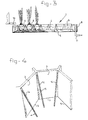
- Fig. 3 shows a combination of trays 1 with an ebb/tide system.
- the latter consists of a liquid-tight container provided with a water feed 10 and water discharge 11, the water level at the particular point in time being indicated by 9.
- the tray and/or the containers are provided with spacers.
- the plant is indicated by 6 and it can be seen from the drawing that the roots thereof are in the water 9. By this means optimum growth of the plant can be achieved. Slime formation and rotting is prevented by regular or continuous circulation of water 9. Crop protection agents, fertilisers and the like can optionally be added to the water.
- the plant, and more particularly the bulb thereof, is clamped between the clamping plates or clamping walls 4.
- the cutting edge indicated by 12 is, in particular, made sharp so that simple clamping is achieved and possible damage is restricted to a very small region.
- the clamping plates it is possible for the clamping plates to be of stepped construction or constructed in another way in order to provide a height stop for the bulbs.
- FIG. 4 A variant of the tray according to the invention is shown in Fig. 4.
- the components which correspond to those in Figs 1 - 3 have been provided with the same reference numerals.
- the clamping plates in this embodiment have been indicated by 14 and consist of strips of material fixed only at the top of walls 3.
- the plant can be resiliently clamped.
- the edge indicated by 15 it is not necessary for the edge indicated by 15 to be sharp. This edge is now made chamfered, so that no cutting into the bulb to be placed in the tray takes place.
Landscapes
- Life Sciences & Earth Sciences (AREA)
- Environmental Sciences (AREA)
- Botany (AREA)
- Hydroponics (AREA)
- Cultivation Receptacles Or Flower-Pots, Or Pots For Seedlings (AREA)
- Farming Of Fish And Shellfish (AREA)
- Breeding Of Plants And Reproduction By Means Of Culturing (AREA)
- Cultivation Of Plants (AREA)
- Steam Or Hot-Water Central Heating Systems (AREA)
Abstract
Description
Claims (13)
- Plant tray, comprising a plastic body having a number of accommodations (2) for plants (6), wherein, in the use position, each accommodation is provided at the top with an insertion opening for the plant and is at least partially open at the bottom, characterised in that the opening at the bottom is delimited by a cutting edge (5) adapted to act in the direction opposite to that in which the plant is removed from the accommodation.
- Plant tray according to Claim 1, comprising clamping means (4, 14) for the plant in each accommodation.
- Plant tray according to Claim 2, wherein said clamping means comprise plates extending increasingly further into said accommodation from the insertion opening to the bottom of the accommodation.
- Plant tray according to Claim 3, wherein said plates are essentially perpendicular to the peripheral boundary of said accommodation.
- Plant tray according to one of Claims 2 - 4, characterised in that said clamping means (4) are provided with sharp cutting edges (12).
- Plant tray according to one of Claims 2 - 5, comprising at least three clamping means per accommodation.
- Plant tray according to one of the preceding claims, wherein said clamping means (14) are fitted such that they are resilient with respect to said accommodations.
- Plant tray according to one of the preceding claims, wherein said accommodations are made hexagonal.
- Plant tray according to Claims 6 - 8, wherein said clamping means always extend from a corner point of said hexagon.
- Plant tray according to one of the preceding claims, wherein said boundary walls of said accommodation have a wall thickness of less than 2.5 mm.
- Plant tray according to one of the preceding claims, wherein said accommodation is designed to take a tulip bulb.
- Cultivation system comprising a plant tray according to one of the preceding claims, having a container (8) which takes said plant tray, wherein free space is delimited between the bottom of the tray and the base of the container.
- Cultivation system, according to Claim 12, wherein said free space is common to at least a number of said accommodations at the bottom.
Applications Claiming Priority (3)
| Application Number | Priority Date | Filing Date | Title |
|---|---|---|---|
| NL1009527A NL1009527C2 (en) | 1998-06-30 | 1998-06-30 | Crop tray and cultivation system provided with such a crop tray. |
| NL1009527 | 1998-06-30 | ||
| PCT/NL1999/000405 WO2000000014A2 (en) | 1998-06-30 | 1999-06-30 | Plant tray and cultivation system provided with such a plant tray |
Publications (2)
| Publication Number | Publication Date |
|---|---|
| EP1091639A2 EP1091639A2 (en) | 2001-04-18 |
| EP1091639B1 true EP1091639B1 (en) | 2002-08-28 |
Family
ID=19767399
Family Applications (1)
| Application Number | Title | Priority Date | Filing Date |
|---|---|---|---|
| EP99929969A Expired - Lifetime EP1091639B1 (en) | 1998-06-30 | 1999-06-30 | Plant tray and cultivation system provided with such a plant tray |
Country Status (11)
| Country | Link |
|---|---|
| EP (1) | EP1091639B1 (en) |
| JP (1) | JP2002519002A (en) |
| AT (1) | ATE222688T1 (en) |
| AU (1) | AU4660099A (en) |
| CA (1) | CA2336318C (en) |
| DE (1) | DE69902666T2 (en) |
| DK (1) | DK1091639T3 (en) |
| ES (1) | ES2179662T3 (en) |
| NL (1) | NL1009527C2 (en) |
| PT (1) | PT1091639E (en) |
| WO (1) | WO2000000014A2 (en) |
Families Citing this family (3)
| Publication number | Priority date | Publication date | Assignee | Title |
|---|---|---|---|---|
| NL1014343C2 (en) * | 2000-02-10 | 2001-08-13 | Flexivorm Beheer B V | Device and method for forcing flower bulbs. |
| NL1024613C2 (en) * | 2003-10-24 | 2005-04-27 | Cemflex B V | Equipment is for forced cultivation of bulbs and comprises body with apertures into which bulbs are placed, apertures having inwardly directed flexible and spring-loaded wings |
| NL2020300B1 (en) * | 2018-01-22 | 2019-07-29 | Visser S Gravendeel Holding B V | Container, such as a tray or strip, with cutting edges |
Family Cites Families (6)
| Publication number | Priority date | Publication date | Assignee | Title |
|---|---|---|---|---|
| EP0195653B1 (en) * | 1985-03-19 | 1992-07-15 | Williames Hi-Tech International Pty. Limited | Pivotally linked rigid cell chains |
| EP0242498A1 (en) * | 1986-04-25 | 1987-10-28 | Branislav Petrovic | Cellular system for cultivating layers of forest plants |
| FR2620899B1 (en) * | 1987-09-29 | 1991-07-19 | Alpes Provence Gaec Pepinieres | PLANT CONTAINER AND TRANSPORT CONTAINER |
| NL9200641A (en) * | 1992-04-06 | 1993-11-01 | Curtec Nederland Bv | CARRIER FOR BULBS. |
| DE9209299U1 (en) * | 1992-07-10 | 1992-09-17 | Herkuplast Kubern Gmbh, 8399 Ering, De | |
| EP0758524A1 (en) * | 1995-08-11 | 1997-02-19 | Chong-Loung Houng | Seedling tray and seedling transplanting machine |
-
1998
- 1998-06-30 NL NL1009527A patent/NL1009527C2/en not_active IP Right Cessation
-
1999
- 1999-06-30 DE DE69902666T patent/DE69902666T2/en not_active Expired - Lifetime
- 1999-06-30 PT PT99929969T patent/PT1091639E/en unknown
- 1999-06-30 EP EP99929969A patent/EP1091639B1/en not_active Expired - Lifetime
- 1999-06-30 WO PCT/NL1999/000405 patent/WO2000000014A2/en active IP Right Grant
- 1999-06-30 AU AU46600/99A patent/AU4660099A/en not_active Abandoned
- 1999-06-30 DK DK99929969T patent/DK1091639T3/en active
- 1999-06-30 CA CA002336318A patent/CA2336318C/en not_active Expired - Fee Related
- 1999-06-30 AT AT99929969T patent/ATE222688T1/en not_active IP Right Cessation
- 1999-06-30 ES ES99929969T patent/ES2179662T3/en not_active Expired - Lifetime
- 1999-06-30 JP JP2000556610A patent/JP2002519002A/en active Pending
Also Published As
| Publication number | Publication date |
|---|---|
| ES2179662T3 (en) | 2003-01-16 |
| PT1091639E (en) | 2002-12-31 |
| NL1009527C2 (en) | 2000-01-18 |
| AU4660099A (en) | 2000-01-17 |
| EP1091639A2 (en) | 2001-04-18 |
| DE69902666T2 (en) | 2003-01-09 |
| ATE222688T1 (en) | 2002-09-15 |
| DK1091639T3 (en) | 2002-12-16 |
| DE69902666D1 (en) | 2002-10-02 |
| JP2002519002A (en) | 2002-07-02 |
| WO2000000014A3 (en) | 2000-08-24 |
| CA2336318C (en) | 2007-11-06 |
| CA2336318A1 (en) | 2000-01-06 |
| WO2000000014A2 (en) | 2000-01-06 |
Similar Documents
| Publication | Publication Date | Title |
|---|---|---|
| US5581936A (en) | Plant propagation trays having inverted V-shaped aerated root separators | |
| US6851221B2 (en) | Flats and tray systems for plant borders and methods for using same | |
| US4236350A (en) | Seedling tray assembly and greenhouse | |
| US20190269080A1 (en) | Hydroponic Tower Compatible Plant Container | |
| EP0213420A1 (en) | Containment structure, particularly for small horticultural-floral plants | |
| GB2074433A (en) | Seedling trays | |
| US5274953A (en) | Planting machine suitable seedling tray | |
| AU8767682A (en) | Seedling propagating container and method | |
| EP1091639B1 (en) | Plant tray and cultivation system provided with such a plant tray | |
| US20230085542A1 (en) | Plant-growing tray and method | |
| CZ284994B6 (en) | Replanting platform, particularly for forest plants | |
| US4777764A (en) | Plant growing container and method | |
| US20070137101A1 (en) | Carrier for growing trays and assembly of at least one such carrier and a growing tray | |
| US5678356A (en) | Apparatus for growing, planting and transplanting plants | |
| WO2000048451A1 (en) | Cultivation tray | |
| GB2290933A (en) | Watering device | |
| WO1988003747A1 (en) | Method and apparatus for propagating plants | |
| JP4365976B2 (en) | Plant cultivation equipment | |
| CA2328532A1 (en) | Systems comprising a plate-shaped support that can be positioned in a reservoir | |
| US10609879B2 (en) | Apparatus and method for preventing anaerobic root conditions | |
| GB2212376A (en) | Propagation tray | |
| WO1994019928A1 (en) | Plant pot, and insert for plant pot | |
| JP7383272B2 (en) | Cultivation containers and hydroponic cultivation methods | |
| WO2004063020A2 (en) | Potted plant tray | |
| JP2004290105A (en) | Plant cultivation container |
Legal Events
| Date | Code | Title | Description |
|---|---|---|---|
| PUAI | Public reference made under article 153(3) epc to a published international application that has entered the european phase |
Free format text: ORIGINAL CODE: 0009012 |
|
| 17P | Request for examination filed |
Effective date: 20001222 |
|
| AK | Designated contracting states |
Kind code of ref document: A2 Designated state(s): AT BE CH CY DE DK ES FI FR GB GR IE IT LI LU MC NL PT SE |
|
| GRAG | Despatch of communication of intention to grant |
Free format text: ORIGINAL CODE: EPIDOS AGRA |
|
| GRAG | Despatch of communication of intention to grant |
Free format text: ORIGINAL CODE: EPIDOS AGRA |
|
| 17Q | First examination report despatched |
Effective date: 20020130 |
|
| GRAG | Despatch of communication of intention to grant |
Free format text: ORIGINAL CODE: EPIDOS AGRA |
|
| GRAH | Despatch of communication of intention to grant a patent |
Free format text: ORIGINAL CODE: EPIDOS IGRA |
|
| GRAH | Despatch of communication of intention to grant a patent |
Free format text: ORIGINAL CODE: EPIDOS IGRA |
|
| GRAA | (expected) grant |
Free format text: ORIGINAL CODE: 0009210 |
|
| AK | Designated contracting states |
Kind code of ref document: B1 Designated state(s): AT BE CH CY DE DK ES FI FR GB GR IE IT LI LU MC NL PT SE |
|
| PG25 | Lapsed in a contracting state [announced via postgrant information from national office to epo] |
Ref country code: GR Free format text: LAPSE BECAUSE OF FAILURE TO SUBMIT A TRANSLATION OF THE DESCRIPTION OR TO PAY THE FEE WITHIN THE PRESCRIBED TIME-LIMIT Effective date: 20020828 |
|
| REF | Corresponds to: |
Ref document number: 222688 Country of ref document: AT Date of ref document: 20020915 Kind code of ref document: T |
|
| REG | Reference to a national code |
Ref country code: GB Ref legal event code: FG4D |
|
| REG | Reference to a national code |
Ref country code: CH Ref legal event code: EP |
|
| REF | Corresponds to: |
Ref document number: 69902666 Country of ref document: DE Date of ref document: 20021002 |
|
| REG | Reference to a national code |
Ref country code: IE Ref legal event code: FG4D |
|
| REG | Reference to a national code |
Ref country code: CH Ref legal event code: NV Representative=s name: R. A. EGLI & CO. PATENTANWAELTE |
|
| REG | Reference to a national code |
Ref country code: DK Ref legal event code: T3 |
|
| REG | Reference to a national code |
Ref country code: PT Ref legal event code: SC4A Free format text: AVAILABILITY OF NATIONAL TRANSLATION Effective date: 20021025 |
|
| REG | Reference to a national code |
Ref country code: ES Ref legal event code: FG2A Ref document number: 2179662 Country of ref document: ES Kind code of ref document: T3 |
|
| ET | Fr: translation filed | ||
| PGFP | Annual fee paid to national office [announced via postgrant information from national office to epo] |
Ref country code: PT Payment date: 20030523 Year of fee payment: 5 |
|
| PGFP | Annual fee paid to national office [announced via postgrant information from national office to epo] |
Ref country code: IE Payment date: 20030611 Year of fee payment: 5 |
|
| PGFP | Annual fee paid to national office [announced via postgrant information from national office to epo] |
Ref country code: BE Payment date: 20030623 Year of fee payment: 5 Ref country code: AT Payment date: 20030623 Year of fee payment: 5 |
|
| PGFP | Annual fee paid to national office [announced via postgrant information from national office to epo] |
Ref country code: FI Payment date: 20030624 Year of fee payment: 5 |
|
| PGFP | Annual fee paid to national office [announced via postgrant information from national office to epo] |
Ref country code: LU Payment date: 20030626 Year of fee payment: 5 Ref country code: DK Payment date: 20030626 Year of fee payment: 5 |
|
| PG25 | Lapsed in a contracting state [announced via postgrant information from national office to epo] |
Ref country code: MC Free format text: LAPSE BECAUSE OF NON-PAYMENT OF DUE FEES Effective date: 20030630 Ref country code: CY Free format text: LAPSE BECAUSE OF FAILURE TO SUBMIT A TRANSLATION OF THE DESCRIPTION OR TO PAY THE FEE WITHIN THE PRESCRIBED TIME-LIMIT Effective date: 20030630 |
|
| PGFP | Annual fee paid to national office [announced via postgrant information from national office to epo] |
Ref country code: ES Payment date: 20030630 Year of fee payment: 5 |
|
| PGFP | Annual fee paid to national office [announced via postgrant information from national office to epo] |
Ref country code: CH Payment date: 20030701 Year of fee payment: 5 |
|
| PLBE | No opposition filed within time limit |
Free format text: ORIGINAL CODE: 0009261 |
|
| STAA | Information on the status of an ep patent application or granted ep patent |
Free format text: STATUS: NO OPPOSITION FILED WITHIN TIME LIMIT |
|
| 26N | No opposition filed |
Effective date: 20030530 |
|
| PG25 | Lapsed in a contracting state [announced via postgrant information from national office to epo] |
Ref country code: LU Free format text: LAPSE BECAUSE OF NON-PAYMENT OF DUE FEES Effective date: 20040630 Ref country code: LI Free format text: LAPSE BECAUSE OF NON-PAYMENT OF DUE FEES Effective date: 20040630 Ref country code: IE Free format text: LAPSE BECAUSE OF NON-PAYMENT OF DUE FEES Effective date: 20040630 Ref country code: FI Free format text: LAPSE BECAUSE OF NON-PAYMENT OF DUE FEES Effective date: 20040630 Ref country code: DK Free format text: LAPSE BECAUSE OF NON-PAYMENT OF DUE FEES Effective date: 20040630 Ref country code: CH Free format text: LAPSE BECAUSE OF NON-PAYMENT OF DUE FEES Effective date: 20040630 Ref country code: BE Free format text: LAPSE BECAUSE OF NON-PAYMENT OF DUE FEES Effective date: 20040630 Ref country code: AT Free format text: LAPSE BECAUSE OF NON-PAYMENT OF DUE FEES Effective date: 20040630 |
|
| PG25 | Lapsed in a contracting state [announced via postgrant information from national office to epo] |
Ref country code: ES Free format text: LAPSE BECAUSE OF NON-PAYMENT OF DUE FEES Effective date: 20040701 |
|
| BERE | Be: lapsed |
Owner name: *HYDROPONICS HOLDING B.V. Effective date: 20040630 |
|
| PG25 | Lapsed in a contracting state [announced via postgrant information from national office to epo] |
Ref country code: PT Free format text: LAPSE BECAUSE OF NON-PAYMENT OF DUE FEES Effective date: 20041231 |
|
| REG | Reference to a national code |
Ref country code: DK Ref legal event code: EBP |
|
| REG | Reference to a national code |
Ref country code: CH Ref legal event code: PL |
|
| REG | Reference to a national code |
Ref country code: PT Ref legal event code: MM4A Free format text: LAPSE DUE TO NON-PAYMENT OF FEES Effective date: 20041231 |
|
| REG | Reference to a national code |
Ref country code: IE Ref legal event code: MM4A |
|
| PG25 | Lapsed in a contracting state [announced via postgrant information from national office to epo] |
Ref country code: IT Free format text: LAPSE BECAUSE OF NON-PAYMENT OF DUE FEES Effective date: 20050630 |
|
| REG | Reference to a national code |
Ref country code: ES Ref legal event code: FD2A Effective date: 20040701 |
|
| PGFP | Annual fee paid to national office [announced via postgrant information from national office to epo] |
Ref country code: SE Payment date: 20080626 Year of fee payment: 10 |
|
| PGFP | Annual fee paid to national office [announced via postgrant information from national office to epo] |
Ref country code: FR Payment date: 20080626 Year of fee payment: 10 |
|
| PGFP | Annual fee paid to national office [announced via postgrant information from national office to epo] |
Ref country code: GB Payment date: 20080702 Year of fee payment: 10 |
|
| GBPC | Gb: european patent ceased through non-payment of renewal fee |
Effective date: 20090630 |
|
| EUG | Se: european patent has lapsed | ||
| REG | Reference to a national code |
Ref country code: FR Ref legal event code: ST Effective date: 20100226 |
|
| PG25 | Lapsed in a contracting state [announced via postgrant information from national office to epo] |
Ref country code: FR Free format text: LAPSE BECAUSE OF NON-PAYMENT OF DUE FEES Effective date: 20090630 |
|
| PG25 | Lapsed in a contracting state [announced via postgrant information from national office to epo] |
Ref country code: GB Free format text: LAPSE BECAUSE OF NON-PAYMENT OF DUE FEES Effective date: 20090630 |
|
| PG25 | Lapsed in a contracting state [announced via postgrant information from national office to epo] |
Ref country code: SE Free format text: LAPSE BECAUSE OF NON-PAYMENT OF DUE FEES Effective date: 20090701 |
|
| PGFP | Annual fee paid to national office [announced via postgrant information from national office to epo] |
Ref country code: DE Payment date: 20120830 Year of fee payment: 14 |
|
| PGFP | Annual fee paid to national office [announced via postgrant information from national office to epo] |
Ref country code: NL Payment date: 20121220 Year of fee payment: 14 |
|
| REG | Reference to a national code |
Ref country code: NL Ref legal event code: V1 Effective date: 20140101 |
|
| REG | Reference to a national code |
Ref country code: DE Ref legal event code: R119 Ref document number: 69902666 Country of ref document: DE Effective date: 20140101 |
|
| PG25 | Lapsed in a contracting state [announced via postgrant information from national office to epo] |
Ref country code: DE Free format text: LAPSE BECAUSE OF NON-PAYMENT OF DUE FEES Effective date: 20140101 Ref country code: NL Free format text: LAPSE BECAUSE OF NON-PAYMENT OF DUE FEES Effective date: 20140101 |