EP1091495A1 - Voice encoding device - Google Patents
Voice encoding device Download PDFInfo
- Publication number
- EP1091495A1 EP1091495A1 EP00915544A EP00915544A EP1091495A1 EP 1091495 A1 EP1091495 A1 EP 1091495A1 EP 00915544 A EP00915544 A EP 00915544A EP 00915544 A EP00915544 A EP 00915544A EP 1091495 A1 EP1091495 A1 EP 1091495A1
- Authority
- EP
- European Patent Office
- Prior art keywords
- voice
- quantizing
- signal
- lsp
- encoder
- Prior art date
- Legal status (The legal status is an assumption and is not a legal conclusion. Google has not performed a legal analysis and makes no representation as to the accuracy of the status listed.)
- Withdrawn
Links
Images




Classifications
-
- G—PHYSICS
- G10—MUSICAL INSTRUMENTS; ACOUSTICS
- G10L—SPEECH ANALYSIS TECHNIQUES OR SPEECH SYNTHESIS; SPEECH RECOGNITION; SPEECH OR VOICE PROCESSING TECHNIQUES; SPEECH OR AUDIO CODING OR DECODING
- G10L19/00—Speech or audio signals analysis-synthesis techniques for redundancy reduction, e.g. in vocoders; Coding or decoding of speech or audio signals, using source filter models or psychoacoustic analysis
- G10L19/04—Speech or audio signals analysis-synthesis techniques for redundancy reduction, e.g. in vocoders; Coding or decoding of speech or audio signals, using source filter models or psychoacoustic analysis using predictive techniques
- G10L19/16—Vocoder architecture
- G10L19/18—Vocoders using multiple modes
-
- H—ELECTRICITY
- H03—ELECTRONIC CIRCUITRY
- H03M—CODING; DECODING; CODE CONVERSION IN GENERAL
- H03M7/00—Conversion of a code where information is represented by a given sequence or number of digits to a code where the same, similar or subset of information is represented by a different sequence or number of digits
- H03M7/30—Compression; Expansion; Suppression of unnecessary data, e.g. redundancy reduction
Definitions
- the present invention relates to an voice encoder used in voice digital wired communication and radio communication, in particular to a method for improving an voice encoder for transmitting non-voice signal using an voice frequency band, such as dual tone multi frequency, DTMF, signals and push button, PB, signals.
- voice frequency band such as dual tone multi frequency, DTMF, signals and push button, PB, signals.
- Fig. 9 shows a schematic block diagram of an encoder
- Fig. 10 shows a detail block diagram of the encoder.
- This encoding method has an encoding algorithm where the human vocalizing mechanism is modeled.
- it is based on CELP method, which uses a composite filter 6 (linear filter corresponding to voice spectral envelops) where human vocal tract information is modeled to drive time series signals (outputs of an adder 15) stored in a code book corresponding to the human vocal cords information.
- FIG. 11 shows an LSP quantifier portion (309) within an encoder based on the CS-ACELP method shown in FIG. 9.
- FIG. 11 includes an MA prediction component calculator 308 for calculating Moving Average (MA) of an LSP, a multiplier 330, adders 331, 332, and 333, a quantized error weighting coefficient calculator portion 338 for calculating a weighting coefficient based on an input LSP coefficient, a least square error calculator 334 for calculating a square error between a quantized LSP vector calculated in the adder 332 and an LSP vector calculated based on an input voice signals and multiplying it by the weighting coefficient calculated in 334 to select a least square error among quantifier LSP vector candidates, the first stage LSP codebook 335, the second stage LSP codebook 336, and an MA prediction coefficient codebook 337 where a plurality kinds of sets of MA coefficients.
- MA Moving Average
- the quantization of LSP coefficients is achieved by following three processes. That is, the LSP quantizer portion 309 has three processing function blocks as shown below:
- the MA (Moving Average) in (1) is used so that signals with few radical changes in frequency characteristics, that is, having strong correlation between frames can be quantized efficiently.
- the learned codebook of (2) is used so that a schematic form of a spectral envelope specific to audio signals can be expressed efficiently with a few information amounts.
- the random code book of (3) is used in addition to the learned code book of (2) so that slight changes in spectral envelop can be followed flexibly.
- the LSP quantifier portion 309 is a well suitable method for coding characteristics of voice spectral envelope information efficiently.
- characteristics as described below must be considered:
- the LSP quantizer portion 309 is an effective method for coding the spectral envelope of DTMF signals.
- the non-voice signals such as DTMF signals have different characteristics from those of voice signals in several viewpoints.
- the non-voice signals are coded, it is not suitable to use a same method as one used for voice signals under the condition where the transmission bit rate is low and redundancy for coding is small.
- the in-channel signalling is performed by using DTMF signals instead of the common channel signalling.
- an allocated transmission path uses the voice coding, it deteriorates transmission characteristics of the DTMF signals. As a result, the call set-up frequently cannot be achieved normally.
- a device configuration in FIG. 12 as disclosed in Japanese Unexamined Patent Application Publication No. 9-81199 may be adopted.
- This configuration includes a unit for identifying a voice signal and a non-voice signal such as a DTMF signal on the transmission side and memories for storing patterns in which the DTMF signal is pre-decoded on the transmission side and a receiver side.
- the identification unit identified a DTMF signal input, an index of a memory holding the coded patterns corresponding to a number of DTMF to the receiver side, where the index was identified to generate a DTMF signal corresponding to the digit.
- An encoder 101 includes one which is optimized for coding voice signals and one which is optimized for compressively coding non-voice signals (such as DTMF signal) with less distortion.
- the configuration includes a unit for identifying whether a signal to be transmitted is voice or non-voice and selecting one of the function blocks based on the determination result from the identification unit for coding processing. Further, the configuration includes a unit for folding the determination result into an encoder output so that transmission can be achieved without changing its transmission bit-rate and with least deterioration in voice quality.
- a searching unit corresponding to the encoder 101 is provided on a side of a decoder 201 also.
- a voice/non-voice signal identification unit 102 On the transmission side in FIG. 13, a voice/non-voice signal identification unit 102 always monitors whether an input signal is a voice signal or a non-voice signal and determines an operation mode of the encoder 101 based on the determination result. If the voice/non-voice signal identification unit 102 determines it as "voice”, switches 103 and 14 are turned to 103A and 104A sides, respectively. As a result, within the encoder 101, a coding processing function block 105 is selected so as to achieve an operation mode suitable for coding a voice signal efficiently ("voice mode" hereinafter).
- the encoder 101 performs coding processing on the voice signal based on a coding algorithm and outputs a code corresponding to the input voice.
- the voice/non-voice signal identification unit 102 determines it as "non-voice”
- the switches 103 and 14 are turned to 103B and 104B sides, respectively.
- the coding processing function block 106 is selected so as to achieve an operation mode suitable for compressively coding the non-voice signal, such as DTMF signal, with less distortion ("non-voice mode" hereinafter).
- the encoder 101 performs coding processing on the non-voice signal, such as DTMF signal, based on a coding algorithm and outputs a code corresponding to the input non-voice signal. Further, a multiplexer portion 107 multiplexes one obtained by coding a voice signal or a non-voice signal (voice/non-voice code, hereinafter) and a result from identification of an input signal(voice signal or non-voice signal), which is output from the voice/non-voice signal identification unit 102 and send it to the transmission path.
- a voice signal or a non-voice signal voice/non-voice code, hereinafter
- the bit sequence received from the transmission path is separated into voice/non-voice codes and a determination result of the voice/non-voice identification unit 102 in a demultiplexer portion 202. If the determination results by the voice/non-voice signal identification unit 102 taken out of the signal array is "voice", switches 203 and 204 are turned to 203A and 204A sides, respectively.
- a decoding processing function block 205 is selected, which achieves in the decoder an operation mode corresponding to the voice mode in the encoder 101. Under this mode, the decoder 201 performs decoding processing based on a decoding algorithm in order to decode the voice signals.
- the decoded voice signals have quality in accordance with the original performance the coding algorithm has.
- a decoding processing function block 206 is selected, which achieves in the decoder an operation mode corresponding to the non-voice mode in the encoder 101.
- the decoder 201 performs decoding processing based on a decoding algorithm in order to decode the non-voice signals.
- the decoded non-voice signals have even less distortion than those performed under the voice mode.
- coding and decoding are performed based on a method using a general voice coding/decoding algorithms more suitable for coding voices during voice signal transmission, or by switching a part of processing function block into a method more suitable for coding non-voice signals during non-voice signal, especially DTMF signal, transmission.
- a general voice coding/decoding algorithms more suitable for coding voices during voice signal transmission
- a part of processing function block into a method more suitable for coding non-voice signals during non-voice signal, especially DTMF signal, transmission.
- voice transmission equipments cannot be replaced concurrently on sender and receiver sides for various reasons.
- a voice transmission device such as multimedia multiplexer equipments
- a voice transmission device such as multimedia multiplexer equipments
- the voice transmission device addressing the non-voice mode is replaced only the transmission side for the purpose of achieving DTMF in-channel transmission, mutual connections cannot be performed because the voice transmission device on the receiver side is still a conventional decoder.
- the voice transmission device must be replaced.
- it requires further expensive investment for the user of the voice transmission device, which makes the replacement difficult.
- the present invention was made for overcoming the conventional problems. It is an object of the present invention to provide a voice encoder for the improvement of transmission characteristics of non-voice signals such as DTMF signals by permitting mutual connections with a conventional decode and in-channel transmission of non-voice signals such as DTMF signals when highly efficient voice encoder and decoder are provided which maintain voice transmission quality a given coding algorithm originally has.
- a voice encoding device includes an encoder having a first quantizing block suitable for voice encoding and a second quantizing block suitable for non-voice encoding and compressively encoding input signals, a voice/non-voice signal identification unit for identifying whether an input signal to the encoder is a voice signal or a non-voice signal and outputting a determination result, and a multiplexer portion for multiplexing respective outputs from the first quantizing block and the second quantizing block in order to output to a transmission path.
- the encoder has a selector for selecting either one of the first quantizing block or the second quantizing in accordance with the determination result from the voice/non-voice signal identification unit, and the first quantizing block and the second quantizing block compressively encode signals by using a same quantization table.
- the first and second quantizing blocks are processing blocks for quantizing a line spectral pair (LSP) coefficient.
- LSP line spectral pair
- the first and second coefficient quantizing blocks have a different evaluation criteria to be used for determining an appropriate quantized value from each other.
- the evaluation criteria used for determining an appropriate quantized value is changed adaptively in accordance with a characteristic of an input voice signal in the first quantizing block, while the evaluation criteria is steady regardless of a characteristic of an input voice signal in the second quantizing block.
- the voice/non-voice signal identification unit has digit detector for detecting a digit of a DTMF signal; and inputs an LSP coefficient to the second quantizing block.
- the voice/non-voice signal identification unit uses a closed loop searching method as a method for searching an LSP codebook.
- the second quantizing block uses a linear prediction residual signal of an input voice signal as a parameter used for determining an appropriate quantized value.
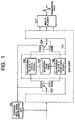
- Fig. 1 is a block diagram showing a configuration of a voice encoder of a first example of the present invention.
- Fig. 1 includes an encoder 101 for compressively encoding voice signals efficiently based on a given algorithm, a voice/non-voice signal identification unit 102 for identifying whether an input signal to the encoder is a voice signal or non-voice signal (such as DTMF signal, PB signal and signalling system No.
- a voice/non-voice signal identification unit 102 for identifying whether an input signal to the encoder is a voice signal or non-voice signal (such as DTMF signal, PB signal and signalling system No.
- switches 103 and 104 as a selector, parameter quantizing blocks 105 and 106 for quantizing certain parameters of the encoder 101, respectively, a quantization table 108 to be referenced at the quantizing blocks, and a multiplexer portion 107 for multiplexing parameters quantized in the quantizing blocks 105 and 106 and other quantized parameter encoded in the encoder 101.
- the quantizing block 105 is the first quantizing block, which is arranged to perform suitable quantization on voice signals.
- the quantizing block 106 is the second quantizing block, which is arranged to perform suitable quantization on non-voice signals (such as DTMF signals).
- the quantizing blocks 105 and 106 differ in determination criteria for determining "suitable" one during the quantization table searches.
- the quantization table 108 to be referenced by the quantizing blocks 105 and 106 when performing quantization must be identical.
- code words (such as quantization index) allocated to quantize values must be common between the quantizing blocks 105 and 106.
- the voice/non-voice signal identification unit 102 always monitors whether an input signal is a voice signal or a non-voice signal and determines an operation mode of the encoder 101 based on the determination result. If the voice/non-voice signal identification unit 102 determines it as "voice”, the switches 103 and 104 are turned to 103A and 104A sides, respectively. As a result, within the encoder 101, a coding processing function block 105 is selected so as to achieve an operation mode suitable for coding a voice signal efficiently ("voice mode" hereinafter). Under this mode, the encoder 101 performs coding processing on the voice signal based on a coding algorithm and outputs a code corresponding to the input voice.
- voice mode an operation mode suitable for coding a voice signal efficiently
- the voice/non-voice signal identification unit 102 determines it as "non-voice”
- the switches 103 and 104 are turned to 103B and 104B sides, respectively.
- the coding processing function block 106 is selected so as to achieve an operation mode suitable for compressively coding the non-voice signal, such as DTMF signal, with less distortion ("non-voice mode" hereinafter).
- the encoder 101 performs coding processing on the non-voice signal, such as DTMF signal, based on a coding algorithm and outputs a code corresponding to the input non-voice signal.
- a DTMF signal includes a dual tone, and a frequency component of an output signal is fixed to a specific value based on the regulation. Accordingly, methods below are used for extracting a characteristic amount on a frequency number:
- the voice/non-voice signal identification unit 102 uses an input signal to calculate the parameter independently. Then, it can determine and output the result based on it.
- the multiplexer portion 107 multiplexes the quantized parameter obtained in the 105 or 106 and another quantized parameter obtained in another processing block in the encoder 101 and required for voice coding, which is sent to the transmission side via the transmission line.
- the identification result output from the voice/DTMF signal identification unit 102 uses common quantization table 108 and code words corresponding to the quantized value.
- the identification result is no longer required information for decoding. Accordingly, it does not have to be sent to the receiver side. Therefore, a bit sequence (frame sequence) sent from the multiplexer portion 107 can be the same format used by the conventional encoder.
- the receiver side can perform decoding by using the exactly same configuration as that of the conventional decoder.
- coding is performed based on a method using a general voice coding algorithm more suitable for voice coding during voice signal transmission, or by switching a part of processing function block into a quantization method more suitable for non-voice signal coding during non-voice signal, especially DTMF signal, transmission. Therefore, a common bit sequence is used between voice transmission and non-voice transmission so that the non-voice signal can be transmitted in more suitable manner.
- a part of functions of coding processing is changed but nothing related to the essential part of a given algorithm is switched.
- the voice/non-voice signal identification unit 102 misidentifies a voice signal input as "non-voice", for example, a certain level of voice transmission quality can be maintained with some deterioration.
- it can prevent the problem that a noisy sound during call is also decoded.
- FIG. 2 A second example according to the present invention will be described with reference to Fig. 2 as follows: This example describes on operation example in detail where a line spectral pair (LSP) quantizer potion is applied to the quantizing blocks 105 and 106 of the example 1.
- LSP line spectral pair
- CS-ACELP method ITU-T Recommendation G. 729 compliant
- FIG. 2 includes LSP quantizing blocks 3A and 3B for performing LSP quantization.
- the LSP quantizing block 3A is a quantizer optimized for quantization of an LSP parameter of a voice signal (voice LSP quantizer, hereinafter) while the LSP quantizing block 3B is a quantizer optimized for quantization of an LSP parameter of DTMF (DTMF LSP quantizer hereinafter).
- voice LSP quantizer hereinafter
- DTMF LSP quantizer a quantizer optimized for quantization of an LSP parameter of DTMF
- LSP line spectral pair
- the LSP method is adopted as a transmission method of the voice spectral envelope information parameter.
- LSP is described in detail in "Line Spectral Pair (LSP) Onsei Bunseki Gousei Houshiki niyoru Onsei Jouhou Assyuku,” Sugemura and Itakura, Denshi Tsushin Gakkai Ronbunshi '81/08 Vol. J64-A, No. 8, pp.599-606.
- LSP Line Spectral Pair
- the voice/non-voice signal identification unit 102 always monitors whether an input signal is a voice signal or a non-voice signal and determines states of the switches 103 and 104 based on the determination result. If the voice/non-voice signal identification unit 102 determines it as "voice”, switches 103 and 104 are turned to 103A and 104A sides, respectively. As a result, the voice LSP quantizer 3A is selected as a quantizing block to set the voice mode. If the voice/non-voice signal identification unit 102 determines it as "non-voice”, switches 103 and 104 are turned to 103B and 104B sides, respectively. As a result, the DTMF LSP quantizer 3B is selected as a quantizing block to set the non-voice mode.
- the voice LSP quantizer 3A has the exactly same as that in Fig. 11. That is, it includes:
- the quantizer 3A quantizes LSP that is a parameter of a frequency region by using a least square error as a determination criteria. That is, selected as a suitable quantized value is a value with a least square error. therefore, the quantization error can be often reflected on a voice signal decoded as a frequency distortion.
- the human ear can detect the spectral distortion of voice in long term as annoying voice. Thus, even if the frequency distortion is increased instantly in accordance with a given state of the MA prediction unit 308, it is not detected as distortion in most of time.
- the DTMF receiving regulation is strict on slight changes in a spectral peak (For example, according to TTC Standard JJ-20.12 "PBX-TDM Digital Interface (channel associated signalling)-PBX-PBX Signal Regulation" PB signal receiving regulation, a frequency divination from the signal frequency specified in the PB sending regulation is specified as within ⁇ 1.8 %. Thus, originally, it is weak to the spectral distortion.
- some structures of the DTMF detector used in an exchange might capture the DTMF instant spectral as a sample for detection. If a DTMF signal encoded and decoded efficiently by using the LSP quantizer 309A is captured as a sample in a time zone where its spectral distortion is increased instantly in accordance to a state of the MA prediction unit 308, it is influenced by the LSP quantization error to the maximum extent. Thus, the signal may not be identified as the DTMF signal. Therefore, frequency distortion in the DTMF transmission needs more attentions than those in voice transmission.
- Some commercially available DTMF detectors identify between voice and DTMF and therefore use a method for detecting high frequency peaks such as the third formant. However, it is not for strict detection in comparison with detection of frequency components of a main signal. Therefore, the components other than frequency components composing DTMF may not cause deterioration of DTMF transmission characteristics even though it is not strict on distortion. that is, in order to decode a DTMF signal without distortion. it is important to minimize the quantization error in frequency range its spectral peak. In the frequency range, which is not related to the other DTMF detection, quantization errors to some extent can be tolerated. According to the trade-off relationship, the DTMF quantizer 309B arranged so that an increase in quantization error for the other frequency components is accepted and the quantization error near the frequency component composing the DTMF is minimized, for example.
- the spectral distortion due to quantization is arranged to be minimized in the vicinity of the tone frequency, which is critical for the DTMF detection. As a result, it can produce effect that a DTMF signal, which is faithful to an original signal can be decoded.
- a quantization error weighting coefficient calculator portion 338 that is a function block within the LSP quantizing block 309 in the second example, is arranged to be able to switch adaptively between voice input and DTMF input based on a determination result by the voice/DTMF signal identification unit 102.
- Fig. 3 includes a voice weighting coefficient calculator portion 338A, which is arranged to be able to evaluate a quantization error of a voice signal LSP coefficient suitably and a DTMF weighting coefficient calculator portion 338B, which is arranged to be able to evaluate a quantization error of a DTMF LSP coefficient suitably.
- a weighting coefficient used for quantization error calculation is calculated based on a method described in equations (1) below according to CS-ACELP method.
- ⁇ i is i-th LSP coefficient.
- a weighting coefficient is weighted for a frequency range with a spectral peak while the weighting coefficient is lightened for a frequency range with spectral "valley.” That is, weights equal to an amount related to the quantization error are allocated for the frequency range with spectral peak, which sharpens the sensitivity for errors.
- LSP with a higher order of weighting coefficient may correspond to a tone frequency. Increasing the weighting coefficient corresponding to the tone frequency component allows the reduction of frequency distortion due to the quantization result locally.
- the same processing as that of the weighting calculator portion 338A is performed and, if the coefficient exceeds a certain threshold, the weighting coefficient may be multiplied by a correction value of 1 or above.
- the threshold and the correction value are desirably obtained by calculating suitable values experimentally in consideration of DTMF recognition ration on the receiver side and deterioration in voice quality due to mis-detection by the voice/DTMF signal identification unit 102, for example.
- the LSP quantization is arranged such that an evaluation criteria for the quantization error is changed in the vicinity of the dual tone frequency composing the DTMF signal, which minimizing spectral distortion in coding. Therefore, the DTMF signal more faithful to an original signal can be decoded.
- a fourth example according to the present invention will be described with reference to Fig. 4.
- the DTMF weighting coefficient calculating portion 338B is replaced by a weighting coefficient memory 338C.
- LSP coefficients of DTMF signals show that a spectral peak corresponding to a lower frequency relates to first to third order of LSP coefficients (especially first and second orders of LSP coefficients contribute largely among them). Further, it is understood that fourth to sixth orders of LSP coefficients relate to higher frequencies (again, fifth and sixth orders of LSP coefficients contribute largely). The other LSP coefficients do not relate to DTMF signal spectral envelop expression in most cases.
- a weighting progression allocating larger weights on first to sixth orders of LSP coefficients and extremely smaller weights on seventh to 10th orders of LSP coefficients is stored which is specified in some manner in advance. When the determination results by the voice/DTMF signal identification unit indicates "DTMF", a least square error is searched by using a weighting coefficient within the memory without calculating it based on pre-quantized LSP coefficients.
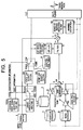
- a digit detection function 102A is added to the voice/DTMF signal identification unit 102 of the example 2 and further a function for loading based on its digit detection result an appropriate LSP coefficient from a memory 111 where LSP coefficients are stored in advance.
- a value of DTMF digit detected in the signal identification unit 102A is sent to the memory 111.
- LSP coefficients corresponding to digits, respectively are stored.
- An appropriate LSP coefficient is extracted therefrom based on an output from the signal identification unit 102A and send it to the LSP quantizer portion.
- the LSP coefficients stored in the memory are produced in an ideal DTMF waveform in advance.
- the DTMF LSP quantizer portion 3B is searched for a quantizing code book based on the ideal LSP coefficients loaded from the memory and outputs index therefore.
- the sixth example according to the present invention will be described with reference to Fig. 6.
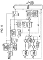
- a so-called closed loop searching method is applied for searching an LSP codebook when DTMF is detection in the LSP quantizer portion 3B of the second example.
- switches 103 and 104 by the signal identification unit 102 are the same as that in the second example.
- an LSP coefficient is quantized first of all based on an input signal to determine a coefficient of the synthesis filter.
- voice signals are merged by combining a adaptive code book index 6A, a noise code book index 6B and a drive signal gain code book index 6C differently and a combination of indices is determined such that a square error with the input voice signal is minimized.
- the coefficient of the synthesis filter is not determined first but a synthesis voice waveform to be decoded in the decoder is evaluated in the same manner as other three kinds of quantization parameters.
- the adaptive codebook index 6A, noise code book index 6B and drive signal gain code book index 6c which are quantization parameters to be transmitter to the decoder, are synthesized to generate plural patterns of excitation signal 6E candidates of the synthesis filter.
- plural patterns of LSP coefficients stored in the LSP codebook is used for generating a composite signal in the filter 6.
- a least square error searching portion 17 square errors are calculated of the plural kinds of synthesized signals obtained as above and a voice signal 6F input to the encoder. Then, a combination of quantization parameters is selected such that the square error is the least among them. Each parameter is encoded and multiplexed in the multiplexer potion 107, which is transmitted to the decoder.
- voice is merged for all four kinds of combinations of the LSP codebook index 6D. Then, a square error between the input signal and the composite signal is calculated for each composite signal waveform to search the quantization parameter combination with the least square error. Therefore, DTMF signals with less waveform distortion can be decoded.
- a plurality of quantization LSP coefficient candidate obtained from combination of three kinds of LSP code books 335 to 337 and MA prediction is supplied to a synthesis filter 340 configured locally in the DTMF LSP quantizer 3B.
- the residual signal 7A generated in the filter is input into the filter in order to obtain a plurality of signals corresponding to respective LSP coefficient candidate.
- a square error between the plurality of composite signals and voice signals input into the encoder is calculated, and then combination of LSP parameters with the least square error is searched. Then, its index is extracted and output.
- voice is merger with respect to all of quantization parameters, and a square error between each composite signal waveform and an input signal is calculated for evaluation.
- a square error between each composite signal waveform and an input signal is calculated for evaluation.
- coding and decoding are performed based on a method using a general voice coding/decoding algorithms more suitable for coding voices during voice signal transmission, or by switching a part of processing function block into a method more suitable for coding non-voice signals during non-voice signal, especially DTMF signal, transmission.
- high quality non-voice signals can be transmitted at the time of non-voice signal transmission without changing the transmission bit-rate.
- the voice/non-voice signal identification unit 102 misidentifies a voice signal input as "non-voice", for example, a certain level of voice transmission quality can be maintained with some deterioration.
- it can prevent the problem that a noisy sound during call is also decoded.
- the simple device configuration can reduce manufacturing costs, advantageously.
Landscapes
- Engineering & Computer Science (AREA)
- Theoretical Computer Science (AREA)
- Computational Linguistics (AREA)
- Signal Processing (AREA)
- Health & Medical Sciences (AREA)
- Audiology, Speech & Language Pathology (AREA)
- Human Computer Interaction (AREA)
- Physics & Mathematics (AREA)
- Acoustics & Sound (AREA)
- Multimedia (AREA)
- Compression, Expansion, Code Conversion, And Decoders (AREA)
- Use Of Switch Circuits For Exchanges And Methods Of Control Of Multiplex Exchanges (AREA)
- Telephonic Communication Services (AREA)
Abstract
A voice encoding device according to the present invention includes an encoder having a first quantizing block suitable for voice encoding and a second quantizing block suitable for non-voice encoding and compressively encoding input signals, a voice/non-voice signal identification unit for identifying whether an signal input to the encoder is a voice signal or a non-voice signal and outputting a determination result, and a multiplexer portion for multiplexing respective outputs from the first quantizing block and the second quantizing block in order to output to a transmission path. In this case, the encoder has a selector for selecting either one of the first quantizing block or the second quantizing in accordance with the determination result from the voice/non-voice signal identification unit, and the first quantizing block and the second quantizing block compressively encode signals by using a same quantization table. <IMAGE>
Description
The present invention relates to an voice encoder used
in voice digital wired communication and radio communication,
in particular to a method for improving an voice encoder for
transmitting non-voice signal using an voice frequency band,
such as dual tone multi frequency, DTMF, signals and push
button, PB, signals.
The reduction of communication cost is the most
important issue in the private network. In order to achieve
highly efficient transmission of voice signals occupying
most part of communication traffics, cases where highly
efficient voice encoder based on voice encoding and decoding
is applied is increasing, which is exemplified by 8 kbit/s
conjugate-structure algebraic-code-excited linear prediction,
CS-ACELP, voice encoding method (ITU-T Recommendation G. 729
compliant).
The voice encoding algorithm where the transmission
speed is 8 kbit/s has a structure where input signals are
specific to voice signals in order to obtain high quality
voice with less information amount. This will be described
with reference to the 8 kbit/s CS-ACELP system. Fig. 9
shows a schematic block diagram of an encoder, and Fig. 10
shows a detail block diagram of the encoder.
This encoding method has an encoding algorithm where
the human vocalizing mechanism is modeled. In other words,
it is based on CELP method, which uses a composite filter 6
(linear filter corresponding to voice spectral envelops)
where human vocal tract information is modeled to drive time
series signals (outputs of an adder 15) stored in a code
book corresponding to the human vocal cords information.
The detail description of the algorithm can be found in
ITU-T Recommendation G. 729, "Coding of Speech at 8 kbit/s
using Conjugate-Structure Algebraic-Code-Excited Linear
Prediction (CS-ACELP)".
In the coding algorithm specific to voices, higher
efficient transmission tends to deteriorate transmission
characteristics of signals (such as DTMF signals, PB signals,
No. 5 signaling, modem signals) other than voice signals
using the voice frequency band in a transmission path using
the highly efficient voice encoder.
Of one example showing the condition, details of LSP
quantizer portion will be described with reference to FIG.
11. FIG. 11 shows an LSP quantifier portion (309) within an
encoder based on the CS-ACELP method shown in FIG. 9. FIG.
11 includes an MA prediction component calculator 308 for
calculating Moving Average (MA) of an LSP, a multiplier 330,
adders 331, 332, and 333, a quantized error weighting
coefficient calculator portion 338 for calculating a
weighting coefficient based on an input LSP coefficient, a
least square error calculator 334 for calculating a square
error between a quantized LSP vector calculated in the adder
332 and an LSP vector calculated based on an input voice
signals and multiplying it by the weighting coefficient
calculated in 334 to select a least square error among
quantifier LSP vector candidates, the first stage LSP
codebook 335, the second stage LSP codebook 336, and an MA
prediction coefficient codebook 337 where a plurality kinds
of sets of MA coefficients.
Since the LSP quantization method using this structure
is described in detail in "CS-ACELP no LSP to gain no
ryoushikahou", Kataoka et al., NTT R&D, Vol. 45 No. 4, 1996,
pp. 331-336. Thus, the description is omitted here. It is
known that the LSP quantization method is used so that voice
signal spectral envelop information can be quantized
efficiently.
According to the CS-ACELP voice coding method, the
quantization of LSP coefficients is achieved by following
three processes. That is, the LSP quantizer portion 309 has
three processing function blocks as shown below:
The MA (Moving Average) in (1) is used so that signals
with few radical changes in frequency characteristics, that
is, having strong correlation between frames can be
quantized efficiently. Further, the learned codebook of (2)
is used so that a schematic form of a spectral envelope
specific to audio signals can be expressed efficiently with
a few information amounts. Furthermore, when the random
code book of (3) is used in addition to the learned code
book of (2) so that slight changes in spectral envelop can
be followed flexibly. In consideration of the above-described
reasons, it can be said that the LSP quantifier
portion 309 is a well suitable method for coding
characteristics of voice spectral envelope information
efficiently. On the other hand, in order to code non-voice
signals, especially DTMF signals, characteristics as
described below must be considered:
- Voice signals and DTMF signals differ significantly in spectral envelope;
- radical changes in spectral characteristics are found between a signal continue time and a pause time. Gains also changes radically. However, a change amount in spectral characteristics and gains only for the duration of DTMF signals is extremely small;
- Since quantization distortion of LSP is reflected on frequency distortion of DTMF as it is, the LSP quantization distortion must be small as much as possible; and
- For the duration of the DTMF signals, the frequency characteristic is extremely stable.
In consideration of the above-described viewpoints, it
cannot be said that the LSP quantizer portion 309 is an
effective method for coding the spectral envelope of DTMF
signals.
As described in the example above, the non-voice
signals such as DTMF signals have different characteristics
from those of voice signals in several viewpoints. Thus,
when the non-voice signals are coded, it is not suitable to
use a same method as one used for voice signals under the
condition where the transmission bit rate is low and
redundancy for coding is small.
By the way, in the private network, for the call set-up
in the telephone communication, the in-channel signalling is
performed by using DTMF signals instead of the common
channel signalling. In this case, if an allocated
transmission path uses the voice coding, it deteriorates
transmission characteristics of the DTMF signals. As a
result, the call set-up frequently cannot be achieved
normally.
As the first solution for overcoming the problem, a
device configuration in FIG. 12 as disclosed in Japanese
Unexamined Patent Application Publication No. 9-81199 may be
adopted. This configuration includes a unit for identifying
a voice signal and a non-voice signal such as a DTMF signal
on the transmission side and memories for storing patterns
in which the DTMF signal is pre-decoded on the transmission
side and a receiver side. When the identification unit
identified a DTMF signal input, an index of a memory holding
the coded patterns corresponding to a number of DTMF to the
receiver side, where the index was identified to generate a
DTMF signal corresponding to the digit.
As the second solution for overcoming the problem, a
device configuration in FIG. 13 may be adopted, for example.
An encoder 101 includes one which is optimized for coding
voice signals and one which is optimized for compressively
coding non-voice signals (such as DTMF signal) with less
distortion. The configuration includes a unit for
identifying whether a signal to be transmitted is voice or
non-voice and selecting one of the function blocks based on
the determination result from the identification unit for
coding processing. Further, the configuration includes a
unit for folding the determination result into an encoder
output so that transmission can be achieved without changing
its transmission bit-rate and with least deterioration in
voice quality. Furthermore, a searching unit corresponding
to the encoder 101 is provided on a side of a decoder 201
also.
Next, operations of the voice coding and decoders will
be described. On the transmission side in FIG. 13, a
voice/non-voice signal identification unit 102 always
monitors whether an input signal is a voice signal or a non-voice
signal and determines an operation mode of the encoder
101 based on the determination result. If the voice/non-voice
signal identification unit 102 determines it as
"voice", switches 103 and 14 are turned to 103A and 104A
sides, respectively. As a result, within the encoder 101, a
coding processing function block 105 is selected so as to
achieve an operation mode suitable for coding a voice signal
efficiently ("voice mode" hereinafter).
Under this mode, the encoder 101 performs coding
processing on the voice signal based on a coding algorithm
and outputs a code corresponding to the input voice. On the
other hand, if the voice/non-voice signal identification
unit 102 determines it as "non-voice", the switches 103 and
14 are turned to 103B and 104B sides, respectively. As a
result, within the encoder 101, the coding processing
function block 106 is selected so as to achieve an operation
mode suitable for compressively coding the non-voice signal,
such as DTMF signal, with less distortion ("non-voice mode"
hereinafter).
Under this mode, the encoder 101 performs coding
processing on the non-voice signal, such as DTMF signal,
based on a coding algorithm and outputs a code corresponding
to the input non-voice signal. Further, a multiplexer
portion 107 multiplexes one obtained by coding a voice
signal or a non-voice signal (voice/non-voice code,
hereinafter) and a result from identification of an input
signal(voice signal or non-voice signal), which is output
from the voice/non-voice signal identification unit 102 and
send it to the transmission path.
On the receiver side in FIG. 13, first of all, the bit
sequence received from the transmission path is separated
into voice/non-voice codes and a determination result of the
voice/non-voice identification unit 102 in a demultiplexer
portion 202. If the determination results by the voice/non-voice
signal identification unit 102 taken out of the signal
array is "voice", switches 203 and 204 are turned to 203A
and 204A sides, respectively. As a result, within the
decoder 201, a decoding processing function block 205 is
selected, which achieves in the decoder an operation mode
corresponding to the voice mode in the encoder 101. Under
this mode, the decoder 201 performs decoding processing
based on a decoding algorithm in order to decode the voice
signals. Here, since both encoding and decoding are
performed under the voice mode, the decoded voice signals
have quality in accordance with the original performance the
coding algorithm has.
If the determination results by the voice/non-voice
signal identification unit 102 taken out of the signal array
in the demultiplexer portion 202 is "non-voice", switches
203 and 204 are turned to 203B and 204B sides, respectively.
As a result, within the decoder 201, a decoding processing
function block 206 is selected, which achieves in the
decoder an operation mode corresponding to the non-voice
mode in the encoder 101. Under this mode, the decoder 201
performs decoding processing based on a decoding algorithm
in order to decode the non-voice signals. Here, since both
encoding and decoding are performed under the non-voice mode,
the decoded non-voice signals have even less distortion than
those performed under the voice mode.
According to the conventional embodiment as described
above, coding and decoding are performed based on a method
using a general voice coding/decoding algorithms more
suitable for coding voices during voice signal transmission,
or by switching a part of processing function block into a
method more suitable for coding non-voice signals during
non-voice signal, especially DTMF signal, transmission.
Thus, during the non-voice signal transmission, high quality
non-voice signals can be transmitted without an increase in
transmission bit rate.
When a voice communication system based on the
conventional example is established, it is required to have
the non-voice mode in both encoder 101 and decoder 201.
Only improvement in the transmission side (coding side)
cannot allow the decoder side to address the non-voice mode.
As a result, nothing can decode normal voice signals, which
may cause undesirable phenomena for a caller, such
occurrence of noises.
By the way, when enterprise communication system is
established, for example, voice transmission equipments
cannot be replaced concurrently on sender and receiver sides
for various reasons. For example, it is assumed that a
voice transmission device (such as multimedia multiplexer
equipments) are established which have voice encoder and
decode based on the CS-ACELP method conforming to
conventional ITU-T Recommendation G. 729. In this case,
even if the voice transmission device addressing the non-voice
mode is replaced only the transmission side for the
purpose of achieving DTMF in-channel transmission, mutual
connections cannot be performed because the voice
transmission device on the receiver side is still a
conventional decoder. Thus, the voice transmission device
must be replaced. However, it requires further expensive
investment for the user of the voice transmission device,
which makes the replacement difficult.
The present invention was made for overcoming the
conventional problems. It is an object of the present
invention to provide a voice encoder for the improvement of
transmission characteristics of non-voice signals such as
DTMF signals by permitting mutual connections with a
conventional decode and in-channel transmission of non-voice
signals such as DTMF signals when highly efficient voice
encoder and decoder are provided which maintain voice
transmission quality a given coding algorithm originally has.
A voice encoding device according to the present
invention includes an encoder having a first quantizing
block suitable for voice encoding and a second quantizing
block suitable for non-voice encoding and compressively
encoding input signals, a voice/non-voice signal
identification unit for identifying whether an input signal
to the encoder is a voice signal or a non-voice signal and
outputting a determination result, and a multiplexer portion
for multiplexing respective outputs from the first
quantizing block and the second quantizing block in order to
output to a transmission path. In this case, the encoder
has a selector for selecting either one of the first
quantizing block or the second quantizing in accordance with
the determination result from the voice/non-voice signal
identification unit, and the first quantizing block and the
second quantizing block compressively encode signals by
using a same quantization table.
The first and second quantizing blocks are processing
blocks for quantizing a line spectral pair (LSP) coefficient.
When the LSP coefficient is quantized, the first and
second coefficient quantizing blocks have a different
evaluation criteria to be used for determining an
appropriate quantized value from each other.
Further, when the LSP coefficient is quantized, the
evaluation criteria used for determining an appropriate
quantized value is changed adaptively in accordance with a
characteristic of an input voice signal in the first
quantizing block, while the evaluation criteria is steady
regardless of a characteristic of an input voice signal in
the second quantizing block.
Also, the voice/non-voice signal identification unit
has digit detector for detecting a digit of a DTMF signal;
and inputs an LSP coefficient to the second quantizing block.
The voice/non-voice signal identification unit uses a
closed loop searching method as a method for searching an
LSP codebook.
The second quantizing block uses a linear prediction
residual signal of an input voice signal as a parameter used
for determining an appropriate quantized value.
One example of the present invention will be described
with reference to a drawing as follows:
Fig. 1 is a block diagram showing a configuration of a
voice encoder of a first example of the present invention.
Fig. 1 includes an encoder 101 for compressively encoding
voice signals efficiently based on a given algorithm, a
voice/non-voice signal identification unit 102 for
identifying whether an input signal to the encoder is a
voice signal or non-voice signal (such as DTMF signal, PB
signal and signalling system No. 5) in order to output a
determination result, switches 103 and 104 as a selector,
parameter quantizing blocks 105 and 106 for quantizing
certain parameters of the encoder 101, respectively, a
quantization table 108 to be referenced at the quantizing
blocks, and a multiplexer portion 107 for multiplexing
parameters quantized in the quantizing blocks 105 and 106
and other quantized parameter encoded in the encoder 101.
Here, the quantizing block 105 is the first quantizing
block, which is arranged to perform suitable quantization on
voice signals. On the other hand, the quantizing block 106
is the second quantizing block, which is arranged to perform
suitable quantization on non-voice signals (such as DTMF
signals). For example, it is assumed that the quantizing
blocks 105 and 106 differ in determination criteria for
determining "suitable" one during the quantization table
searches. In this case, in order to implement this example,
the quantization table 108 to be referenced by the
quantizing blocks 105 and 106 when performing quantization
must be identical. Also, code words (such as quantization
index) allocated to quantize values must be common between
the quantizing blocks 105 and 106.
Next, operations of the voice encoder will be described.
In Fig. 1, the voice/non-voice signal identification unit
102 always monitors whether an input signal is a voice
signal or a non-voice signal and determines an operation
mode of the encoder 101 based on the determination result.
If the voice/non-voice signal identification unit 102
determines it as "voice", the switches 103 and 104 are
turned to 103A and 104A sides, respectively. As a result,
within the encoder 101, a coding processing function block
105 is selected so as to achieve an operation mode suitable
for coding a voice signal efficiently ("voice mode"
hereinafter). Under this mode, the encoder 101 performs
coding processing on the voice signal based on a coding
algorithm and outputs a code corresponding to the input
voice.
On the other hand, if the voice/non-voice signal
identification unit 102 determines it as "non-voice", the
switches 103 and 104 are turned to 103B and 104B sides,
respectively. As a result, within the encoder 101, the
coding processing function block 106 is selected so as to
achieve an operation mode suitable for compressively coding
the non-voice signal, such as DTMF signal, with less
distortion ("non-voice mode" hereinafter). Under this mode,
the encoder 101 performs coding processing on the non-voice
signal, such as DTMF signal, based on a coding algorithm and
outputs a code corresponding to the input non-voice signal.
An operation of the voice/non-voice identification unit
102 will be described by using a DTMF signal as one example
of a non-voice signal to be identified. A DTMF signal
includes a dual tone, and a frequency component of an output
signal is fixed to a specific value based on the regulation.
Accordingly, methods below are used for extracting a
characteristic amount on a frequency number:
- FFT is used for frequency analysis; or
- a band pass filter is used for filtering a specific frequency component. Then, it is determined whether or not the characteristic amount matches to the characteristic amount of the DTMF signal for identification.
Since the transmission level of the DTMF signal is
limited to a specific range according to the regulation and
has small dynamic range, the characteristics of the DTMF
signal is significantly different from the voice signal,
which has relatively a wider dynamic range. Therefore, the
input signal level is monitored and it is used as auxiliary
information for DTMF signal identification. Thus, it allows
enhancing accuracy of detecting DTMF signals. The
voice/non-voice signal identification unit 102 uses an input
signal to calculate the parameter independently. Then, it
can determine and output the result based on it.
The multiplexer portion 107 multiplexes the quantized
parameter obtained in the 105 or 106 and another quantized
parameter obtained in another processing block in the
encoder 101 and required for voice coding, which is sent to
the transmission side via the transmission line. Here, the
identification result output from the voice/DTMF signal
identification unit 102 uses common quantization table 108
and code words corresponding to the quantized value. Thus,
the identification result is no longer required information
for decoding. Accordingly, it does not have to be sent to
the receiver side. Therefore, a bit sequence (frame
sequence) sent from the multiplexer portion 107 can be the
same format used by the conventional encoder.
Since the bit sequence sent from the transmission side
is exactly the same as conventional one and physical
characteristics of a parameter for expressing a code word is
also in common with the conventional encoder. Therefore,
the receiver side can perform decoding by using the exactly
same configuration as that of the conventional decoder.
As described above, according to this example, coding
is performed based on a method using a general voice coding
algorithm more suitable for voice coding during voice signal
transmission, or by switching a part of processing function
block into a quantization method more suitable for non-voice
signal coding during non-voice signal, especially DTMF
signal, transmission. Therefore, a common bit sequence is
used between voice transmission and non-voice transmission
so that the non-voice signal can be transmitted in more
suitable manner.
Further, in this example, a part of functions of coding
processing is changed but nothing related to the essential
part of a given algorithm is switched. Thus, when the
voice/non-voice signal identification unit 102 misidentifies
a voice signal input as "non-voice", for example, a certain
level of voice transmission quality can be maintained with
some deterioration. Advantageously, it can prevent the
problem that a noisy sound during call is also decoded.
A second example according to the present invention
will be described with reference to Fig. 2 as follows: This
example describes on operation example in detail where a
line spectral pair (LSP) quantizer potion is applied to the
quantizing blocks 105 and 106 of the example 1. For simple
description, it is assumed that CS-ACELP method (ITU-T
Recommendation G. 729 compliant) is used as one example of
the coding algorithm. A detail block diagram of the encoder
based on the CS-ACELP method is as shown in Fig. 9. Fig. 2
includes LSP quantizing blocks 3A and 3B for performing LSP
quantization. The LSP quantizing block 3A is a quantizer
optimized for quantization of an LSP parameter of a voice
signal (voice LSP quantizer, hereinafter) while the LSP
quantizing block 3B is a quantizer optimized for
quantization of an LSP parameter of DTMF (DTMF LSP quantizer
hereinafter). Elements having the same reference numbers as
those in Figures. 1, 9, and 10 have the same functions as
those described in EXAMPLE 1. Thus, description therefor is
omitted here.
In an encoder for encoding voices efficiently, a line
spectral pair (LSP) is often used as a method for expressing
voice signal spectral envelope information efficiently.
Thus, in the CS-ACELP method, the LSP method is adopted as a
transmission method of the voice spectral envelope
information parameter. LSP is described in detail in "Line
Spectral Pair (LSP) Onsei Bunseki Gousei Houshiki niyoru
Onsei Jouhou Assyuku," Sugemura and Itakura, Denshi Tsushin
Gakkai Ronbunshi '81/08 Vol. J64-A, No. 8, pp.599-606. Thus,
the description therefor is omitted here.
Next, operations of the encoder will be described. In
FIG. 2, the voice/non-voice signal identification unit 102
always monitors whether an input signal is a voice signal or
a non-voice signal and determines states of the switches 103
and 104 based on the determination result. If the
voice/non-voice signal identification unit 102 determines it
as "voice", switches 103 and 104 are turned to 103A and 104A
sides, respectively. As a result, the voice LSP quantizer
3A is selected as a quantizing block to set the voice mode.
If the voice/non-voice signal identification unit 102
determines it as "non-voice", switches 103 and 104 are
turned to 103B and 104B sides, respectively. As a result,
the DTMF LSP quantizer 3B is selected as a quantizing block
to set the non-voice mode.
The voice LSP quantizer 3A has the exactly same as that
in Fig. 11. That is, it includes:
It also uses two methods of inter-frame prediction and multi-level quantization.
The quantizer 3A quantizes LSP that is a parameter of a
frequency region by using a least square error as a
determination criteria. That is, selected as a suitable
quantized value is a value with a least square error.
therefore, the quantization error can be often reflected on
a voice signal decoded as a frequency distortion.
The human ear can detect the spectral distortion of
voice in long term as annoying voice. Thus, even if the
frequency distortion is increased instantly in accordance
with a given state of the MA prediction unit 308, it is not
detected as distortion in most of time. However, the DTMF
receiving regulation is strict on slight changes in a
spectral peak (For example, according to TTC Standard JJ-20.12
"PBX-TDM Digital Interface (channel associated
signalling)-PBX-PBX Signal Regulation" PB signal receiving
regulation, a frequency divination from the signal frequency
specified in the PB sending regulation is specified as
within ±1.8 %. Thus, originally, it is weak to the spectral
distortion.
Further, some structures of the DTMF detector used in
an exchange, for example, might capture the DTMF instant
spectral as a sample for detection. If a DTMF signal encoded
and decoded efficiently by using the LSP quantizer 309A is
captured as a sample in a time zone where its spectral
distortion is increased instantly in accordance to a state
of the MA prediction unit 308, it is influenced by the LSP
quantization error to the maximum extent. Thus, the signal
may not be identified as the DTMF signal. Therefore,
frequency distortion in the DTMF transmission needs more
attentions than those in voice transmission.
Some commercially available DTMF detectors identify
between voice and DTMF and therefore use a method for
detecting high frequency peaks such as the third formant.
However, it is not for strict detection in comparison with
detection of frequency components of a main signal.
Therefore, the components other than frequency components
composing DTMF may not cause deterioration of DTMF
transmission characteristics even though it is not strict on
distortion. that is, in order to decode a DTMF signal
without distortion. it is important to minimize the
quantization error in frequency range its spectral peak. In
the frequency range, which is not related to the other DTMF
detection, quantization errors to some extent can be
tolerated. According to the trade-off relationship, the
DTMF quantizer 309B arranged so that an increase in
quantization error for the other frequency components is
accepted and the quantization error near the frequency
component composing the DTMF is minimized, for example.
As described above, the spectral distortion due to
quantization is arranged to be minimized in the vicinity of
the tone frequency, which is critical for the DTMF detection.
As a result, it can produce effect that a DTMF signal, which
is faithful to an original signal can be decoded.
the third example according to the present invention
will be described with reference to Fig. 3 as follows: In
this example, a quantization error weighting coefficient
calculator portion 338, that is a function block within the
LSP quantizing block 309 in the second example, is arranged
to be able to switch adaptively between voice input and DTMF
input based on a determination result by the voice/DTMF
signal identification unit 102. Fig. 3 includes a voice
weighting coefficient calculator portion 338A, which is
arranged to be able to evaluate a quantization error of a
voice signal LSP coefficient suitably and a DTMF weighting
coefficient calculator portion 338B, which is arranged to be
able to evaluate a quantization error of a DTMF LSP
coefficient suitably.
Next, an operation will be described. In this example,
a weighting coefficient used for quantization error
calculation is calculated based on a method described in
equations (1) below according to CS-ACELP method.
 where ωi is i-th LSP coefficient.
That is, a weighting coefficient is weighted for a
frequency range with a spectral peak while the weighting
coefficient is lightened for a frequency range with
spectral "valley." That is, weights equal to an amount
related to the quantization error are allocated for the
frequency range with spectral peak, which sharpens the
sensitivity for errors. Here, when a DTMF signal is LSP-encoded,
LSP with a higher order of weighting coefficient
may correspond to a tone frequency. Increasing the
weighting coefficient corresponding to the tone frequency
component allows the reduction of frequency distortion due
to the quantization result locally.
In order to increase the weighting coefficient of the
LSP coefficient, which might correspond to the DTMF tone
frequency, the same processing as that of the weighting
calculator portion 338A is performed and, if the coefficient
exceeds a certain threshold, the weighting coefficient may
be multiplied by a correction value of 1 or above. For the
threshold and the correction value are desirably obtained by
calculating suitable values experimentally in consideration
of DTMF recognition ration on the receiver side and
deterioration in voice quality due to mis-detection by the
voice/DTMF signal identification unit 102, for example.
As described above, according to the third example of
the present invention, the LSP quantization is arranged such
that an evaluation criteria for the quantization error is
changed in the vicinity of the dual tone frequency composing
the DTMF signal, which minimizing spectral distortion in
coding. Therefore, the DTMF signal more faithful to an
original signal can be decoded.
A fourth example according to the present invention
will be described with reference to Fig. 4. In this example,
the DTMF weighting coefficient calculating portion 338B is
replaced by a weighting coefficient memory 338C.
Studying LSP coefficients of DTMF signals in detail
indicates that a spectral peak corresponding to a lower
frequency relates to first to third order of LSP
coefficients (especially first and second orders of LSP
coefficients contribute largely among them). Further, it is
understood that fourth to sixth orders of LSP coefficients
relate to higher frequencies (again, fifth and sixth orders
of LSP coefficients contribute largely). The other LSP
coefficients do not relate to DTMF signal spectral envelop
expression in most cases. In the memory 338C, a weighting
progression allocating larger weights on first to sixth
orders of LSP coefficients and extremely smaller weights on
seventh to 10th orders of LSP coefficients is stored which
is specified in some manner in advance. When the
determination results by the voice/DTMF signal
identification unit indicates "DTMF", a least square error
is searched by using a weighting coefficient within the
memory without calculating it based on pre-quantized LSP
coefficients.
As described above, according to this example, it is no
longer necessary to have the DTMF weighting coefficient
calculating portion specifically. Therefore, advantageously,
a program capacity for implementing an encoding algorithm
can be reduced and further the encoding algorithm can be
simplified for easier adoption.
The fifth example according to the present invention
will be described with reference to Fig. 5. In this example,
a digit detection function 102A is added to the voice/DTMF
signal identification unit 102 of the example 2 and further
a function for loading based on its digit detection result
an appropriate LSP coefficient from a memory 111 where LSP
coefficients are stored in advance.
Next, an operation will be described, a value of DTMF
digit detected in the signal identification unit 102A is
sent to the memory 111. In the memory 111, LSP coefficients
corresponding to digits, respectively, are stored. An
appropriate LSP coefficient is extracted therefrom based on
an output from the signal identification unit 102A and send
it to the LSP quantizer portion. The LSP coefficients
stored in the memory are produced in an ideal DTMF waveform
in advance. When a DTMF is detected, the DTMF LSP quantizer
portion 3B is searched for a quantizing code book based on
the ideal LSP coefficients loaded from the memory and
outputs index therefore.
Application of this example allows correction of DTMF
signals input to the encoder with twist distortion and/or
some frequency distortion at the time of LSP quantization.
Therefore, the DTMF signal having a desirable characteristic
can be sent.
The sixth example according to the present invention
will be described with reference to Fig. 6. In this example,
a so-called closed loop searching method is applied for
searching an LSP codebook when DTMF is detection in the LSP
quantizer portion 3B of the second example.
Next, an operation will be described. Operations of
switches 103 and 104 by the signal identification unit 102
are the same as that in the second example. While encoding
the human voice, that is, according to the conventional CS-ACELP
method, an LSP coefficient is quantized first of all
based on an input signal to determine a coefficient of the
synthesis filter. Then, voice signals are merged by
combining a adaptive code book index 6A, a noise code book
index 6B and a drive signal gain code book index 6C
differently and a combination of indices is determined such
that a square error with the input voice signal is minimized.
On the other hand, for LSP quantization at the time of
DTMF detection, the coefficient of the synthesis filter is
not determined first but a synthesis voice waveform to be
decoded in the decoder is evaluated in the same manner as
other three kinds of quantization parameters. First of all,
the adaptive codebook index 6A, noise code book index 6B and
drive signal gain code book index 6c, which are quantization
parameters to be transmitter to the decoder, are synthesized
to generate plural patterns of excitation signal 6E
candidates of the synthesis filter. For each of the
excitation signals 6E, plural patterns of LSP coefficients
stored in the LSP codebook is used for generating a
composite signal in the filter 6. In a least square error
searching portion 17, square errors are calculated of the
plural kinds of synthesized signals obtained as above and a
voice signal 6F input to the encoder. Then, a combination
of quantization parameters is selected such that the square
error is the least among them. Each parameter is encoded
and multiplexed in the multiplexer potion 107, which is
transmitted to the decoder.
According to this example, voice is merged for all four
kinds of combinations of the LSP codebook index 6D. Then, a
square error between the input signal and the composite
signal is calculated for each composite signal waveform to
search the quantization parameter combination with the least
square error. Therefore, DTMF signals with less waveform
distortion can be decoded.
The seventh example according to the present invention
will be described with reference to Figures 8 and 9. In
this example, plural kinds of drive signals used for LSP
quantization evaluation in sixth example is replaced by
prediction residual signals of input signals.
Next, an operation will be described. First of all,
operations on switches 103 and 104 are the same as those in
the second example. Linearly prediction analysis is
performed on voice signals input to the encoder in the block
2. At the same time, the voice signals are input into a
inverse-synthesis filter 110 which is configured by using a
linear prediction coefficient obtained therefrom. A linear
prediction residual signal 7A output from the inverse-synthesis
filter 110 is input into the DTMF LSP quantized
for the evaluation at the time of LSP quantization. The
inverse-synthesis filter 110 can be configured by using a
transmission function shown, for example, in an equation (2)
below:
S-1 (z)=1+ i =1 10 αi z -i
wherein αi is a linear prediction coefficient calculated in
the linear prediction analyzer portion 2.
here, an operation of theDTMF LSP quantizer 3B will be
described in detail with reference to Fig. 8. A plurality
of quantization LSP coefficient candidate obtained from
combination of three kinds of LSP code books 335 to 337 and
MA prediction is supplied to a synthesis filter 340
configured locally in the DTMF LSP quantizer 3B. The
residual signal 7A generated in the filter is input into the
filter in order to obtain a plurality of signals
corresponding to respective LSP coefficient candidate. A
square error between the plurality of composite signals and
voice signals input into the encoder is calculated, and then
combination of LSP parameters with the least square error is
searched. Then, its index is extracted and output.
here, an operation of the
In the sixth example, voice is merger with respect to
all of quantization parameters, and a square error between
each composite signal waveform and an input signal is
calculated for evaluation. Thus, while an appropriate
quantization parameter combination can be obtained, its
calculation amount has been enormous. By using this example,
while its performance is decreased to some extent, the
quantization distortion and the amount of calculation are
reduced. Thus, it is effective in that it can be
implemented by using an inexpensive DSP with lower power
consumption, for example.
According to the present invention, coding and decoding
are performed based on a method using a general voice
coding/decoding algorithms more suitable for coding voices
during voice signal transmission, or by switching a part of
processing function block into a method more suitable for
coding non-voice signals during non-voice signal, especially
DTMF signal, transmission. Thus, high quality non-voice
signals can be transmitted at the time of non-voice signal
transmission without changing the transmission bit-rate.
Further, a part of functions of coding/decoding
processing is changed but nothing related to the essential
part of a given algorithm is switched. Thus, when the
voice/non-voice signal identification unit 102 misidentifies
a voice signal input as "non-voice", for example, a certain
level of voice transmission quality can be maintained with
some deterioration. Advantageously, it can prevent the
problem that a noisy sound during call is also decoded.
Furthermore, even when a voice/non-voice signal
identification unit configured based on an easy method and
with lower identification performance is applied, a certain
level of voice quality can be maintained. The simple device
configuration can reduce manufacturing costs, advantageously.
Claims (7)
- A voice encoding device, comprising:an encoder having a first quantizing block suitable for voice encoding and a second quantizing block suitable for non-voice encoding and compressively encoding input signals;a voice/non-voice signal identification unit for identifying whether an signal input to said encoder is a voice signal or a non-voice signal and outputting a determination result; anda multiplexer portion for multiplexing respective outputs from said first quantizing block and said second quantizing block in order to output to a transmission path;
wherein said encoder has selector means for selecting either one of said first quantizing block or said second quantizing block in accordance with said determination result from said voice/non-voice signal identification unit; andsaid first quantizing block and said second quantizing block compressively encode signals by using a same quantization table. - A voice encoding device according to claim 1, wherein said first and second quantizing blocks are processing blocks for quantizing a line spectral pair (LSP) coefficient.
- A voice encoding device according to claim 2, wherein, when said LSP coefficient is quantized, said first and second coefficient quantizing blocks have a different evaluation criteria to be used for determining an appropriate quantized value from each other.
- A voice encoding device according to claim 2, wherein, when said LSP coefficient is quantized, the evaluation criteria used for determining an appropriate quantized value is changed adaptively in accordance with a characteristic of an input voice signal in said first quantizing block;while said evaluation criteria is steady regardless of a characteristic of an input voice signal in said second quantizing block.
- A voice encoding device according to claim 1, said voice/non-voice signal identification unit:having digit detecting means for detecting a digit of a DTMF signal; andinputting an LSP coefficient to said second quantizing block.
- A voice encoding device according to of claim 1, said voice/non-voice signal identification unit using a closed loop searching method as a method for searching an LSP codebook.
- A voice encoding device according to claim 6, said second quantizing block uses a linear prediction residual signal of an input voice signal as a parameter used for determining an appropriate quantized value.
Applications Claiming Priority (3)
| Application Number | Priority Date | Filing Date | Title |
|---|---|---|---|
| JP11112013A JP2000308167A (en) | 1999-04-20 | 1999-04-20 | Audio coding device |
| JP11201399 | 1999-04-20 | ||
| PCT/JP2000/002464 WO2000064055A1 (en) | 1999-04-20 | 2000-04-14 | Voice encoding device |
Publications (2)
| Publication Number | Publication Date |
|---|---|
| EP1091495A1 true EP1091495A1 (en) | 2001-04-11 |
| EP1091495A4 EP1091495A4 (en) | 2005-08-10 |
Family
ID=14575797
Family Applications (1)
| Application Number | Title | Priority Date | Filing Date |
|---|---|---|---|
| EP00915544A Withdrawn EP1091495A4 (en) | 1999-04-20 | 2000-04-14 | DEVICE FOR ENCODING VOICE SIGNALS |
Country Status (5)
| Country | Link |
|---|---|
| US (1) | US6484139B2 (en) |
| EP (1) | EP1091495A4 (en) |
| JP (1) | JP2000308167A (en) |
| IL (1) | IL140123A0 (en) |
| WO (1) | WO2000064055A1 (en) |
Families Citing this family (16)
| Publication number | Priority date | Publication date | Assignee | Title |
|---|---|---|---|---|
| KR100332644B1 (en) * | 1999-11-18 | 2002-04-17 | 서평원 | Apparatus for multiplexing and demultiplexing of speech data and signal |
| WO2002080612A1 (en) * | 2001-03-28 | 2002-10-10 | Mitsubishi Denki Kabushiki Kaisha | Digital circuit multiplexing device |
| US7031916B2 (en) * | 2001-06-01 | 2006-04-18 | Texas Instruments Incorporated | Method for converging a G.729 Annex B compliant voice activity detection circuit |
| US7310596B2 (en) * | 2002-02-04 | 2007-12-18 | Fujitsu Limited | Method and system for embedding and extracting data from encoded voice code |
| US20030216909A1 (en) * | 2002-05-14 | 2003-11-20 | Davis Wallace K. | Voice activity detection |
| US7970606B2 (en) | 2002-11-13 | 2011-06-28 | Digital Voice Systems, Inc. | Interoperable vocoder |
| US7634399B2 (en) * | 2003-01-30 | 2009-12-15 | Digital Voice Systems, Inc. | Voice transcoder |
| US8359197B2 (en) * | 2003-04-01 | 2013-01-22 | Digital Voice Systems, Inc. | Half-rate vocoder |
| US8447592B2 (en) * | 2005-09-13 | 2013-05-21 | Nuance Communications, Inc. | Methods and apparatus for formant-based voice systems |
| US8036886B2 (en) | 2006-12-22 | 2011-10-11 | Digital Voice Systems, Inc. | Estimation of pulsed speech model parameters |
| US10373630B2 (en) * | 2017-03-31 | 2019-08-06 | Intel Corporation | Systems and methods for energy efficient and low power distributed automatic speech recognition on wearable devices |
| US11270714B2 (en) | 2020-01-08 | 2022-03-08 | Digital Voice Systems, Inc. | Speech coding using time-varying interpolation |
| US12254895B2 (en) | 2021-07-02 | 2025-03-18 | Digital Voice Systems, Inc. | Detecting and compensating for the presence of a speaker mask in a speech signal |
| US11990144B2 (en) | 2021-07-28 | 2024-05-21 | Digital Voice Systems, Inc. | Reducing perceived effects of non-voice data in digital speech |
| US12451151B2 (en) | 2022-04-08 | 2025-10-21 | Digital Voice Systems, Inc. | Tone frame detector for digital speech |
| US12462814B2 (en) | 2023-10-06 | 2025-11-04 | Digital Voice Systems, Inc. | Bit error correction in digital speech |
Family Cites Families (10)
| Publication number | Priority date | Publication date | Assignee | Title |
|---|---|---|---|---|
| JPS5853352B2 (en) | 1979-10-03 | 1983-11-29 | 日本電信電話株式会社 | speech synthesizer |
| US5751903A (en) * | 1994-12-19 | 1998-05-12 | Hughes Electronics | Low rate multi-mode CELP codec that encodes line SPECTRAL frequencies utilizing an offset |
| JPH08179796A (en) * | 1994-12-21 | 1996-07-12 | Sony Corp | Speech coding method |
| JP3343002B2 (en) * | 1995-09-08 | 2002-11-11 | 松下電器産業株式会社 | Voice band information transmission device |
| FI955266A7 (en) * | 1995-11-02 | 1997-05-03 | Nokia Corp | Method and apparatus for transmitting messages in a telecommunications system |
| GB2312360B (en) * | 1996-04-12 | 2001-01-24 | Olympus Optical Co | Voice signal coding apparatus |
| JPH10124097A (en) * | 1996-10-21 | 1998-05-15 | Olympus Optical Co Ltd | Voice recording and reproducing device |
| US6161089A (en) * | 1997-03-14 | 2000-12-12 | Digital Voice Systems, Inc. | Multi-subframe quantization of spectral parameters |
| US6131084A (en) * | 1997-03-14 | 2000-10-10 | Digital Voice Systems, Inc. | Dual subframe quantization of spectral magnitudes |
| JP3252782B2 (en) * | 1998-01-13 | 2002-02-04 | 日本電気株式会社 | Voice encoding / decoding device for modem signal |
-
1999
- 1999-04-20 JP JP11112013A patent/JP2000308167A/en active Pending
-
2000
- 2000-04-14 IL IL14012300A patent/IL140123A0/en not_active IP Right Cessation
- 2000-04-14 WO PCT/JP2000/002464 patent/WO2000064055A1/en not_active Ceased
- 2000-04-14 EP EP00915544A patent/EP1091495A4/en not_active Withdrawn
- 2000-12-20 US US09/739,676 patent/US6484139B2/en not_active Expired - Fee Related
Also Published As
| Publication number | Publication date |
|---|---|
| JP2000308167A (en) | 2000-11-02 |
| WO2000064055A1 (en) | 2000-10-26 |
| EP1091495A4 (en) | 2005-08-10 |
| US20010007973A1 (en) | 2001-07-12 |
| IL140123A0 (en) | 2002-02-10 |
| US6484139B2 (en) | 2002-11-19 |
Similar Documents
| Publication | Publication Date | Title |
|---|---|---|
| EP0707308B1 (en) | Frame erasure or packet loss compensation method | |
| US6484139B2 (en) | Voice frequency-band encoder having separate quantizing units for voice and non-voice encoding | |
| EP0877355B1 (en) | Speech coding | |
| US6134518A (en) | Digital audio signal coding using a CELP coder and a transform coder | |
| EP1028411B1 (en) | Coding apparatus | |
| US7031912B2 (en) | Speech coding apparatus capable of implementing acceptable in-channel transmission of non-speech signals | |
| KR100351484B1 (en) | Speech coding apparatus and speech decoding apparatus | |
| EP1121686B1 (en) | Speech parameter compression | |
| US8914280B2 (en) | Method and apparatus for encoding/decoding speech signal | |
| EP0856185B1 (en) | Repetitive sound compression system | |
| EP1367565A1 (en) | Sound encoding apparatus and method, and sound decoding apparatus and method | |
| JPH1097295A (en) | Acoustic signal encoding method and decoding method | |
| WO1997015046A9 (en) | Repetitive sound compression system | |
| JPH09319398A (en) | Signal encoder | |
| JP3475772B2 (en) | Audio encoding device and audio decoding device | |
| FI112004B (en) | Method and apparatus for quantizing spectrum parameters in digital speech encoders | |
| EP0723257B1 (en) | Voice signal transmission system using spectral parameter and voice parameter encoding apparatus and decoding apparatus used for the voice signal transmission system | |
| RU2464650C2 (en) | Apparatus and method for encoding, apparatus and method for decoding | |
| JP2004053763A (en) | Speech coded transmission system for multipoint controller | |
| AU767779B2 (en) | Repetitive sound compression system | |
| EP2215630B1 (en) | A method and an apparatus for processing an audio signal | |
| JPH08179800A (en) | Speech coding device | |
| JPH09134198A (en) | Voice decoding device | |
| CA2235275C (en) | Repetitive sound compression system | |
| JPH08139688A (en) | Voice encoding device |
Legal Events
| Date | Code | Title | Description |
|---|---|---|---|
| PUAI | Public reference made under article 153(3) epc to a published international application that has entered the european phase |
Free format text: ORIGINAL CODE: 0009012 |
|
| 17P | Request for examination filed |
Effective date: 20001212 |
|
| AK | Designated contracting states |
Kind code of ref document: A1 Designated state(s): AT BE CH CY DE DK ES FI FR GB GR IE IT LI LU MC NL PT SE |
|
| RBV | Designated contracting states (corrected) |
Designated state(s): DE FR GB |
|
| A4 | Supplementary search report drawn up and despatched |
Effective date: 20050624 |
|
| STAA | Information on the status of an ep patent application or granted ep patent |
Free format text: STATUS: THE APPLICATION HAS BEEN WITHDRAWN |
|
| RAP1 | Party data changed (applicant data changed or rights of an application transferred) |
Owner name: MITSUBISHI DENKI KABUSHIKI KAISHA |
|
| 18W | Application withdrawn |
Effective date: 20060403 |