EP0723257B1 - Voice signal transmission system using spectral parameter and voice parameter encoding apparatus and decoding apparatus used for the voice signal transmission system - Google Patents
Voice signal transmission system using spectral parameter and voice parameter encoding apparatus and decoding apparatus used for the voice signal transmission system Download PDFInfo
- Publication number
- EP0723257B1 EP0723257B1 EP96100660A EP96100660A EP0723257B1 EP 0723257 B1 EP0723257 B1 EP 0723257B1 EP 96100660 A EP96100660 A EP 96100660A EP 96100660 A EP96100660 A EP 96100660A EP 0723257 B1 EP0723257 B1 EP 0723257B1
- Authority
- EP
- European Patent Office
- Prior art keywords
- circuit
- quantization
- vector
- outputted
- outputting
- Prior art date
- Legal status (The legal status is an assumption and is not a legal conclusion. Google has not performed a legal analysis and makes no representation as to the accuracy of the status listed.)
- Expired - Lifetime
Links
Images

Classifications
-
- G—PHYSICS
- G10—MUSICAL INSTRUMENTS; ACOUSTICS
- G10L—SPEECH ANALYSIS OR SYNTHESIS; SPEECH RECOGNITION; SPEECH OR VOICE PROCESSING; SPEECH OR AUDIO CODING OR DECODING
- G10L19/00—Speech or audio signals analysis-synthesis techniques for redundancy reduction, e.g. in vocoders; Coding or decoding of speech or audio signals, using source filter models or psychoacoustic analysis
- G10L19/02—Speech or audio signals analysis-synthesis techniques for redundancy reduction, e.g. in vocoders; Coding or decoding of speech or audio signals, using source filter models or psychoacoustic analysis using spectral analysis, e.g. transform vocoders or subband vocoders
- G10L19/0212—Speech or audio signals analysis-synthesis techniques for redundancy reduction, e.g. in vocoders; Coding or decoding of speech or audio signals, using source filter models or psychoacoustic analysis using spectral analysis, e.g. transform vocoders or subband vocoders using orthogonal transformation
-
- G—PHYSICS
- G10—MUSICAL INSTRUMENTS; ACOUSTICS
- G10L—SPEECH ANALYSIS OR SYNTHESIS; SPEECH RECOGNITION; SPEECH OR VOICE PROCESSING; SPEECH OR AUDIO CODING OR DECODING
- G10L25/00—Speech or voice analysis techniques not restricted to a single one of groups G10L15/00 - G10L21/00
- G10L25/03—Speech or voice analysis techniques not restricted to a single one of groups G10L15/00 - G10L21/00 characterised by the type of extracted parameters
- G10L25/24—Speech or voice analysis techniques not restricted to a single one of groups G10L15/00 - G10L21/00 characterised by the type of extracted parameters the extracted parameters being the cepstrum
Definitions
- This invention relates to a voice signal transmission system which encodes a voice signal using a vector quantization circuit to transmit the coded audio signal and decodes the coded voice signal effectively at the receiver side.
- Vector quantization is known as an effective method of transmitting and storing voice
- vector quantization is a method for selecting the code vector whose distance from an input vector is the shortest from a code book having a plurality of code vectors designed in advance. By transmitting and storing the selected code (number) representative of the code vector, a voice input signal can be transmitted and stored effectively. Details of the vector quantization and multistage vector quantization are disclosed, in A. Gersho et al., "Vector Quantization and Signal Compression", Kluwer Academic Publishers.
- a voice parameter encoding apparatus When a voice parameter encoding apparatus is realized using the vector quantization described above, if input voice having a plurality of frequency characteristics is treated by the same encoding apparatus, the distribution of a voice parameter which represents an envelope of a voice spectrum will expand, resulting in deterioration of the performance of the voice parameter encoding apparatus.
- a method wherein the number of quantization bits of an audio parameter which represents an envelope of a voice spectrum is increased and another method wherein a quantization circuit is prepared for each frequency characteristic to detect an available optimum quantization value are adaptable.
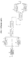
- a voice signal transmission system which encodes a voice parameter using the latter method is described below with reference to Fig. 1.
- input voice has two different frequency characteristics and a quantization circuit is designed for each of the characteristics respectively.
- the two frequency characteristics of input voice are frequency characteristic (hereinafter referred to as FLAT characteristic) in which the voice band is limited to a normal voice band and another frequency characteristic (hereinafter referred to as IRS characteristic) is emphasized in the high frequency region.
- FLAT characteristic frequency characteristic
- IRS characteristic another frequency characteristic
- Spectrum parameter extraction circuit 32 calculates a parameter representative of a spectrum envelope of input voice inputted through input terminal 31 for a frame after every fixed interval of time, and outputs the parameter as an input vector to first quantization circuit 33 and second quantization circuit 34.
- a known parameter called line spectrum pair LSP
- a method of analyzing a line spectrum pair is disclosed in Furui, "Digital voice Processing", the Publishing Society of Tokai University.
- First quantization circuit 33 is designed for the FLAT characteristic while second quantization circuit 34 is designed for the IRS characteristic.
- First quantization circuit 33 quantizes the input vector using the vector quantization described above and outputs the quantization vector to discrimination circuit 35. Further, first quantization circuit 33 outputs a code corresponding to the quantization vector to discrimination circuit 35.
- second quantization circuit 34 quantizes the input vector using the vector quantization described above and outputs the quantization vector to discrimination circuit 35. Further, second quantization circuit 34 outputs a code corresponding to the quantization vector to discrimination circuit 35.
- Discrimination circuit 35 discriminates characteristic of an input vector, either the FLAT characteristic or the IRS characteristic, based on the quantization vectors of first quantization circuit 33, second quantization circuit 34 and the input vector. Then, discrimination circuit 35 outputs a code of the input voice corresponding to the frequency characteristic and discrimination information representative of a result of the discrimination through transmission circuit 36.
- reception circuit 37 receives the code and the discrimination information transmitted thereto from transmission circuit 36 and is selectively connected to first dequantization circuit 38 or second dequantization circuit 39 in response to the discrimination information so that the selectively connected dequantization circuit may perform dequantization of the code to produce a dequantization vector corresponding to the code.
- the dequantization code is outputted from output terminal 40.
- EP-A-0504627 discloses a speech parameter coding method and apparatus which can quantize a spectrum parameter of a speech signal with a smaller number of bits than ever.
- a dividing section divides a predetermined order number of spectrum parameters, obtained by division of a speech signal into frames, for each order number of spectrum parameters smaller than the divisional order number.
- a vector quantizing section searches codebooks for the divided spectrum parameters for each order number and outputs a plurality of candidates of codevector in order of magnitude from the minimum one.
- An accumulated distortion calculating section calculates accumulated distortions for the entire order number for combinations of codevectors.
- a minimum judging section selectively outputs a combination of codevectors which minimizes the accumulated distortion thereby to quantize the spectrum parameter.
- Said quantizer can operate multi-stage vector quantization and divisional vector quantization combined together.
- Taniguchi et al.: " Speech Coding with Dynamic Bit Allocation" , Advances in Speech Coding, Vancouver, 1989, P. 157-166 relates to multi-mode coding having several speech coders, each of which has a different bit assignment for the excitation and spectral parameters. In each frame, these coders process the speech signal in parallel, and the coder which provides the best reproduced speech quality is selected. The further processing is performed with the selected code. This system changes the coding mode due to the change of frequency characteristics with time variation.
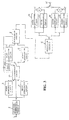
- Fig. 2 is a block diagram showing a system construction of a first embodiment of the voice signal transmission system of the present invention.
- input voice has two different frequency characteristics.
- the two frequency characteristics of the input voice are a frequency characteristic (hereinafter referred to as FLAT characteristic) in which the voice band is limited normaly and another frequency characteristic (hereinafter referred to as IRS characteristic) in which the voice is emphasized in a high frequency region.
- FLAT characteristic frequency characteristic
- IRS characteristic another frequency characteristic
- Spectrum parameter extraction circuit 2 calculates a parameter representative of a spectrum envelope of input voice inputted though input terminal 1 for a frame after every fixed number of frames, and outputs the calculated parameter as an input vector to first quantization circuit 3, second quantization circuit 4 and discrimination circuit 5.
- a known parameter called line spectrum pair is used as the parameter representative of a spectrum envelope.
- the parameter representative of a spectrum envelope is not limited to the line spectrum pair.
- First quantization circuit 3 is designed for the FLAT characteristic described above. First quantization circuit 3 quantizes the input vector from spectrum parameter extraction circuit 2 and outputs a quantization vector obtained as a result of the vector quantization to discrimination circuit 5. Further, first quantization circuit 3 outputs a code corresponding to the quantization vector to discrimination circuit 5.
- Second quantization circuit 4 is designed for the IRS characteristic described above. Second quantization circuit 4 quantizes the input vector from spectrum parameter extraction circuit 2 and outputs the quantization vector obtained as a result of the vector quantization to discrimination circuit 5. Further, second quantization circuit 4 outputs a code corresponding to the quantization vector to discrimination circuit 5.
- Discrimination circuit 5 discriminates to which frequency characteristic of the FLAT characteristic or the IRS characteristic an input voice belongs, based on the quantization vector of first quantization circuit 3, the quantization vector of second quantization circuit 4 and the input vector. Then, discrimination circuit 5 subtracts the quantization vector of the discriminated characteristic from the input vector to calculate an error vector.
- discrimination circuit 5 outputs the thus calculated error vector to third quantization circuit 6 and outputs the code corresponding to the quantization vector which was based on the calculation of the error vector and discrimination information representative of the discrimination result to transmission circuit 8.
- discrimination circuit 5 outputs the calculated error vector to fourth quantization circuit 7 and outputs the code corresponding to the quantization vector which was based on the calculation of the error vector and discrimination information representative of the discrimination result to transmission circuit 8.
- Third quantization circuit 6 is designed for the FLAT characteristic so that it may quantize the error vector of first quantization circuit 3. Third quantization circuit 6 quantizes the inputted error vector based on the discrimination result outputted from discrimination circuit 5, and outputs a code corresponding to the quantized error vector to transmission circuit 8.
- Fourth quantization circuit 7 is designed for the IRS characteristic in order to quantize the error vector of second quantization circuit 4. Fourth quantization circuit 7 quantizes the inputted error vector based on the discrimination result outputted from discrimination circuit 5 and outputs a code corresponding to the quantized error vector to transmission circuit 8.
- Transmission circuit 8 transmits the code and the discrimination information representative of the discrimination result inputted from discrimination circuit 5 as well as a code obtained from third quantization circuit 6 or fourth quantization circuit 7 to a decoding apparatus.
- Reception circuit 9 in the decoding apparatus receives the code and the discrimination information transmitted from transmission circuit 8.
- reception circuit 9 outputs the received code to first dequantization circuit 10 and third dequantization circuit 11.
- reception circuit 9 outputs the received code to second dequantization circuit 12 and fourth dequantization circuit 13.
- First dequantization circuit 10 performs dequantization corresponding to the quantization of first quantization circuit 3, and third dequantization circuit 11 performs dequantization corresponding to the quantization of third quantization circuit 6. Meanwhile, second dequantization circuit 12 performs dequantization corresponding to the quantization of second quantization circuit 4, and fourth dequantization circuit 13 performs dequantization corresponding to the quantization of fourth quantization circuit 7.
- First addition circuit 14 adds the quantization vector from first dequantization circuit 10 and the quantization vector from third dequantization circuit 11 and outputs a result of the addition to output terminal 16.
- Second addition circuit 15 adds the quantization vector from second dequantization circuit 12 and the quantization vector from fourth dequantization circuit 13 and outputs a result of the addition to output terminal 16.
- the second embodiment of the present invention is described below with reference to Fig. 3.
- the frequency characteristic of input voice does not vary with unit of frame for which processing is performed, but relies upon the entire input voice to the audio parameter encoding apparatus. Therefore, when the discrimination circuit discriminates to which one of either the FLAT characteristic or the IRS characteristic an inputted voice belongs, the deterioration of the performance of the voice parameter encoder caused by an error in discrimination can be further reduced by discriminating the present frames on the basis of weighting the results of their past discrimination respectively.
- operation of discrimination circuit 5 using a result or results of discrimination in the past is described herein after. Operations of the other components are the same as those of the first embodiment shown in Fig. 2.
- Discrimination circuit 25 discriminates to which one of either the FLAT characteristic or the IRS characteristic an inputted voice belongs, based on a result or results of past discrimination obtained from delay circuit 25a, a quantization vector of first quantization circuit 3, another quantization vector of second quantization circuit 4 and an input vector. Then, discrimination circuit 25 subtracts the quantization vector of the discriminated characteristic from the input vector to obtain an error vector and outputs the error vector to third quantization circuit 6 or fourth quantization circuit 7 in response to the result of discrimination. Further, discrimination circuit 25 outputs a corresponding code and discrimination information representative of the result of discrimination to transmission circuit 8.
- the following method may be used.
- For the evaluated value a square of distance between the quantization vectors obtained from the first and second quantization circuits and the input vector is used.
Description
- This invention relates to a voice signal transmission system which encodes a voice signal using a vector quantization circuit to transmit the coded audio signal and decodes the coded voice signal effectively at the receiver side.
- Vector quantization is known as an effective method of transmitting and storing voice, vector quantization is a method for selecting the code vector whose distance from an input vector is the shortest from a code book having a plurality of code vectors designed in advance. By transmitting and storing the selected code (number) representative of the code vector, a voice input signal can be transmitted and stored effectively. Details of the vector quantization and multistage vector quantization are disclosed, in A. Gersho et al., "Vector Quantization and Signal Compression", Kluwer Academic Publishers.
- When a voice parameter encoding apparatus is realized using the vector quantization described above, if input voice having a plurality of frequency characteristics is treated by the same encoding apparatus, the distribution of a voice parameter which represents an envelope of a voice spectrum will expand, resulting in deterioration of the performance of the voice parameter encoding apparatus. As a countermeasure against the deterioration of the performance, a method wherein the number of quantization bits of an audio parameter which represents an envelope of a voice spectrum is increased and another method wherein a quantization circuit is prepared for each frequency characteristic to detect an available optimum quantization value are adaptable.
- Operation of a voice signal transmission system which encodes a voice parameter using the latter method is described below with reference to Fig. 1. For simplified description, it is assumed that input voice has two different frequency characteristics and a quantization circuit is designed for each of the characteristics respectively. Here, it is assumed that the two frequency characteristics of input voice are frequency characteristic (hereinafter referred to as FLAT characteristic) in which the voice band is limited to a normal voice band and another frequency characteristic (hereinafter referred to as IRS characteristic) is emphasized in the high frequency region.
- Spectrum
parameter extraction circuit 32 calculates a parameter representative of a spectrum envelope of input voice inputted throughinput terminal 31 for a frame after every fixed interval of time, and outputs the parameter as an input vector tofirst quantization circuit 33 andsecond quantization circuit 34. As the parameter representative of a spectrum envelope, a known parameter called line spectrum pair (LSP) is available. A method of analyzing a line spectrum pair is disclosed in Furui, "Digital voice Processing", the Publishing Society of Tokai University. -
First quantization circuit 33 is designed for the FLAT characteristic whilesecond quantization circuit 34 is designed for the IRS characteristic.First quantization circuit 33 quantizes the input vector using the vector quantization described above and outputs the quantization vector todiscrimination circuit 35. Further,first quantization circuit 33 outputs a code corresponding to the quantization vector todiscrimination circuit 35. - Similarly,
second quantization circuit 34 quantizes the input vector using the vector quantization described above and outputs the quantization vector todiscrimination circuit 35. Further,second quantization circuit 34 outputs a code corresponding to the quantization vector todiscrimination circuit 35. -
Discrimination circuit 35 discriminates characteristic of an input vector, either the FLAT characteristic or the IRS characteristic, based on the quantization vectors offirst quantization circuit 33,second quantization circuit 34 and the input vector. Then,discrimination circuit 35 outputs a code of the input voice corresponding to the frequency characteristic and discrimination information representative of a result of the discrimination throughtransmission circuit 36. - In the decoding apparatus,
reception circuit 37 receives the code and the discrimination information transmitted thereto fromtransmission circuit 36 and is selectively connected tofirst dequantization circuit 38 orsecond dequantization circuit 39 in response to the discrimination information so that the selectively connected dequantization circuit may perform dequantization of the code to produce a dequantization vector corresponding to the code. The dequantization code is outputted fromoutput terminal 40. - However, since all of the prior art apparatus described above require comparison processing with a large number of code vectors, the amount of required calculation is very great. Further, even if multistage vector quantization which involves a reduced amount of calculation is used, real time processing is still difficult.
- EP-A-0504627 discloses a speech parameter coding method and apparatus which can quantize a spectrum parameter of a speech signal with a smaller number of bits than ever. A dividing section divides a predetermined order number of spectrum parameters, obtained by division of a speech signal into frames, for each order number of spectrum parameters smaller than the divisional order number. A vector quantizing section searches codebooks for the divided spectrum parameters for each order number and outputs a plurality of candidates of codevector in order of magnitude from the minimum one. An accumulated distortion calculating section calculates accumulated distortions for the entire order number for combinations of codevectors. A minimum judging section selectively outputs a combination of codevectors which minimizes the accumulated distortion thereby to quantize the spectrum parameter. Said quantizer can operate multi-stage vector quantization and divisional vector quantization combined together.
- Taniguchi et al.: " Speech Coding with Dynamic Bit Allocation" , Advances in Speech Coding, Vancouver, 1989, P. 157-166 relates to multi-mode coding having several speech coders, each of which has a different bit assignment for the excitation and spectral parameters. In each frame, these coders process the speech signal in parallel, and the coder which provides the best reproduced speech quality is selected. The further processing is performed with the selected code. This system changes the coding mode due to the change of frequency characteristics with time variation.
- It is an object of the present invention to provide a voice signal transmission system which reduces the quantity of calculation by suppressing possible deterioration of performance due to expansion in the distribution of a voice parameter representative of an envelope of a voice spectrum when input voice having a plurality of frequency characteristics is treated simultaneously and a voice parameter encoding apparatus and decoding apparatus for use with the voice signal transmission system. This object is achieved with the features of the claims.
- Fig. 1 is a block diagram showing a system construction of an example of a conventional audio signal transmission system;
- Fig. 2 is a block diagram showing a system construction of a first embodiment of the voice signal transmission system of the present invention; and
- Fig. 3 is a block diagram showing a system construction of a second embodiment of the voice signal transmission system of the present invention.
-
- Embodiments of the present invention are described below with reference to the drawings. Fig. 2 is a block diagram showing a system construction of a first embodiment of the voice signal transmission system of the present invention. In the present embodiment, for practical and simplified description, it is assumed that input voice has two different frequency characteristics. Here, it is assumed that the two frequency characteristics of the input voice are a frequency characteristic (hereinafter referred to as FLAT characteristic) in which the voice band is limited normaly and another frequency characteristic (hereinafter referred to as IRS characteristic) in which the voice is emphasized in a high frequency region.
- Spectrum
parameter extraction circuit 2 calculates a parameter representative of a spectrum envelope of input voice inputted though input terminal 1 for a frame after every fixed number of frames, and outputs the calculated parameter as an input vector tofirst quantization circuit 3, second quantization circuit 4 anddiscrimination circuit 5. As the parameter representative of a spectrum envelope, a known parameter called line spectrum pair is used. Naturally, the parameter representative of a spectrum envelope is not limited to the line spectrum pair. -
First quantization circuit 3 is designed for the FLAT characteristic described above.First quantization circuit 3 quantizes the input vector from spectrumparameter extraction circuit 2 and outputs a quantization vector obtained as a result of the vector quantization todiscrimination circuit 5. Further,first quantization circuit 3 outputs a code corresponding to the quantization vector todiscrimination circuit 5. - Second quantization circuit 4 is designed for the IRS characteristic described above. Second quantization circuit 4 quantizes the input vector from spectrum
parameter extraction circuit 2 and outputs the quantization vector obtained as a result of the vector quantization todiscrimination circuit 5. Further, second quantization circuit 4 outputs a code corresponding to the quantization vector todiscrimination circuit 5. -
Discrimination circuit 5 discriminates to which frequency characteristic of the FLAT characteristic or the IRS characteristic an input voice belongs, based on the quantization vector offirst quantization circuit 3, the quantization vector of second quantization circuit 4 and the input vector. Then,discrimination circuit 5 subtracts the quantization vector of the discriminated characteristic from the input vector to calculate an error vector. When the discrimination result is the FLAT characteristic,discrimination circuit 5 outputs the thus calculated error vector to third quantization circuit 6 and outputs the code corresponding to the quantization vector which was based on the calculation of the error vector and discrimination information representative of the discrimination result totransmission circuit 8. When the discrimination result is the IRS characteristic,discrimination circuit 5 outputs the calculated error vector tofourth quantization circuit 7 and outputs the code corresponding to the quantization vector which was based on the calculation of the error vector and discrimination information representative of the discrimination result totransmission circuit 8. - Third quantization circuit 6 is designed for the FLAT characteristic so that it may quantize the error vector of
first quantization circuit 3. Third quantization circuit 6 quantizes the inputted error vector based on the discrimination result outputted fromdiscrimination circuit 5, and outputs a code corresponding to the quantized error vector totransmission circuit 8. -
Fourth quantization circuit 7 is designed for the IRS characteristic in order to quantize the error vector of second quantization circuit 4.Fourth quantization circuit 7 quantizes the inputted error vector based on the discrimination result outputted fromdiscrimination circuit 5 and outputs a code corresponding to the quantized error vector totransmission circuit 8. -
Transmission circuit 8 transmits the code and the discrimination information representative of the discrimination result inputted fromdiscrimination circuit 5 as well as a code obtained from third quantization circuit 6 orfourth quantization circuit 7 to a decoding apparatus. - Reception circuit 9 in the decoding apparatus receives the code and the discrimination information transmitted from
transmission circuit 8. When the received discrimination information represents the FLAT characteristic, reception circuit 9 outputs the received code tofirst dequantization circuit 10 and third dequantization circuit 11. When the received discrimination information represents the IRS characteristic, reception circuit 9 outputs the received code tosecond dequantization circuit 12 andfourth dequantization circuit 13. -
First dequantization circuit 10 performs dequantization corresponding to the quantization offirst quantization circuit 3, and third dequantization circuit 11 performs dequantization corresponding to the quantization of third quantization circuit 6. Meanwhile,second dequantization circuit 12 performs dequantization corresponding to the quantization of second quantization circuit 4, andfourth dequantization circuit 13 performs dequantization corresponding to the quantization offourth quantization circuit 7. -
First addition circuit 14 adds the quantization vector fromfirst dequantization circuit 10 and the quantization vector from third dequantization circuit 11 and outputs a result of the addition tooutput terminal 16.Second addition circuit 15 adds the quantization vector fromsecond dequantization circuit 12 and the quantization vector fromfourth dequantization circuit 13 and outputs a result of the addition tooutput terminal 16. - While the embodiment described above is applied to the case wherein input voice has two different frequency characteristics, a method of increasing number P, the number of frequency characteristics can be analogized readily. Further, when number P, the number of frequency characteristics, is increased, number K (K < P), the number of potential frequency characteristics, shall be quantized by
discrimination circuit 5 to determine a corresponding frequency characteristic and a corresponding code based on a final result of the quantization. - The second embodiment of the present invention is described below with reference to Fig. 3. The frequency characteristic of input voice does not vary with unit of frame for which processing is performed, but relies upon the entire input voice to the audio parameter encoding apparatus. Therefore, when the discrimination circuit discriminates to which one of either the FLAT characteristic or the IRS characteristic an inputted voice belongs, the deterioration of the performance of the voice parameter encoder caused by an error in discrimination can be further reduced by discriminating the present frames on the basis of weighting the results of their past discrimination respectively. For simplified description of the second embodiment, operation of
discrimination circuit 5 using a result or results of discrimination in the past is described herein after. Operations of the other components are the same as those of the first embodiment shown in Fig. 2. -
Discrimination circuit 25 discriminates to which one of either the FLAT characteristic or the IRS characteristic an inputted voice belongs, based on a result or results of past discrimination obtained from delay circuit 25a, a quantization vector offirst quantization circuit 3, another quantization vector of second quantization circuit 4 and an input vector. Then,discrimination circuit 25 subtracts the quantization vector of the discriminated characteristic from the input vector to obtain an error vector and outputs the error vector to third quantization circuit 6 orfourth quantization circuit 7 in response to the result of discrimination. Further,discrimination circuit 25 outputs a corresponding code and discrimination information representative of the result of discrimination totransmission circuit 8. - As a method for weighting an evaluated value at present with a result or results of past discrimination, for example, the following method may be used. For the evaluated value, a square of distance between the quantization vectors obtained from the first and second quantization circuits and the input vector is used.
- (1) The weighting coefficient to a quantization vector for the frequency characteristic which has the same result of past discrimination is set as predetermined value W (W < 1, for example, 0.8), and the weighting coefficient to a quantization vector for the other frequency characteristic having no discrimination result is set as 1.0.
- (2) When the same result of discrimination successively occurs, weighting coefficient W(x) is varied with number (x) of the successive frames. For example, weighting coefficients W(x) is set to W(0) = 1.0, W(1) = 0.9, W(2) = 0.8, ..., and W(5) = 0.5. In the present example, when repetition number x of the same discrimination result is greater than 5, x is set to x = 5. By discriminating the frequency characteristic of the input voice using a result of past discrimination in accordance with the method described above, the discrimination value can be stabilized in successive frames.
-
- As described above, according to the present invention as defined in the appended claims, since it is discriminated to which frequency characteristics an input vector belongs and limits the operation of quantization circuit only for the quantization circuits which are provided for the discriminated frequency characteristic, the amount of calculation can be reduced, and deterioration in performance can be prevented.
Claims (4)
- A voice parameter encoding apparatus, comprising:a spectral parameter extraction circuit (2) for calculating a voice parameter representative of a spectrum envelope of a voice input signal (1) for each frame of every predetermined fixed interval of time;a first quantization circuit (3) for quantizing the voice parameter outputted from said spectrum parameter extraction circuit (2) assuming that the input signal has a first frequency characteristic, for outputting a first quantization vector and for outputting a first code representative of the first quantization vector;a second quantization circuit (4) for quantizing the voice parameter outputted from said spectrum parameter extraction circuit (2) assuming that the input signal has a second frequency characteristic, for outputting a second quantization vector and for outputting a second code representative of the second quantization vector;a discrimination circuit (5; 25) for receiving the first and second quantization vectors and the voice parameter outputted from said spectrum parameter extraction circuit (2), discriminating and selecting either one of the first or second quantization vectors which is nearer to the voice parameter outputted from said spectrum parameter extraction circuit (2), calculating a difference between the selected first or second quantization vector and the voice parameter outputted from said spectrum parameter extraction circuit (2) as an error vector, outputting a first code or a second code representative of the selected first or second quantization vector together with discrimination information, and outputting, when the first quantization vector is selected, the calculated error vector to a first route, but outputting, when the second quantization vector is selected, the calculated error vector to a second route;a third quantization circuit (6) for quantizing, when the error vector is outputted from said discrimination circuit to said first route, the outputted error vector and outputting a third code corresponding to the quantization vector obtained by the quantization;a fourth quantization circuit (7) for quantizing the outputted error vector when the error vector is outputted from said discrimination circuit to said second route, and outputting a fourth code corresponding to the quantization vector obtained by the quantization; anda transmission circuit (8) for receiving the first or second code outputted from said discrimination circuit (5; 25), the discrimination information, and the third or fourth code outputted from said third (6) or fourth (7) quantization circuit as inputs thereto and outputting the inputs to a transmission line.
- An apparatus as claimed in claim 1, wherein said discrimination circuit (5; 25) refers to, upon selection of either one of the first or second quantization vectors which is nearer to the voice parameter outputted from said spectrum parameter extraction circuit, results of discrimination performed in the past as a factor for weight.
- A voice parameter decoding apparatus for decoding a transmission signal from a voice parameter encoding apparatus, said voice parameter encoding apparatus comprising:a spectral parameter extraction circuit (2) for calculating a voice parameter representative of a spectrum envelope of a voice input signal (1) for each frame of every predetermined fixed interval of time;a first quantization circuit (3) for quantizing the voice parameter outputted from said spectrum parameter extraction circuit (2) assuming that the input signal has a first frequency characteristic, for outputting a first quantization vector and for outputting a first code representative of the first quantization vector;a second quantization circuit (4) for quantizing the voice parameter outputted from said spectrum parameter extraction circuit (2) assuming that the input signal has a second frequency characteristic, for outputting a second quantization vector and for outputting a second code representative of the second quantization vector;a discrimination circuit (5; 25) for receiving the first and second quantization vectors and the voice parameter outputted from said spectrum parameter extraction circuit (2), discriminating and selecting either one of the first or second quantization vectors which is nearer to the voice parameter outputted from said spectrum parameter extraction circuit (2), calculating a difference between the selected first or second quantization vector and the voice parameter outputted from said spectrum parameter extraction circuit (2) as an error vector, outputting a first code or a second code representative of the selected first or second quantization vector together with discrimination information, and outputting, when the first quantization vector is selected, the calculated error vector to a first route, but outputting, when the second quantization vector is selected, the calculated error vector to a second route;a third quantization circuit (6) for quantizing, when the error vector is outputted from said discrimination circuit (5; 25) to said first route, the outputted error vector and outputting a third code corresponding to the quantization vector obtained by the quantization;a fourth quantization circuit (7) for quantizing the outputted error vector when the error vector is outputted from said discrimination circuit (5; 25) to said second route, and outputting a fourth code corresponding to the quantization vector obtained by the quantization, anda transmission circuit (8) for receiving the first or second code outputted from said discrimination circuit (5; 25), the discrimination information, and the third or fourth code outputted from said third (6) or fourth (7) quantization circuit as inputs thereto and outputting the inputs to a transmission line, said voice parameter decoding apparatus further comprising:a reception circuit (9) for receiving the transmission signal, discriminating from the discrimination information of the transmission signal whether the transmission signal is originated from either one of said first (3) or third (6) quantization circuit or from either one of said second (4) or fourth (7) quantization circuit and outputting, when a result of the discrimination shows that the transmission signal was originated from said first (3) or third (6) quantization circuit, the transmission signal to a third route, but outputting, when the result of the discrimination shows that the transmission signal was originated from the second (4) or fourth (7) quantization circuit, the transmission signal to a fourth route;a first dequantization circuit (10) for dequantizing the first code;a third dequantization circuit (11) for dequantizing the third code;a first adder circuit (14) for adding outputs of said first (10) and third (11) dequantization circuits and outputting a result of the addition to an output terminal (16) when the transmission signal is outputted to said third route; anda second dequantization circuit (12) for dequantizing the second code;a fourth dequantization circuit (13) for dequantizing the fourth code;a second adder circuit (15) for adding outputs of said second (12) and fourth (13) dequantization circuits and outputting a result of the addition to said output terminal (16) when the transmission signal is outputted to said fourth route.
- A voice signal transmission system, comprising a voice parameter encoding apparatus as claimed in claim 1 or 2, a voice parameter decoding apparatus as claimed in claim 3, and a transmission line for interconnecting between said transmission circuit of said voice parameter encoding apparatus and said reception circuit (9) of said voice parameter decoding apparatus.
Applications Claiming Priority (3)
| Application Number | Priority Date | Filing Date | Title |
|---|---|---|---|
| JP7005090A JP2982637B2 (en) | 1995-01-17 | 1995-01-17 | Speech signal transmission system using spectrum parameters, and speech parameter encoding device and decoding device used therefor |
| JP5090/95 | 1995-01-17 | ||
| JP509095 | 1995-01-17 |
Publications (3)
| Publication Number | Publication Date |
|---|---|
| EP0723257A2 EP0723257A2 (en) | 1996-07-24 |
| EP0723257A3 EP0723257A3 (en) | 1998-01-07 |
| EP0723257B1 true EP0723257B1 (en) | 2002-04-24 |
Family
ID=11601703
Family Applications (1)
| Application Number | Title | Priority Date | Filing Date |
|---|---|---|---|
| EP96100660A Expired - Lifetime EP0723257B1 (en) | 1995-01-17 | 1996-01-17 | Voice signal transmission system using spectral parameter and voice parameter encoding apparatus and decoding apparatus used for the voice signal transmission system |
Country Status (5)
| Country | Link |
|---|---|
| US (1) | US5734679A (en) |
| EP (1) | EP0723257B1 (en) |
| JP (1) | JP2982637B2 (en) |
| CA (1) | CA2167327C (en) |
| DE (1) | DE69620808T2 (en) |
Families Citing this family (4)
| Publication number | Priority date | Publication date | Assignee | Title |
|---|---|---|---|---|
| US5924064A (en) * | 1996-10-07 | 1999-07-13 | Picturetel Corporation | Variable length coding using a plurality of region bit allocation patterns |
| US6178405B1 (en) | 1996-11-18 | 2001-01-23 | Innomedia Pte Ltd. | Concatenation compression method |
| US6947886B2 (en) * | 2002-02-21 | 2005-09-20 | The Regents Of The University Of California | Scalable compression of audio and other signals |
| AU2003274520A1 (en) * | 2002-11-28 | 2004-06-18 | Koninklijke Philips Electronics N.V. | Coding an audio signal |
Family Cites Families (7)
| Publication number | Priority date | Publication date | Assignee | Title |
|---|---|---|---|---|
| JPS6032100A (en) * | 1983-08-03 | 1985-02-19 | 日本電気株式会社 | Lsp type pattern matching vocoder |
| JP2605256B2 (en) * | 1985-03-20 | 1997-04-30 | 日本電気株式会社 | LSP pattern matching vocoder |
| JP3114197B2 (en) * | 1990-11-02 | 2000-12-04 | 日本電気株式会社 | Voice parameter coding method |
| US5271089A (en) * | 1990-11-02 | 1993-12-14 | Nec Corporation | Speech parameter encoding method capable of transmitting a spectrum parameter at a reduced number of bits |
| JP3151874B2 (en) * | 1991-02-26 | 2001-04-03 | 日本電気株式会社 | Voice parameter coding method and apparatus |
| JP2936757B2 (en) * | 1991-03-08 | 1999-08-23 | 三菱電機株式会社 | Quantizer |
| JP3088163B2 (en) * | 1991-12-18 | 2000-09-18 | 沖電気工業株式会社 | LSP coefficient quantization method |
-
1995
- 1995-01-17 JP JP7005090A patent/JP2982637B2/en not_active Expired - Fee Related
-
1996
- 1996-01-16 CA CA002167327A patent/CA2167327C/en not_active Expired - Fee Related
- 1996-01-16 US US08/584,950 patent/US5734679A/en not_active Expired - Lifetime
- 1996-01-17 EP EP96100660A patent/EP0723257B1/en not_active Expired - Lifetime
- 1996-01-17 DE DE69620808T patent/DE69620808T2/en not_active Expired - Fee Related
Also Published As
| Publication number | Publication date |
|---|---|
| DE69620808D1 (en) | 2002-05-29 |
| JPH08195722A (en) | 1996-07-30 |
| CA2167327A1 (en) | 1996-07-18 |
| CA2167327C (en) | 1999-10-12 |
| EP0723257A2 (en) | 1996-07-24 |
| EP0723257A3 (en) | 1998-01-07 |
| JP2982637B2 (en) | 1999-11-29 |
| US5734679A (en) | 1998-03-31 |
| DE69620808T2 (en) | 2002-09-26 |
Similar Documents
| Publication | Publication Date | Title |
|---|---|---|
| US5125030A (en) | Speech signal coding/decoding system based on the type of speech signal | |
| US5729655A (en) | Method and apparatus for speech compression using multi-mode code excited linear predictive coding | |
| US6023672A (en) | Speech coder | |
| EP0696026B1 (en) | Speech coding device | |
| AU703046B2 (en) | Speech encoding method | |
| US5140638A (en) | Speech coding system and a method of encoding speech | |
| US20110270608A1 (en) | Method and apparatus for receiving an encoded speech signal | |
| US5426718A (en) | Speech signal coding using correlation valves between subframes | |
| US5682407A (en) | Voice coder for coding voice signal with code-excited linear prediction coding | |
| US5113448A (en) | Speech coding/decoding system with reduced quantization noise | |
| EP1162604B1 (en) | High quality speech coder at low bit rates | |
| US5526464A (en) | Reducing search complexity for code-excited linear prediction (CELP) coding | |
| US6484139B2 (en) | Voice frequency-band encoder having separate quantizing units for voice and non-voice encoding | |
| CA2090205C (en) | Speech coding system | |
| EP0723257B1 (en) | Voice signal transmission system using spectral parameter and voice parameter encoding apparatus and decoding apparatus used for the voice signal transmission system | |
| US7076424B2 (en) | Speech coder/decoder | |
| EP0855699A2 (en) | Multipulse-excited speech coder/decoder | |
| EP0483882B1 (en) | Speech parameter encoding method capable of transmitting a spectrum parameter with a reduced number of bits | |
| EP1334485B1 (en) | Speech codec and method for generating a vector codebook and encoding/decoding speech signals | |
| EP0662682A2 (en) | Speech signal coding | |
| JP3350340B2 (en) | Voice coding method and voice decoding method | |
| JPH0749700A (en) | Celp type voice decoder | |
| JPH05341800A (en) | Voice coding device | |
| JPH08254999A (en) | Gain quantizing device and voice encoding/decoding device | |
| JPH04114516A (en) | Sound encoding device |
Legal Events
| Date | Code | Title | Description |
|---|---|---|---|
| PUAI | Public reference made under article 153(3) epc to a published international application that has entered the european phase |
Free format text: ORIGINAL CODE: 0009012 |
|
| AK | Designated contracting states |
Kind code of ref document: A2 Designated state(s): DE FR GB IT SE |
|
| PUAL | Search report despatched |
Free format text: ORIGINAL CODE: 0009013 |
|
| AK | Designated contracting states |
Kind code of ref document: A3 Designated state(s): DE FR GB IT SE |
|
| 17P | Request for examination filed |
Effective date: 19971202 |
|
| 17Q | First examination report despatched |
Effective date: 20000315 |
|
| GRAG | Despatch of communication of intention to grant |
Free format text: ORIGINAL CODE: EPIDOS AGRA |
|
| RIC1 | Information provided on ipc code assigned before grant |
Free format text: 7G 10L 19/02 A |
|
| GRAG | Despatch of communication of intention to grant |
Free format text: ORIGINAL CODE: EPIDOS AGRA |
|
| GRAG | Despatch of communication of intention to grant |
Free format text: ORIGINAL CODE: EPIDOS AGRA |
|
| GRAH | Despatch of communication of intention to grant a patent |
Free format text: ORIGINAL CODE: EPIDOS IGRA |
|
| REG | Reference to a national code |
Ref country code: GB Ref legal event code: IF02 |
|
| GRAH | Despatch of communication of intention to grant a patent |
Free format text: ORIGINAL CODE: EPIDOS IGRA |
|
| GRAA | (expected) grant |
Free format text: ORIGINAL CODE: 0009210 |
|
| AK | Designated contracting states |
Kind code of ref document: B1 Designated state(s): DE FR GB IT SE |
|
| REG | Reference to a national code |
Ref country code: GB Ref legal event code: FG4D |
|
| REF | Corresponds to: |
Ref document number: 69620808 Country of ref document: DE Date of ref document: 20020529 |
|
| ET | Fr: translation filed | ||
| PLBE | No opposition filed within time limit |
Free format text: ORIGINAL CODE: 0009261 |
|
| STAA | Information on the status of an ep patent application or granted ep patent |
Free format text: STATUS: NO OPPOSITION FILED WITHIN TIME LIMIT |
|
| 26N | No opposition filed |
Effective date: 20030127 |
|
| PGFP | Annual fee paid to national office [announced via postgrant information from national office to epo] |
Ref country code: DE Payment date: 20090115 Year of fee payment: 14 |
|
| PGFP | Annual fee paid to national office [announced via postgrant information from national office to epo] |
Ref country code: GB Payment date: 20090114 Year of fee payment: 14 |
|
| PGFP | Annual fee paid to national office [announced via postgrant information from national office to epo] |
Ref country code: IT Payment date: 20090127 Year of fee payment: 14 |
|
| PGFP | Annual fee paid to national office [announced via postgrant information from national office to epo] |
Ref country code: FR Payment date: 20090113 Year of fee payment: 14 |
|
| PGFP | Annual fee paid to national office [announced via postgrant information from national office to epo] |
Ref country code: SE Payment date: 20091218 Year of fee payment: 15 |
|
| GBPC | Gb: european patent ceased through non-payment of renewal fee |
Effective date: 20100117 |
|
| REG | Reference to a national code |
Ref country code: FR Ref legal event code: ST Effective date: 20100930 |
|
| PG25 | Lapsed in a contracting state [announced via postgrant information from national office to epo] |
Ref country code: FR Free format text: LAPSE BECAUSE OF NON-PAYMENT OF DUE FEES Effective date: 20100201 |
|
| PG25 | Lapsed in a contracting state [announced via postgrant information from national office to epo] |
Ref country code: DE Free format text: LAPSE BECAUSE OF NON-PAYMENT OF DUE FEES Effective date: 20100803 |
|
| PG25 | Lapsed in a contracting state [announced via postgrant information from national office to epo] |
Ref country code: GB Free format text: LAPSE BECAUSE OF NON-PAYMENT OF DUE FEES Effective date: 20100117 |
|
| PG25 | Lapsed in a contracting state [announced via postgrant information from national office to epo] |
Ref country code: IT Free format text: LAPSE BECAUSE OF NON-PAYMENT OF DUE FEES Effective date: 20100117 |
|
| REG | Reference to a national code |
Ref country code: SE Ref legal event code: EUG |
|
| PG25 | Lapsed in a contracting state [announced via postgrant information from national office to epo] |
Ref country code: SE Free format text: LAPSE BECAUSE OF NON-PAYMENT OF DUE FEES Effective date: 20110118 |