EP1091403A2 - Heat sink - Google Patents
Heat sink Download PDFInfo
- Publication number
- EP1091403A2 EP1091403A2 EP00121512A EP00121512A EP1091403A2 EP 1091403 A2 EP1091403 A2 EP 1091403A2 EP 00121512 A EP00121512 A EP 00121512A EP 00121512 A EP00121512 A EP 00121512A EP 1091403 A2 EP1091403 A2 EP 1091403A2
- Authority
- EP
- European Patent Office
- Prior art keywords
- heat sink
- fin
- outer end
- circular
- fins
- Prior art date
- Legal status (The legal status is an assumption and is not a legal conclusion. Google has not performed a legal analysis and makes no representation as to the accuracy of the status listed.)
- Granted
Links
Images


Classifications
-
- H—ELECTRICITY
- H10—SEMICONDUCTOR DEVICES; ELECTRIC SOLID-STATE DEVICES NOT OTHERWISE PROVIDED FOR
- H10W—GENERIC PACKAGES, INTERCONNECTIONS, CONNECTORS OR OTHER CONSTRUCTIONAL DETAILS OF DEVICES COVERED BY CLASS H10
- H10W40/00—Arrangements for thermal protection or thermal control
- H10W40/10—Arrangements for heating
-
- H—ELECTRICITY
- H10—SEMICONDUCTOR DEVICES; ELECTRIC SOLID-STATE DEVICES NOT OTHERWISE PROVIDED FOR
- H10W—GENERIC PACKAGES, INTERCONNECTIONS, CONNECTORS OR OTHER CONSTRUCTIONAL DETAILS OF DEVICES COVERED BY CLASS H10
- H10W40/00—Arrangements for thermal protection or thermal control
- H10W40/20—Arrangements for cooling
- H10W40/22—Arrangements for cooling characterised by their shape, e.g. having conical or cylindrical projections
- H10W40/226—Arrangements for cooling characterised by their shape, e.g. having conical or cylindrical projections characterised by projecting parts, e.g. fins to increase surface area
-
- B—PERFORMING OPERATIONS; TRANSPORTING
- B21—MECHANICAL METAL-WORKING WITHOUT ESSENTIALLY REMOVING MATERIAL; PUNCHING METAL
- B21J—FORGING; HAMMERING; PRESSING METAL; RIVETING; FORGE FURNACES
- B21J5/00—Methods for forging, hammering, or pressing; Special equipment or accessories therefor
- B21J5/06—Methods for forging, hammering, or pressing; Special equipment or accessories therefor for performing particular operations
- B21J5/068—Shaving, skiving or scarifying for forming lifted portions, e.g. slices or barbs, on the surface of the material
-
- F—MECHANICAL ENGINEERING; LIGHTING; HEATING; WEAPONS; BLASTING
- F28—HEAT EXCHANGE IN GENERAL
- F28F—DETAILS OF HEAT-EXCHANGE AND HEAT-TRANSFER APPARATUS, OF GENERAL APPLICATION
- F28F3/00—Plate-like or laminated elements; Assemblies of plate-like or laminated elements
- F28F3/02—Elements or assemblies thereof with means for increasing heat-transfer area, e.g. with fins, with recesses, with corrugations
- F28F3/04—Elements or assemblies thereof with means for increasing heat-transfer area, e.g. with fins, with recesses, with corrugations the means being integral with the element
- F28F3/048—Elements or assemblies thereof with means for increasing heat-transfer area, e.g. with fins, with recesses, with corrugations the means being integral with the element in the form of ribs integral with the element or local variations in thickness of the element, e.g. grooves, microchannels
Definitions
- the present invention relates to heat sinks which are to be used for semiconductor devices or like heat generating articles as attached to the heat sink or to be attached to electronic devices having a heat generating article incorporated therein for dissipating the heat generated by the article.
- aluminum as used herein and in the appended claims includes pure aluminum, commercial aluminum containing traces of impurities and aluminum alloys.
- front refers to the front side of the fins.
- Heat sinks comprising at least one row of many rectangular tonguelike fins formed on one surface of a heat dissipating base plate include those already widely known wherein each of the fins is bent forward at the entire outer end portion thereof to form a curl portion so as to confine the height of the fin to a predetermined tolerance range and to prevent cutting of the hand.
- the curl portions are formed by using a cutting tool device which comprises a slider movable forward and rearward and provided at its lower end with a cutting tool having a cutting face, and a curl forming member attached to the upper end of the slider and projecting forward for guiding the outer end of the fin produced by cutting to a raised form and acting to extend upward, by coming into contact with the fin end so that the fin end portion is bent forward.
- a cutting tool device which comprises a slider movable forward and rearward and provided at its lower end with a cutting tool having a cutting face, and a curl forming member attached to the upper end of the slider and projecting forward for guiding the outer end of the fin produced by cutting to a raised form and acting to extend upward, by coming into contact with the fin end so that the fin end portion is bent forward.
- the fin produced by cutting to the raised form is rectangular, the horizontal straight outer end is brought in its entirety into striking contact with the lower surface of the curl forming member at a time. Consequently, the fin is likely to deform by buckling, while the base parts of opposite ends of the curl portion are positioned at opposite side edge corners of the fin and are therefore likely to wound the hand as by cutting. Thus, the fins still remain to be improved to ensure safety.
- An object of the present invention is to provide a heat sink having fins which are unlikely to deform by buckling when bent to form curl portions and which are also free of the likelihood of injuring the hand as by cutting.
- the present invention provides a heat sink comprising at least one row of many tonguelike fins formed on one surface of a heat dissipating base plate, each of the fins having a circular-arc outer end, a midportion only of the entire circular-arc outer end portion being bent forward into a curl portion, the end portion having opposite side parts other than the midportion and remaining unbent as arcuate portions.
- the curl portion can be formed without causing deformation of the fin due to backling and obviates the likelihood of cutting the hand to ensure safety.
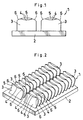
- FIGS. 1 and 2 show a heat sink 1 of the present invention, which comprises two rows of many tonguelike fins 3 formed on one surface of a heat dissipating base plate 2.
- Each of the fins 3 has a circular-arc outer end 4, and the midportion only of the entire circular-arc outer end portion is bent forward into a curl portion 5.
- the end portion has opposite side parts other than the midportion and remaining unbent as arcuate portions 6.
- a heat sink blank 10 of aluminum extrudate is first formed which comprises a heat dissipating base plate forming portion 7 having two fin forming ridges 9 formed on the upper surface of the portion 7, corresponding in number to the number of rows of tonguelike fins 3 and each having an upper surface 8 of upwardly bulging circular-arc cross section as shown in FIG. 3.
- tonguelike fins 3 are formed by cutting the two fin forming ridges 9 to a raised form at a predetermined interval from one end of each ridge using a cutting tool device 15 which, as shown in FIG. 4, comprises a slider 13 slidingly movable forward and rearward and provided at its lower end with a cutting tool 12 having a cutting face 11, and a curl forming member 14 attached to the upper end of the slider 13 and projecting forward for guiding the outer end of the fin produced by cutting to the raised form and acting to extend upward, by coming into contact with the fin end so that the fin end portion is bent forward.
- the upper surface 8 of each fin forming ridge 9 has a circular-arc cross section, with the result that the outer end of the fin 3 thus produced by cutting to the raised form and acting to extend upward invariably assumes a circular-arc form.
- FIG. 5 shows a conventional heat sink 21, which comprises two rows of many rectangular tonguelike fins 23 formed on one surface of a heat dissipating base plate 22 and each bent forward at its entire outer end portion to form a curl portion 24.
- the conventional heat sink 21 is fabricated by forming a heat sink blank 28 of aluminum extrudate which comprises a heat dissipating base plate forming portion 25 having two fin forming ridges 27 formed on the upper surface of the portion 25 integrally therewith, corresponding in number to the number of rows of tonguelike fins 23 and each having an upper surface 26 in the form of a horizontal straight line in cross section as shown in FIG. 6, and cutting the fin forming ridges 27 to a raised form at a predetermined interval from one end of the ridge with use of the cutting tool device 15 to form many tonguelike fins 23.
- the horizontal straight outer end 29 is brought in its entirety into striking contact with the lower surface of the curl forming member 14 at a time as previously described. This entails the likelihood that the fin 23 will deform by buckling, while opposite ends 30 of the curl portion 24 are positioned at opposite side edge corners of the fin 23, consequently failing to ensure safety.
- the tonguelike fin 3 formed by cutting to a raised form has a circular-arc outer end, which therefore initially comes into point contact with the curl forming member 14 of the cutting tool device 15 and is then bent only at its midportion by contacting the member 14 over a gradually increasing area, whereby the curl portion 5 is formed. Consequently, no deformation occurs in the fin 3 due to buckling. Since the opposite side parts of the end portion other than the midportion remain unbent as arcuate portions 6, the base parts of opposite ends of the curl portion that would cut the hand are not positioned on the side edge lines of the fin 3.
Landscapes
- Engineering & Computer Science (AREA)
- Mechanical Engineering (AREA)
- Cooling Or The Like Of Semiconductors Or Solid State Devices (AREA)
- Bending Of Plates, Rods, And Pipes (AREA)
- Body Structure For Vehicles (AREA)
- Thermotherapy And Cooling Therapy Devices (AREA)
- Resistance Heating (AREA)
- Domestic Hot-Water Supply Systems And Details Of Heating Systems (AREA)
- Floor Finish (AREA)
Abstract
Description
Claims (2)
- A heat sink comprising at least one row of many tonguelike fins formed on one surface of a heat dissipating base plate, each of the fins having a circular-arc outer end, a midportion only of the entire circular-arc outer end portion being bent forward into a curl portion, the end portion having opposite side parts other than the midportion and remaining unbent as arcuate portions.
- A heat sink according to claim 1 which is fabricated from a blank made of an aluminum extrudate and comprising a heat dissipating base plate forming portion having at least one fin forming ridge formed on an upper surface of the base plate forming portion, corresponding in number to the number of rows of tonguelike fins and having an upper surface of upwardly bulging circular-arc cross section.
Applications Claiming Priority (2)
| Application Number | Priority Date | Filing Date | Title |
|---|---|---|---|
| JP28230799 | 1999-10-04 | ||
| JP28230799 | 1999-10-04 |
Publications (3)
| Publication Number | Publication Date |
|---|---|
| EP1091403A2 true EP1091403A2 (en) | 2001-04-11 |
| EP1091403A3 EP1091403A3 (en) | 2003-01-15 |
| EP1091403B1 EP1091403B1 (en) | 2006-03-29 |
Family
ID=17650727
Family Applications (1)
| Application Number | Title | Priority Date | Filing Date |
|---|---|---|---|
| EP00121512A Expired - Lifetime EP1091403B1 (en) | 1999-10-04 | 2000-09-29 | Heat sink |
Country Status (8)
| Country | Link |
|---|---|
| US (1) | US6349762B2 (en) |
| EP (1) | EP1091403B1 (en) |
| KR (1) | KR100719859B1 (en) |
| CN (1) | CN1189937C (en) |
| AT (1) | ATE322082T1 (en) |
| CA (1) | CA2322077A1 (en) |
| DE (1) | DE60026913T2 (en) |
| TW (1) | TW473609B (en) |
Cited By (1)
| Publication number | Priority date | Publication date | Assignee | Title |
|---|---|---|---|---|
| DE202014002060U1 (en) | 2014-03-06 | 2015-04-08 | HKR Seuffer Automotive GmbH & Co. KG | Cooling device and cooling arrangement with the cooling device |
Families Citing this family (12)
| Publication number | Priority date | Publication date | Assignee | Title |
|---|---|---|---|---|
| AU2003248539A1 (en) * | 2002-05-17 | 2003-12-02 | William M. Janvrin | Photovoltaic module with adjustable heat sink and method of fabrication |
| JP4793838B2 (en) * | 2004-01-28 | 2011-10-12 | 中村製作所株式会社 | Manufacturing method of radiator |
| TW200536463A (en) * | 2004-04-20 | 2005-11-01 | Via Tech Inc | A dissipating device and manufacturing method thereof |
| CN100479977C (en) * | 2006-01-23 | 2009-04-22 | 旭宏科技有限公司 | Method for manufacturing heat sink |
| JP4888721B2 (en) * | 2007-07-24 | 2012-02-29 | 中村製作所株式会社 | Manufacturing method of radiator having plate-like fins |
| CN101749980B (en) * | 2008-12-22 | 2012-12-26 | 富准精密工业(深圳)有限公司 | Radiating fin, radiator and electronic device |
| CN101848622B (en) * | 2009-03-24 | 2013-07-03 | 富准精密工业(深圳)有限公司 | Radiator and electronic device |
| CN101995185A (en) * | 2010-11-02 | 2011-03-30 | 三花丹佛斯(杭州)微通道换热器有限公司 | Fin for heat exchanger and heat exchanger with same |
| CN103874394B (en) * | 2012-12-18 | 2017-01-04 | 国网山东省电力公司德州供电公司 | Electronic installation and radiator module thereof |
| CN109478541B (en) * | 2016-07-01 | 2022-05-24 | 加贺株式会社 | Heat sink and electronic device package |
| JP7343166B2 (en) * | 2019-11-13 | 2023-09-12 | ナカムラマジック株式会社 | Heat sink manufacturing method and heat sink |
| US12477695B2 (en) * | 2023-02-02 | 2025-11-18 | Amulaire Thermal Technology, Inc. | Two-phase immersion-cooling heat-dissipation structure having skived fins |
Family Cites Families (14)
| Publication number | Priority date | Publication date | Assignee | Title |
|---|---|---|---|---|
| DE35351C (en) * | H. c. KÜRTEN in Aachen | Closing flap with water flush for cioset funnel | ||
| US3011105A (en) * | 1958-12-30 | 1961-11-28 | le blanc | |
| US3148441A (en) * | 1959-09-14 | 1964-09-15 | Calumet & Hecla | Method of making attached fin type tubes |
| US3526958A (en) * | 1967-09-19 | 1970-09-08 | Markel Electric Products Inc | Finned surface electrical heating unit and method of making same |
| US3746086A (en) * | 1971-08-27 | 1973-07-17 | Peerless Of America | Heat exchangers |
| US3850236A (en) * | 1973-03-26 | 1974-11-26 | Peerless Of America | Heat exchangers |
| US3901312A (en) * | 1974-02-01 | 1975-08-26 | Peerless Of America | Heat exchangers and method of making same |
| US4369838A (en) * | 1980-05-27 | 1983-01-25 | Aluminum Kabushiki Kaisha Showa | Device for releasing heat |
| US4611238A (en) * | 1982-05-05 | 1986-09-09 | Burroughs Corporation | Integrated circuit package incorporating low-stress omnidirectional heat sink |
| JPS6427731A (en) * | 1987-07-21 | 1989-01-30 | Showa Aluminum Corp | Production of heat radiating plate |
| US5311395A (en) * | 1992-10-29 | 1994-05-10 | Ncr Corporation | Surface mount heat sink |
| JPH06232300A (en) * | 1993-02-03 | 1994-08-19 | Showa Alum Corp | Radiator |
| US5957194A (en) * | 1996-06-27 | 1999-09-28 | Advanced Thermal Solutions, Inc. | Plate fin heat exchanger having fluid control means |
| US5964285A (en) * | 1999-02-12 | 1999-10-12 | Yung-Tsai Chu | Heat sink |
-
2000
- 2000-09-27 KR KR1020000056682A patent/KR100719859B1/en not_active Expired - Fee Related
- 2000-09-29 AT AT00121512T patent/ATE322082T1/en not_active IP Right Cessation
- 2000-09-29 EP EP00121512A patent/EP1091403B1/en not_active Expired - Lifetime
- 2000-09-29 DE DE60026913T patent/DE60026913T2/en not_active Expired - Fee Related
- 2000-09-30 CN CNB001342266A patent/CN1189937C/en not_active Expired - Fee Related
- 2000-10-02 US US09/676,481 patent/US6349762B2/en not_active Expired - Fee Related
- 2000-10-03 TW TW089120541A patent/TW473609B/en active
- 2000-10-03 CA CA002322077A patent/CA2322077A1/en not_active Abandoned
Cited By (3)
| Publication number | Priority date | Publication date | Assignee | Title |
|---|---|---|---|---|
| DE202014002060U1 (en) | 2014-03-06 | 2015-04-08 | HKR Seuffer Automotive GmbH & Co. KG | Cooling device and cooling arrangement with the cooling device |
| DE102015103096A1 (en) | 2014-03-06 | 2015-09-10 | HKR Seuffer Automotive GmbH & Co. KG | Cooling device and cooling arrangement with the cooling device |
| US9433130B2 (en) | 2014-03-06 | 2016-08-30 | HKR Seuffer Automotive GmbH & Co. KG | Cooling device and cooling arrangement including cooling device |
Also Published As
| Publication number | Publication date |
|---|---|
| KR20010070106A (en) | 2001-07-25 |
| KR100719859B1 (en) | 2007-05-21 |
| DE60026913T2 (en) | 2006-08-31 |
| US20020007942A1 (en) | 2002-01-24 |
| EP1091403B1 (en) | 2006-03-29 |
| TW473609B (en) | 2002-01-21 |
| ATE322082T1 (en) | 2006-04-15 |
| CN1291788A (en) | 2001-04-18 |
| CN1189937C (en) | 2005-02-16 |
| EP1091403A3 (en) | 2003-01-15 |
| CA2322077A1 (en) | 2001-04-04 |
| DE60026913D1 (en) | 2006-05-18 |
| US6349762B2 (en) | 2002-02-26 |
Similar Documents
| Publication | Publication Date | Title |
|---|---|---|
| US6349762B2 (en) | Heat sink | |
| US6504712B2 (en) | Heat sinks for CPUs for use in personal computers | |
| CN101317707B (en) | Zipper sliders with automatic locking mechanism | |
| US5381041A (en) | Self clamping heat sink | |
| US20010001416A1 (en) | Heat sink and method for making the same | |
| CN101610659B (en) | heat sink | |
| EP1091402A2 (en) | Process for manufacturing heat sink | |
| US6640603B2 (en) | Slug-retaining punch press tool | |
| CN101754649B (en) | Radiator and making method of radiating fins thereof | |
| JP3910117B2 (en) | Fan cooling device | |
| CN110062590A (en) | Zipper elements and zipper element tapes | |
| JP3976008B2 (en) | Terminal fitting | |
| JP2001177025A (en) | heatsink | |
| CN104023581B (en) | For the chain tooth element and its manufacture method of slide fastener | |
| JP2001024216A (en) | Light emitting diode fixing structure | |
| US6665933B2 (en) | Process for fabricating heat sink with high-density fins | |
| CN207151059U (en) | A fastening device for radiator installation | |
| US20040194529A1 (en) | Method and tooling for z-axis offset of lead frames | |
| JPS62168615A (en) | Die pat forming metal die for semiconductor device | |
| JP2841848B2 (en) | Leadframe storage | |
| JPH066966U (en) | Heat dissipation fin | |
| JP4429519B2 (en) | heatsink | |
| JPS5915499Y2 (en) | Thin plate connection piece cutting device for resin-sealed semiconductor devices | |
| JP2001274575A (en) | Heat radiator and manufacturing method thereof | |
| JPH07280483A (en) | Radiator |
Legal Events
| Date | Code | Title | Description |
|---|---|---|---|
| PUAI | Public reference made under article 153(3) epc to a published international application that has entered the european phase |
Free format text: ORIGINAL CODE: 0009012 |
|
| AK | Designated contracting states |
Kind code of ref document: A2 Designated state(s): AT BE CH CY DE DK ES FI FR GB GR IE IT LI LU MC NL PT SE |
|
| AX | Request for extension of the european patent |
Free format text: AL;LT;LV;MK;RO;SI |
|
| RAP1 | Party data changed (applicant data changed or rights of an application transferred) |
Owner name: SHOWA DENKO KABUSHIKI KAISHA |
|
| PUAL | Search report despatched |
Free format text: ORIGINAL CODE: 0009013 |
|
| AK | Designated contracting states |
Kind code of ref document: A3 Designated state(s): AT BE CH CY DE DK ES FI FR GB GR IE IT LI LU MC NL PT SE |
|
| AX | Request for extension of the european patent |
Free format text: AL;LT;LV;MK;RO;SI |
|
| RIC1 | Information provided on ipc code assigned before grant |
Free format text: 7H 01L 23/367 A, 7H 05K 7/20 B |
|
| 17P | Request for examination filed |
Effective date: 20030313 |
|
| 17Q | First examination report despatched |
Effective date: 20030616 |
|
| AKX | Designation fees paid |
Designated state(s): AT BE CH CY DE DK ES FI FR GB GR IE IT LI LU MC NL PT SE |
|
| GRAP | Despatch of communication of intention to grant a patent |
Free format text: ORIGINAL CODE: EPIDOSNIGR1 |
|
| GRAS | Grant fee paid |
Free format text: ORIGINAL CODE: EPIDOSNIGR3 |
|
| GRAA | (expected) grant |
Free format text: ORIGINAL CODE: 0009210 |
|
| AK | Designated contracting states |
Kind code of ref document: B1 Designated state(s): AT BE CH CY DE DK ES FI FR GB GR IE IT LI LU MC NL PT SE |
|
| PG25 | Lapsed in a contracting state [announced via postgrant information from national office to epo] |
Ref country code: BE Free format text: LAPSE BECAUSE OF FAILURE TO SUBMIT A TRANSLATION OF THE DESCRIPTION OR TO PAY THE FEE WITHIN THE PRESCRIBED TIME-LIMIT Effective date: 20060329 Ref country code: AT Free format text: LAPSE BECAUSE OF FAILURE TO SUBMIT A TRANSLATION OF THE DESCRIPTION OR TO PAY THE FEE WITHIN THE PRESCRIBED TIME-LIMIT Effective date: 20060329 Ref country code: LI Free format text: LAPSE BECAUSE OF FAILURE TO SUBMIT A TRANSLATION OF THE DESCRIPTION OR TO PAY THE FEE WITHIN THE PRESCRIBED TIME-LIMIT Effective date: 20060329 Ref country code: CH Free format text: LAPSE BECAUSE OF FAILURE TO SUBMIT A TRANSLATION OF THE DESCRIPTION OR TO PAY THE FEE WITHIN THE PRESCRIBED TIME-LIMIT Effective date: 20060329 Ref country code: NL Free format text: LAPSE BECAUSE OF FAILURE TO SUBMIT A TRANSLATION OF THE DESCRIPTION OR TO PAY THE FEE WITHIN THE PRESCRIBED TIME-LIMIT Effective date: 20060329 |
|
| REG | Reference to a national code |
Ref country code: GB Ref legal event code: FG4D |
|
| REG | Reference to a national code |
Ref country code: CH Ref legal event code: EP |
|
| REG | Reference to a national code |
Ref country code: IE Ref legal event code: FG4D |
|
| REF | Corresponds to: |
Ref document number: 60026913 Country of ref document: DE Date of ref document: 20060518 Kind code of ref document: P |
|
| PG25 | Lapsed in a contracting state [announced via postgrant information from national office to epo] |
Ref country code: DK Free format text: LAPSE BECAUSE OF FAILURE TO SUBMIT A TRANSLATION OF THE DESCRIPTION OR TO PAY THE FEE WITHIN THE PRESCRIBED TIME-LIMIT Effective date: 20060629 |
|
| PG25 | Lapsed in a contracting state [announced via postgrant information from national office to epo] |
Ref country code: ES Free format text: LAPSE BECAUSE OF FAILURE TO SUBMIT A TRANSLATION OF THE DESCRIPTION OR TO PAY THE FEE WITHIN THE PRESCRIBED TIME-LIMIT Effective date: 20060710 |
|
| REG | Reference to a national code |
Ref country code: SE Ref legal event code: TRGR |
|
| PGFP | Annual fee paid to national office [announced via postgrant information from national office to epo] |
Ref country code: DE Payment date: 20060812 Year of fee payment: 7 |
|
| PG25 | Lapsed in a contracting state [announced via postgrant information from national office to epo] |
Ref country code: PT Free format text: LAPSE BECAUSE OF FAILURE TO SUBMIT A TRANSLATION OF THE DESCRIPTION OR TO PAY THE FEE WITHIN THE PRESCRIBED TIME-LIMIT Effective date: 20060829 |
|
| PGFP | Annual fee paid to national office [announced via postgrant information from national office to epo] |
Ref country code: FI Payment date: 20060921 Year of fee payment: 7 |
|
| ET | Fr: translation filed | ||
| PGFP | Annual fee paid to national office [announced via postgrant information from national office to epo] |
Ref country code: FR Payment date: 20060922 Year of fee payment: 7 Ref country code: GB Payment date: 20060922 Year of fee payment: 7 |
|
| PG25 | Lapsed in a contracting state [announced via postgrant information from national office to epo] |
Ref country code: IE Free format text: LAPSE BECAUSE OF NON-PAYMENT OF DUE FEES Effective date: 20060929 |
|
| REG | Reference to a national code |
Ref country code: CH Ref legal event code: PL |
|
| PG25 | Lapsed in a contracting state [announced via postgrant information from national office to epo] |
Ref country code: MC Free format text: LAPSE BECAUSE OF NON-PAYMENT OF DUE FEES Effective date: 20060930 |
|
| PGFP | Annual fee paid to national office [announced via postgrant information from national office to epo] |
Ref country code: IT Payment date: 20060930 Year of fee payment: 7 |
|
| NLV1 | Nl: lapsed or annulled due to failure to fulfill the requirements of art. 29p and 29m of the patents act | ||
| PLBE | No opposition filed within time limit |
Free format text: ORIGINAL CODE: 0009261 |
|
| STAA | Information on the status of an ep patent application or granted ep patent |
Free format text: STATUS: NO OPPOSITION FILED WITHIN TIME LIMIT |
|
| 26N | No opposition filed |
Effective date: 20070102 |
|
| PGFP | Annual fee paid to national office [announced via postgrant information from national office to epo] |
Ref country code: SE Payment date: 20060925 Year of fee payment: 7 |
|
| PG25 | Lapsed in a contracting state [announced via postgrant information from national office to epo] |
Ref country code: SE Free format text: LAPSE BECAUSE OF NON-PAYMENT OF DUE FEES Effective date: 20070930 Ref country code: GR Free format text: LAPSE BECAUSE OF FAILURE TO SUBMIT A TRANSLATION OF THE DESCRIPTION OR TO PAY THE FEE WITHIN THE PRESCRIBED TIME-LIMIT Effective date: 20060630 |
|
| EUG | Se: european patent has lapsed | ||
| GBPC | Gb: european patent ceased through non-payment of renewal fee |
Effective date: 20070929 |
|
| PG25 | Lapsed in a contracting state [announced via postgrant information from national office to epo] |
Ref country code: FI Free format text: LAPSE BECAUSE OF NON-PAYMENT OF DUE FEES Effective date: 20070929 |
|
| PG25 | Lapsed in a contracting state [announced via postgrant information from national office to epo] |
Ref country code: LU Free format text: LAPSE BECAUSE OF NON-PAYMENT OF DUE FEES Effective date: 20060929 Ref country code: DE Free format text: LAPSE BECAUSE OF NON-PAYMENT OF DUE FEES Effective date: 20080401 |
|
| REG | Reference to a national code |
Ref country code: FR Ref legal event code: ST Effective date: 20080531 |
|
| PG25 | Lapsed in a contracting state [announced via postgrant information from national office to epo] |
Ref country code: FR Free format text: LAPSE BECAUSE OF NON-PAYMENT OF DUE FEES Effective date: 20071001 |
|
| PG25 | Lapsed in a contracting state [announced via postgrant information from national office to epo] |
Ref country code: GB Free format text: LAPSE BECAUSE OF NON-PAYMENT OF DUE FEES Effective date: 20070929 Ref country code: CY Free format text: LAPSE BECAUSE OF FAILURE TO SUBMIT A TRANSLATION OF THE DESCRIPTION OR TO PAY THE FEE WITHIN THE PRESCRIBED TIME-LIMIT Effective date: 20060329 |
|
| PG25 | Lapsed in a contracting state [announced via postgrant information from national office to epo] |
Ref country code: IT Free format text: LAPSE BECAUSE OF NON-PAYMENT OF DUE FEES Effective date: 20070929 |