EP1091315A2 - Input device for 3-D translation and rotation of an image - Google Patents
Input device for 3-D translation and rotation of an image Download PDFInfo
- Publication number
- EP1091315A2 EP1091315A2 EP00121789A EP00121789A EP1091315A2 EP 1091315 A2 EP1091315 A2 EP 1091315A2 EP 00121789 A EP00121789 A EP 00121789A EP 00121789 A EP00121789 A EP 00121789A EP 1091315 A2 EP1091315 A2 EP 1091315A2
- Authority
- EP
- European Patent Office
- Prior art keywords
- projection
- display
- photo
- translation
- rotation
- Prior art date
- Legal status (The legal status is an assumption and is not a legal conclusion. Google has not performed a legal analysis and makes no representation as to the accuracy of the status listed.)
- Withdrawn
Links
Images








Classifications
-
- G—PHYSICS
- G06—COMPUTING OR CALCULATING; COUNTING
- G06F—ELECTRIC DIGITAL DATA PROCESSING
- G06F3/00—Input arrangements for transferring data to be processed into a form capable of being handled by the computer; Output arrangements for transferring data from processing unit to output unit, e.g. interface arrangements
- G06F3/01—Input arrangements or combined input and output arrangements for interaction between user and computer
- G06F3/03—Arrangements for converting the position or the displacement of a member into a coded form
- G06F3/0304—Detection arrangements using opto-electronic means
- G06F3/0325—Detection arrangements using opto-electronic means using a plurality of light emitters or reflectors or a plurality of detectors forming a reference frame from which to derive the orientation of the object, e.g. by triangulation or on the basis of reference deformation in the picked up image
-
- G—PHYSICS
- G06—COMPUTING OR CALCULATING; COUNTING
- G06F—ELECTRIC DIGITAL DATA PROCESSING
- G06F3/00—Input arrangements for transferring data to be processed into a form capable of being handled by the computer; Output arrangements for transferring data from processing unit to output unit, e.g. interface arrangements
- G06F3/01—Input arrangements or combined input and output arrangements for interaction between user and computer
- G06F3/03—Arrangements for converting the position or the displacement of a member into a coded form
- G06F3/033—Pointing devices displaced or positioned by the user, e.g. mice, trackballs, pens or joysticks; Accessories therefor
- G06F3/0346—Pointing devices displaced or positioned by the user, e.g. mice, trackballs, pens or joysticks; Accessories therefor with detection of the device orientation or free movement in a three-dimensional [3D] space, e.g. 3D mice, 6-DOF [six degrees of freedom] pointers using gyroscopes, accelerometers or tilt-sensors
-
- G—PHYSICS
- G06—COMPUTING OR CALCULATING; COUNTING
- G06F—ELECTRIC DIGITAL DATA PROCESSING
- G06F3/00—Input arrangements for transferring data to be processed into a form capable of being handled by the computer; Output arrangements for transferring data from processing unit to output unit, e.g. interface arrangements
- G06F3/01—Input arrangements or combined input and output arrangements for interaction between user and computer
- G06F3/03—Arrangements for converting the position or the displacement of a member into a coded form
- G06F3/033—Pointing devices displaced or positioned by the user, e.g. mice, trackballs, pens or joysticks; Accessories therefor
- G06F3/037—Pointing devices displaced or positioned by the user, e.g. mice, trackballs, pens or joysticks; Accessories therefor using the raster scan of a cathode-ray tube [CRT] for detecting the position of the member, e.g. light pens cooperating with CRT monitors
-
- G—PHYSICS
- G06—COMPUTING OR CALCULATING; COUNTING
- G06F—ELECTRIC DIGITAL DATA PROCESSING
- G06F3/00—Input arrangements for transferring data to be processed into a form capable of being handled by the computer; Output arrangements for transferring data from processing unit to output unit, e.g. interface arrangements
- G06F3/01—Input arrangements or combined input and output arrangements for interaction between user and computer
- G06F3/048—Interaction techniques based on graphical user interfaces [GUI]
- G06F3/0484—Interaction techniques based on graphical user interfaces [GUI] for the control of specific functions or operations, e.g. selecting or manipulating an object, an image or a displayed text element, setting a parameter value or selecting a range
- G06F3/04845—Interaction techniques based on graphical user interfaces [GUI] for the control of specific functions or operations, e.g. selecting or manipulating an object, an image or a displayed text element, setting a parameter value or selecting a range for image manipulation, e.g. dragging, rotation, expansion or change of colour
Definitions
- the present invention relates to an input device of 3-D translation and rotation and its method used for inputting 3-D translation and rotation to a data processing system such as a computer or to an amusement system.
- 3-D input technique has been finding wide application in various fields rapidly.
- demand for 3-D input devices sharply increases in applications in the Internet typified by consumer entertainment systems or VRML (Virtual Reality Modeling Language).
- VRML Virtual Reality Modeling Language
- CAD Computer Graphic design
- a mouse or tablet is very popular as an input device.
- inexpensive devices for viscerally inputting 3-D translation and rotation is escalating.
- 3-D input devices such as those based on measurement of magnetic field, photometric stereo and acoustic time-of-flight, and a joystick.
- the devices based on the measurement of magnetic field and photometric stereo carry out desired measurement of translation and rotation using a transmitter and receiver.
- the joystick includes a precision mechanical link to convert its movement to 3-D position information.
- the photometric stereo obtains 3-D position information from information of parallax using multiple TV cameras.
- a device which employs four photo detectors and a display unit to obtain translation and rotation of the photo detectors (see, Japanese Patent Application Laid-open No. 9-325007 (1997), for example).
- the device utilizes the calculation method disclosed in Japanese Patent Application Laid-open No. 7-270124 (1995), enabling 3-D measurement with an inexpensive lens and a small number of photo devices. Since this method carries out 3-D measurement optically, it can achieve stable 3-D input without any effect of magnetic field or temperature.
- the conventionally available 3-D input device based on the measurement of magnetic field measures variations in spatial magnetic field, it is vulnerable to metallic parts, electronic devices and geomagnetism.
- the acoustic time-of-flight device measures the phase or time-of-flight of sonic waves, it is vulnerable to atmospheric pressure or temperature.
- both of them require a transmitter and receiver, thereby increasing the device size.
- the joystick must carry out translation and rotation independently, it is inappropriate as a visceral 3-D input device.
- the 3-D input device employing the four photo detectors and display unit (Japanese Patent Application Laid-open No. 9-325007 (1997)) , for example)has a minimum number of photo detectors necessary, even omission of a single detection point on the display disables the 3-D measurement. Furthermore, since the calculation method disclosed in Japanese Patent Application Laid-open No. 7-270124 (1995) markedly reduces its sensitivity when the display surface directly faces the photo detectors, or when a line connecting parallel two of the four photo detectors is parallel to the display surface at the photo receiving side, the device is limited in its application. Moreover, since the 3-D measurement cannot be carried out until the detection of all the four photo detectors has been completed, the 3-D measurement interval is limited to within the interval between the scanning time of the display unit.
- An object of the present invention is to provide an input device of 3-D translation and rotation and its method that can carry out stable visceral 3-D input over a wide range at arbitrary measuring time intervals without the effect of electric field. or temperature with requiring small installation space.
- an input device of 3-D translation and rotation for measuring 3-D translation and rotation of a photo device with respect to a display emitting a bright spot
- the input device of 3-D translation and rotation comprising: a display with a display surface on which a bright spot is movable: a photo device including a condense unit for condensing a bright spot on the display to be projected onto a projection plane on which multiple photo detectors are disposed for detecting a projection position of the spot light on the projection plane; correspondence means for bringing a bright spot display position on the display into correspondence with a projection position of the spot light on the photo detectors; and an extrinsic parameter calculator for calculating the 3-D translation and rotation of the photo device with respect to the bright spot moving surface of the display from a set of multiple bright spot display positions and their projection positions which are brought into correspondence by the correspondence means.
- the photo detectors for detecting the projection position of the spot light may consist of a set of photo detectors, each of which includes a spot-like photo window.
- the photo detectors with spot-like photo windows may consist of three photo detectors, and the bright spot display positions and the projection positions, which are brought into correspondence by the correspondence means, may have three positions, each.
- the photo detectors with spot-like photo windows may consist of at least five photo detectors, and the bright spot display positions and the projection positions, which are brought into correspondence by the correspondence means, may have at least five positions, each.
- the correspondence means may comprise: means for bringing a projection image position on the photo detectors into correspondence with projection time, the projection image position being a position formed by projecting the bright spot on the display onto the projection plane of the photo device; means for recording the projection position and projection time; and a correspondence detector for bringing bright spot display positions at multiple times into correspondence with their projection positions in accordance with the recorded projection time.
- the display may carry out scanning and display of the bright spot.
- the display may employ a CRT display for carrying out scanning and display of the bright spot.
- the display may employ a ray projection device and projection board for carrying out scanning and display of the bright spot.
- the photo device may comprise multiple sets of condense units and projection planes, the multiple sets having different optical axes.
- the photo device may comprise means for mounting it on a mobile unit such as a robot and vehicle, or for wearing it on part of a body, or for holding it by part of the body.
- the photo device may be combined with a device for converting 2-D movement into digital 2-D information.
- the device for converting may consist of one of a trackball, a mouse and a laser range finder.
- the photo device may be made freely movable by utilizing one of wired and wireless transmission of its output signal.
- the photo detectors for detecting the projection position of the spot light may consist of a photo detector including a flat photo detecting face for detecting the position of the spot light.
- the correspondence means may comprises: means for bringing a projection image position of the spot light on the photo detectors into correspondence with projection time, the projection image position of the spot light being a position formed by projecting the bright spot on the display onto the projection plane of the photo device; means for recording the projection position and projection time; and a correspondence detector for bringing bright spot display positions at multiple times into correspondence with their projection positions in accordance with the recorded projection time.
- the photo device may consist of a position sensitive light detector.
- the display may carry out scanning and display of the bright spot.
- the display may employ a CRT display for carrying out scanning and display of the bright spot.
- the display may employ a ray projection device and projection board for carrying out scanning and display of the bright spot.
- the photo device may comprise multiple sets of condense units and projection planes, the multiple sets having different optical axes.
- the photo device may comprise means for mounting it on a mobile unit such as a robot and vehicle, or for wearing it on part of a body, or for holding it by part of the body.
- the photo device may be combined with a device for converting 2-D movement into digital 2-D information.
- the device for converting may consist of one of a trackball, a mouse and a laser range finder.
- the photo device is made freely movable by utilizing one of wired and wireless transmission of its output signal.
- an input method of 3-D translation and rotation for measuring 3-D translation and rotation of a photo device with respect to a display emitting a bright spot comprising the steps of: moving the bright spot freely on a display surface of the display: condensing the bright spot on the display, and detecting a projection position of the spot light projected onto a projection plane; bringing a bright spot display position on the display into correspondence with the projection position of the spot light on photo detectors; and calculating the 3-D translation and rotation of the photo device with respect to the bright spot moving surface of the display from a set of multiple bright spot display positions and their projection positions which are brought into correspondence.
- the photo detectors for detecting the projection position of the spot light may consist of a set of photo detectors, each of which includes a spot-like photo window.
- the step of bringing may comprise the sub-steps of: bringing a projection image position on the photo detectors into correspondence with projection time, the projection image position being a position formed by projecting the bright spot on the display onto the projection plane of the photo device; recording the projection position and projection time; and bringing bright spot display positions at multiple times into correspondence with their projection positions in accordance with the recorded projection time.
- the photo detectors for detecting the projection position of the spot light may consist of a photo detector including a flat photo detecting face for detecting the position of the spot light.
- the step of bringing may comprise the sub-steps of: bringing a projection image position of the spot light on the photo detectors into correspondence with projection time, the projection image position of the spot light being a position formed by projecting the bright spot on the display onto the projection plane of the photo device; recording the projection position and projection time; and bringing bright spot display positions at multiple times into correspondence with their projection positions in accordance with the recorded projection time.
- a computer readable recording medium for causing a computer to execute an input method of 3-D translation and rotation for measuring 3-D translation and rotation of a photo device with respect to a display emitting a bright spot
- the computer readable recording medium causes the computer to execute the steps of: moving the bright spot freely on a display surface of the display; condensing the bright spot on the display, and detecting a projection position of the spot light projected onto a projection plane; bringing a bright spot display position on the display into correspondence with the projection position of the spot light on photo detectors; and calculating the 3-D translation and rotation of the photo device with respect to the bright spot moving surface of the display from a set of multiple bright spot display positions and their projection positions which are brought into correspondence.
- the photo detectors for detecting the projection position of the spot light may consist of a set of photo detectors, each of which includes a spot-like photo window, and the step of bringing may comprise the sub-steps of: bringing a projection image position on the photo detectors into correspondence with projection time, the projection image position being a position formed by projecting the bright spot on the display onto the projection plane of the photo device; recording the projection position and projection time; and bringing bright spot display positions at multiple times into correspondence with their projection positions in accordance with the recorded projection time.
- the spot light on the photo detectors at the step of bringing may be the spot light detected and output from the photo detectors, and the step of bringing may comprise the sub-steps of: bringing a projection image position of the spot light on the photo detectors into correspondence with projection time, the projection image position of the spot light being a position formed by projecting the bright spot on the display onto the projection plane of the photo device; recording the projection position and projection time; and bringing bright spot display positions at multiple times into correspondence with their projection positions in accordance with the recorded projection time.
- the input device of the 3-D translation and rotation in accordance with the present invention can consist of only the semiconductor device capable of detecting the projection image position, and the display for moving or scanning the bright spot on its 2-D display surface so that the input device can be implemented which requires only small installation space and can achieve reliable 3-D measurement free from the influence of the magnetic field or temperature.
- the 3-D translation and rotation can be measured at minimum time intervals.
- the calculation of the 3-D translation and rotation can be implemented from the arbitrary number of the bright spots at arbitrary positions and their projection image positions. This offers an advantage of being able to achieve the visceral 3-D input over a wide range without being affected by the scanning interval of the display.
- the input device of the 3-D translation and rotation in accordance with the present invention can consist of only the semiconductor device capable of detecting the projection image position, and the display for moving or scanning the bright spot on a 2-D surface so that the input device can be implemented which requires only small installation space and can achieve reliable 3-D measurement free from the influence of the magnetic field or temperature.
- the 3-D translation and rotation can be measured at minimum time intervals.
- the calculation of the 3-D translation and rotation can be implemented from the multiple sets of minimum 3 projection images abstracted from arbitrary number of the projection images at arbitrary positions and the associated bright spot display positions. This offers an advantage of being able to achieve the visceral 3-D input over a wide range without being affected by the scanning interval of the display.
- Fig. 1 is a perspective view illustrating an embodiment of an input device of 3-D translation and rotation in accordance with the present invention.
- the reference numeral 1 designates a raster type display (called display from now on)
- 2 designates a photo device
- 3 designates a 3D-position output module.
- the basic principle of the present invention is to observe a figure or the like of scanning loci drawn on the face of the display 1 by the photo device 2, and to process the observed information and scanning information by the 3D-position output module 3, thereby outputting the translation and rotation of the photo device 2.
- Fig. 2 is a perspective view showing a configuration of the photo device 2 in a first embodiment in accordance with the present invention.
- the photo device 2 consists of multiple photo detectors for converting light intensity into an electric signal.
- the reference symbol A designates a lens
- B designates a projection plane of light passing through the lens A
- C designates a center at which the optical axis of the lens intersects with the light projection plane B
- D designates photo detectors
- F designates the face of a raster type display.
- the photo detectors D are disposed on the projection plane B.
- At least three photo detectors D must be provided, and five or more photo detectors are preferable because they make it possible to achieve wide range measurement at any desired time intervals by implementing measurement of the 3-D translation and rotation using three or four of them.
- the display surface F is irradiated with electron beams at every fixed interval, on which a high brightness spot moves at a high speed along the arrow G.
- each photo detector D exhibits its peak output when the high brightness spot passes the intersection (H, for example) of the display surface F with the line connecting the photo detector D and the center of the lens A.
- Fig. 3 is a perspective view showing another configuration of the photo device of the first embodiment in accordance with the present invention.
- the reference numeral 81 designates a concave mirror and 82 designates a condense window.
- the photo device differs from that shown in Fig. 2 in that it employs the concave mirror as the condense unit.
- Fig. 4 is a perspective view showing another configuration of the photo device of the first embodiment in accordance with the present invention.
- the reference numeral 83 designates a pinhole.
- the photo device differs from that shown in Fig. 2 in that it employs the pinhole as the condense unit.
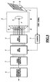
- Fig. 5 is a block diagram showing a configuration of the first embodiment in accordance with the present invention.
- the reference numeral 4 designates a peak detector for detecting peak values of the individual photo detectors D using a predetermined threshold. The intersection on the display surface F can be measured by obtaining the delay between the peak time and the time of a vertical sync signal.
- the reference numeral 5 designates a counter that is reset by the vertical sync signal of the display 1, and increments its count at every fixed period (or may count a predetermined time signal) to count time from the vertical sync signal. Its counting rate is determined such that it can detect the point of the electron beam on the display 1 at sufficiently high accuracy.
- the output of the counter 5 is supplied to AND gates 6.
- the reference numeral 7 designates a correspondence detector for bringing bright spot display positions on the display 1 at multiple timings into correspondence with projection image positions on the photo device 2 in accordance with their recording time.
- the reference numeral 8 designates an extrinsic parameter calculator for calculating the 3-D translation and rotation of the photo device 2 with respect to the bright spot scanning surface of the display 1 from a set of the multiple (at least three) bright spot display positions and their corresponding projection image positions.
- the foregoing components 5-8 constitute the 3D-position output module 3 of the present embodiment.
- the reference symbol N designates a projection plane and M designates a condense unit.
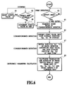
- Fig. 6 is a flowchart illustrating the operation of the first embodiment in accordance with the present invention. The operation will be described with reference to Fig. 6.
- the peak detector 4 detects a peak value of one of the photo detectors D (step S1).
- the position of the intersection on the screen can be obtained by obtaining the time delay of the time of the peak value from the time of vertical sync signal on the display surface F.
- the AND gates 6 are informed of the detection of the peak value.
- the counter 5 uses it as its reset signal and starts counting (step S3).
- the counter increments its count by one, and supplies its output to the AND gates 6 (step S4).
- the AND gates 6 supplies the count value to the correspondence detector 7 for each of the photo detectors D that detect the peak value (step S5).
- the correspondence detector 7 converts the count value to the spot display position (Xp, Yp) on the display 1 (step S6), and records the position (Xr, Yr) of the photo detector D that outputs the peak value and the spot display position (Xp, Yp) at that time (step S7).
- the extrinsic parameter calculator 8 can compute the translation and rotation of the photo device 2 from a set of (Xp, Yp, Xr, Yr) of at least three points and from the focal length f of the condense unit of the photo device 2 (step S8).
- a concrete method of the calculation method is described, for the three point calculation, in a paper by Koichiro Deguchi R. J. Holt and A. N. Netravali. "Camera calibration problem: Some new results. Computer Vision, Graphics, and Image Processing:" Image Understanding, Vol.54, No.3, PP.368-383, 1991. for example; and for the four point calculation, in a paper by Koichi Kato, et al.
- the position can be defined by the following translation matrix.
- Fig. 7 is a perspective view showing a second embodiment in accordance with the present invention, which employs a position sensitive light detector (PSD) 21 as a photo detector on the projection plane B of the photo device 2.
- PSD 21 consists of a silicon plate composed of three layer of P, I and N.
- P layer in this case
- the electrons pass through a resistance layer (P layer in this case) as photo electrons, and are output from the output terminal at the projection spot position (X, Y).
- the photo electrons are divided inversely proportional to the distance, that is, the resistance value, to electrodes, and are output from the output terminals at both ends.
- the position of incidence of the light can be obtained independently of the energy of photons.
- the position sensitive light detector 21 is disposed on the projection plane B.
- the display surface F is irradiated with the electron beam at every fixed period, and the high brightness spot moves thereon at a high speed as indicated by the arrow G.
- the position sensitive light detector 21 outputs the spot position (Xr, Yr) electrically.
- Fig. 8 is a block diagram showing a configuration of the second embodiment in accordance with the present invention.
- the reference numeral 9 designates a time-and-position detector that supplies the correspondence detector 7 with the spot light detection position and the count value of the counter 5 as (Xr, Yr, T).
- the remaining configuration is the same as that of Fig. 5.
- the components 5, 7, 8 and 9 constitute the 3D-position output module 3 of the present embodiment.
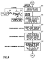
- Fig. 9 is a flowchart illustrating the operation of the second embodiment in accordance with the present invention. Referring to Fig. 9, the operation will be described in detail.
- step S11 When spot light is projected on the position sensitive light detector 21, it outputs the detection position (X, Y) of the spot, and transfers it to the time-and-position detector 9(step S11).
- step S12 detecting the vertical sync signal of the display 1 (step S12)
- the counter 5 uses the signal as its reset signal and starts counting (step S13).
- step S14 When detecting no sync signal, the counter 5 increments its count by one and supplies its output to the time-and-position detector 9 (step S14).
- the time-and-position detector 9 supplies the correspondence detector 7 with the detection position of the spot light and count value (Xr, Yr, T) (step S15).
- the correspondence detector 7 converts the count value T to the spot display position (Xp, Yp) on the display 1 (step S16), and records the position (Xr, Yr, T) of the photo detector outputting the peak value, and the spot display position (Xp, Yp) at that time (step S17).
- the extrinsic parameter calculator 8 calculates the translation and rotation of the photo device 2 from a set of (Xp, Yp, Xr, Yr) of at least three points and the focal length f of the condense unit of the photo device 2 (step S18).
- Fig. 10 is a perspective view showing a configuration of a photo device of a third embodiment in accordance with the present invention, which comprises multiple condense units and photo detectors to carry out wider range condense.
- the example as shown in Fig. 10 includes four sets of condense units and photo units disposed in such a manner that optical axes of the four sets intersect perpendicularly to each other, the number of the condense units and photo units, or the angles between the optical axes can be determined freely.
- the operation principle is the same as that of the foregoing first and second embodiments.
- Fig. 11 is a perspective view illustrating a fourth embodiment in accordance with the present invention.
- the present embodiment is a combination of the photo device used in the first and second embodiment with a device for converting 2-D movement into 2-D digital information such as a trackball, mouse or laser range finder.
- the example as shown in Fig. 11 integrates a 2-D information converter 10 consisting of a mouse with a photo device 11.
- Fig. 12 is a flowchart illustrating the operation of the fourth embodiment. Referring to this figure, the operation of the present embodiment will be described in detail.
- the operation of the present embodiment is the same as that of the first and second embodiments up to the stage that calculates the 3-D translation and rotation by the photo device 11 (step S21 - step S28). Subsequently, a decision is made as to whether the 2-D information converter 10 like a mouse is placed on a mouse pad 12 (step S29). When it is separated from the mouse pad, the 3-D translation and rotation is output, whereas when it is placed on the mouse pad, the moving information of the 2-D information converter 10 on the mouse pad 12 is detected and output (step S30).
- the single input device can share the function of a mouse that enables an image processing when moved on the mouse pad, and the function of the 3-D translation and rotation input device when suspended over the mouse pad, improving the operability.
- the photo device 2, 2-D information converter 10 and photo device 11 can increase their flexibility in movement by utilizing wireless transmission of their output signals as compared with using wired transmission.
- the scanning intervals can be varied and any scanning scheme can be employed as long as the correspondence between the ray projection point on the photo device and the position of the bright point on the display is uniquely determined.
- the photo device 2, 2-D information converter 10 and photo device 11 in the foregoing embodiments can be integrated into one body, and equipped with a means for wearing it on part of the body such as a hand, or for mounting it on a mobile unit such as a robot or vehicle, improving the operability.
- Figs. 5 and 8 can be implemented by a computer, and the procedures as shown in Figs. 6, 9 and 12 can also be carried out by a computer.
- Programs for implementing the functions of the components can be provided or distributed by recording them on a computer readable recording medium such as a FD (floppy disk), MO (magnet-optical disk), ROM, memory card, CD, DVD (digital video disk) or any other removable disks.
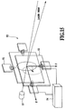
- Fig. 14 is a perspective view illustrating a fifth embodiment in accordance with the present invention.
- the reference numeral 41 designates a projection board
- 42 designates a photo device
- 43 designates a 3D-position output module
- 44 designates a lay-projection module.
- the present embodiment 5 is configured such that the lay-projection module 44 irradiates the surface of the projection board 41; the photo device 42 observes a figure or the like of scanning loci drawn on the surface; and the 3D-position output module 43 processes the observed information and scanning information, and outputs the translation and rotation of the photo device 42.
- Fig. 15 is a perspective view illustrating the lay-projection module 44 of the fifth embodiment in accordance with the present invention.
- the reference numeral 51 designates a magnetic circuit
- 52 designates a lens
- 53 designates a laser beam module
- 54 designates a control signal module.
- the lay-projection module 44 carries out any spatial laser scanning by a control method disclosed in Japanese Patent Application Laid-open No. 6-300542 (1994), titled "SHAPE FEATURE EXTRACTION DEVICE WITH TWO-DIMENSIONAL LASER PATTERN AND TWO-DIMENSIONAL LASER PATTERN".
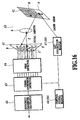
- Fig. 16 is a block diagram showing a configuration of the fifth embodiment in accordance with the present invention.
- the present embodiment 5 employs multiple photo detectors for converting the intensity of light into electric signals as the photo detectors of the photo device 42.
- the reference symbol A designates a lens
- B designates a projection plane of the light passing through the lens A
- C designates a center at which the optical axis of the lens intersects with the projection plane B
- D designates photo detectors
- F designates the display surface of the projection board irradiated by the laser
- 61 designates a display
- 62 designates a condense unit
- 63 designates the projection plane
- 64 designates a peak detector
- 65 designates a correspondence detector
- 66 designates an extrinsic parameter calculator
- 67(44) designates the lay-projection module
- 68(54) designates the control signal module.
- the photo detectors D are disposed on the projection plane.
- the display surface F is irradiated with the laser beam at every predetermined period such that the high brightness spot moves along the arrow G at high speed.
- the photo detector D outputs a peak.
- the peak detector 64 detects peak values of the individual photo detectors D.
- the correspondence detector 65 can determine the intersection on the screen by calculating the correspondence between the peak time and a control signal (x, y) transmitted from the control signal module 68 to the lay-projection module 67.
- the extrinsic parameter calculator 66 calculates the 3-D translation and rotation of the photo device with respect to the bright spot scanning surface of the display from a set consisting of multiple bright spot display positions and their projection positions.
- Fig. 17 is a flowchart illustrating the operation of the fifth embodiment in accordance with the present invention. Referring to this figure, the operation will be described in detail.
- the peak detector 64 detects the peak value of one of the photo detectors D (step S31).
- the correspondence detector 65 receives the laser scanning control signal (Xl, Yl) transmitted from the control signal module 68 shown in Fig. 16 (step S32).
- the correspondence detector 65 converts the laser scanning control signal into the spot display position (Xp, Yp) on the projection board (step S33), and records the position (Xr, Yr) of the photo detector D outputting the peak value, and the spot display position (Xp, Yp) at that time (step S34).
- the conversion from (Xl, Yl) to (Xp, Yp) is carried out using the following equations, in which case, the conversion coefficients a0 - a5 are obtained in advance.
- Xp a 0 ⁇ Xl + a 1 ⁇ Yl + a 2
- Yp a 3 ⁇ Xl + a 4 ⁇ Yl + a 5
- the extrinsic parameter calculator 66 can determine the translation and rotation of the photo device 42 from a set of (Xp, Yp, Xr, Yr) of at least three points and from the focal length of the condense unit 62 (step S35). In this case, the calculation of the 3-D translation and rotation of the photo device is carried out using the calculation method as illustrated in Fig. 6.
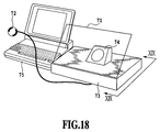
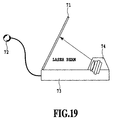
- Figs. 18 and 19 are views showing a sixth embodiment in accordance with the present invention: Fig. 18 is a perspective view showing the entire apparatus; and Fig. 19 is a side view of the apparatus.
- the reference numeral 71 designates a projection board
- 72 designates a photo device
- 73 designates a 3D-position output module
- 74 designates a lay-projection module
- 75 designates a personal computer.
- the projection board 71 is made translucent so that the bright spot of the laser light irradiated from the lay-projection module 74 undergoes diffused reflection on the bottom surface of the projection board 71 to display only the bright spot on the top surface of the projection board 71.
- the present apparatus supposes the 3-D input to a PC without a raster type display, and transmits the 3-D translation and rotation of the photo device 72 with respect to the projection board 71 to the personal computer 75 connected therewith.
- the perspective view of the lay-projection module, the block diagram showing the configuration and the flowchart illustrating the operation of the present embodiment are the same as those of the fifth embodiment as shown in Fig. 14.
Landscapes
- Engineering & Computer Science (AREA)
- General Engineering & Computer Science (AREA)
- Theoretical Computer Science (AREA)
- Human Computer Interaction (AREA)
- Physics & Mathematics (AREA)
- General Physics & Mathematics (AREA)
- Position Input By Displaying (AREA)
- Radiation Pyrometers (AREA)
- Electric Clocks (AREA)
Abstract
Description


Claims (32)
- An input device of 3-D translation and rotation for measuring 3-D translation and rotation of a photo device with respect to a display emitting a bright spot, said input device of 3-D translation and rotation characterized by comprising:a display with a display surface on which a bright spot is movable:a photo device including a condense unit for condensing a bright spot on said display to be projected onto a projection plane on which multiple photo detectors are disposed for detecting a projection position of the spot light on the projection plane;correspondence means for bringing a bright spot display position on said display into correspondence with a projection position of the spot light on said photo detectors; andan extrinsic parameter calculator for calculating the 3-D translation and rotation of said photo device with respect to the bright spot moving surface of said display from a set of multiple bright spot display positions and their projection positions which are brought into correspondence by said correspondence means.
- The input device of 3-D translation and rotation as claimed in claim 1, characterized in that said photo detectors for detecting the projection position of the spot light consist of a set of photo detectors, each of which includes a spot-like photo window.
- The input device of 3-D translation and rotation as claimed in claim 2, characterized in that said photo detectors with spot-like photo windows consist of three photo detectors, and the bright spot display positions and the projection positions, which are brought into correspondence by said correspondence means, have three positions, each.
- The input device of 3-D translation and rotation as claimed in claim 2, characterized in that said photo detectors with spot-like photo windows consist of at least five photo detectors, and the bright spot display positions and the projection positions, which are brought into correspondence by said correspondence means, have at least five positions, each.
- The input device of 3-D translation and rotation as claimed in claim 2, characterized in that said correspondence means comprises:means for bringing a projection image position on said photo detectors into correspondence with projection time, the projection image position being a position formed by projecting the bright spot on said display onto the projection plane of said photo device;means for recording the projection position and projection time; anda correspondence detector for bringing bright spot display positions at multiple times into correspondence with their projection positions in accordance with the recorded projection time.
- The input device of 3-D translation and rotation as claimed in claim 2, characterized in that said display carries out scanning and display of the bright spot.
- The input device of 3-D translation and rotation as claimed in claim 6, characterized in that said display employs a CRT display for carrying out scanning and display of the bright spot.
- The input device of 3-D translation and rotation as claimed in claim 6, characterized in that said display employs a ray projection device and projection board for carrying out scanning and display of the bright spot.
- The input device of 3-D translation and rotation as claimed in claim 2, characterized in that said photo device comprises multiple sets of condense units and projection planes, said multiple sets having different optical axes.
- The input device of 3-D translation and rotation as claimed in claim 2, characterized in that said photo device comprises means for mounting it on a mobile unit such as a robot and vehicle, or for wearing it on part of a body, or for holding it by part of the body.
- The input device of 3-D translation and rotation as claimed in claim 2, characterized in that said photo device is combined with a device for converting 2-D movement into digital 2-D information.
- The input device of 3-D translation and rotation as claimed in claim 11, characterized in that said device for converting consists of one of a trackball, a mouse and a laser range finder.
- The input device of 3-D translation and rotation as claimed in claim 2, characterized in that said photo device is made freely movable by utilizing one of wired and wireless transmission of its output signal.
- The input device of 3-D translation and rotation as claimed in claim 1, characterized in that said photo detectors for detecting the projection position of the spot light consist of a photo detector including a flat photo detecting face for detecting the position of the spot light.
- The input device of 3-D translation and rotation as claimed in claim 13, characterized in that said correspondence means comprises:means for bringing a projection image position of the spot light on said photo detectors into correspondence with projection time, the projection image position of the spot light being a position formed by projecting the bright spot on said display onto the projection plane of said photo device;means for recording the projection position and projection time; anda correspondence detector for bringing bright spot display positions at multiple times into correspondence with their projection positions in accordance with the recorded projection time.
- The input device of 3-D translation and rotation as claimed in claim 14, characterized in that said photo device consists of a position sensitive light detector.
- The input device of 3-D translation and rotation as claimed in claim 14, characterized in that said display carries out scanning and display of the bright spot.
- The input device of 3-D translation and rotation as claimed in claim 17, characterized in that said display employs a CRT display for carrying out scanning and display of the bright spot.
- The input device of 3-D translation and rotation as claimed in claim 17, characterized in that said display employs a ray projection device and projection board for carrying out scanning and display of the bright spot.
- The input device of 3-D translation and rotation as claimed in claim 14, characterized in that said photo device comprises multiple sets of condense units and projection planes, said multiple sets having different optical axes.
- The input device of 3-D translation and rotation as claimed in claim 14, characterized in that said photo device comprises means for mounting it on a mobile unit such as a robot and vehicle, or for wearing it on part of a body, or for holding it by part of the body.
- The input device of 3-D translation and rotation as claimed in claim 14, characterized in that said photo device is combined with a device for converting 2-D movement into digital 2-D information.
- The input device of 3-D translation and rotation as claimed in claim 22, characterized in that said device for converting consists of one of a trackball, a mouse and a laser range finder.
- The input device of 3-D translation and rotation as claimed in claim 13, characterized in that said photo device is made freely movable by utilizing one of wired and wireless transmission of its output signal.
- An input method of 3-D translation and rotation for measuring 3-D translation and rotation of a photo device with respect to a display emitting a bright spot, said input method of 3-D translation and rotation characterized by comprising the steps of:moving the bright spot freely on a display surface of said display:condensing the bright spot on said display, and detecting a projection position of the spot light projected onto a projection plane;bringing a bright spot display position on said display into correspondence with the projection position of the spot light on photo detectors; andcalculating the 3-D translation and rotation of said photo device with respect to the bright spot moving surface of said display from a set of multiple bright spot display positions and their projection positions which are brought into correspondence.
- The input method of 3-D translation and rotation as claimed in claim 25, characterized in that said photo detectors for detecting the projection position of the spot light consist of a set of photo detectors, each of which includes a spot-like photo window.
- The input method of 3-D translation and rotation as claimed in claim 26, characterized in that the step of bringing comprises the sub-steps of:bringing a projection image position on said photo detectors into correspondence with projection time, the projection image position being a position formed by projecting the bright spot on said display onto the projection plane of said photo device;recording the projection position and projection time; andbringing bright spot display positions at multiple times into correspondence with their projection positions in accordance with the recorded projection time.
- The input method of 3-D translation and rotation as claimed in claim 25, characterized in that said photo detectors for detecting the projection position of the spot light consist of a photo detector including a flat photo detecting face for detecting the position of the spot light.
- The input method of 3-D translation and rotation as claimed in claim 28, characterized in that the step of bringing comprises the sub-steps of:bringing a projection image position of the spot light on said photo detectors into correspondence with projection time, the projection image position of the spot light being a position formed by projecting the bright spot on said display onto the projection plane of said photo device;recording the projection position and projection time; andbringing bright spot display positions at multiple times into correspondence with their projection positions in accordance with the recorded projection time.
- A computer readable recording medium for causing a computer to execute an input method of 3-D translation and rotation for measuring 3-D translation and rotation of a photo device with respect to a display emitting a bright spot, said computer readable recording medium causes the computer to execute the steps of:moving the bright spot freely on a display surface of said display;condensing the bright spot on said display, and detecting a projection position of the spot light projected onto a projection plane;bringing a bright spot display position on said display into correspondence with the projection position of the spot light on photo detectors; andcalculating the 3-D translation and rotation of said photo device with respect to the bright spot moving surface of said display from a set of multiple bright spot display positions and their projection positions which are brought into correspondence.
- The recording medium as claimed in claim 30, characterized in that said photo detectors for detecting the projection position of the spot light consist of a set of photo detectors, each of which includes a spot-like photo window, and characterized in that the step of bringing comprises the sub-steps of:bringing a projection image position on said photo detectors into correspondence with projection time, the projection image position being a position formed by projecting the bright spot on said display onto the projection plane of said photo device;recording the projection position and projection time; andbringing bright spot display positions at multiple times into correspondence with their projection positions in accordance with the recorded projection time.
- The recording medium as claimed in claim 30, characterized in that the spot light on said photo detectors at the step of bringing is the spot light detected and output from said photo detectors, and characterized in that the step of bringing comprises the sub-steps of:bringing a projection image position of the spot light on said photo detectors into correspondence with projection time, the projection image position of the spot light being a position formed by projecting the bright spot on said display onto the projection plane of said photo device;recording the projection position and projection time; andbringing bright spot display positions at multiple times into correspondence with their projection positions in accordance with the recorded projection time.
Applications Claiming Priority (2)
| Application Number | Priority Date | Filing Date | Title |
|---|---|---|---|
| JP28367099 | 1999-10-05 | ||
| JP28367099 | 1999-10-05 |
Publications (2)
| Publication Number | Publication Date |
|---|---|
| EP1091315A2 true EP1091315A2 (en) | 2001-04-11 |
| EP1091315A3 EP1091315A3 (en) | 2004-02-04 |
Family
ID=17668552
Family Applications (1)
| Application Number | Title | Priority Date | Filing Date |
|---|---|---|---|
| EP00121789A Withdrawn EP1091315A3 (en) | 1999-10-05 | 2000-10-05 | Input device for 3-D translation and rotation of an image |
Country Status (3)
| Country | Link |
|---|---|
| US (2) | US6710765B1 (en) |
| EP (1) | EP1091315A3 (en) |
| CA (1) | CA2322244C (en) |
Families Citing this family (4)
| Publication number | Priority date | Publication date | Assignee | Title |
|---|---|---|---|---|
| US6710765B1 (en) * | 1999-10-05 | 2004-03-23 | Nippon Telegraph And Telephone Corporation | Input device of 3-D translation and rotation and its method and recording medium |
| US6873924B1 (en) * | 2003-09-30 | 2005-03-29 | General Electric Company | Method and system for calibrating relative fields of view of multiple cameras |
| US8521411B2 (en) * | 2004-06-03 | 2013-08-27 | Making Virtual Solid, L.L.C. | En-route navigation display method and apparatus using head-up display |
| CN105183318A (en) * | 2015-09-08 | 2015-12-23 | 闫维新 | Non-contact type interaction device based on screen or projection |
Family Cites Families (20)
| Publication number | Priority date | Publication date | Assignee | Title |
|---|---|---|---|---|
| US5432526A (en) * | 1970-12-28 | 1995-07-11 | Hyatt; Gilbert P. | Liquid crystal display having conductive cooling |
| US5237647A (en) * | 1989-09-15 | 1993-08-17 | Massachusetts Institute Of Technology | Computer aided drawing in three dimensions |
| US5546327A (en) * | 1990-12-27 | 1996-08-13 | Matsushita Electric Industrial Co., Ltd. | Apparatus for calculating geometrical view factor |
| US5227985A (en) * | 1991-08-19 | 1993-07-13 | University Of Maryland | Computer vision system for position monitoring in three dimensions using non-coplanar light sources attached to a monitored object |
| JP3263724B2 (en) | 1993-04-16 | 2002-03-11 | 日本電信電話株式会社 | Shape feature extraction device using two-dimensional laser pattern |
| JP3315240B2 (en) | 1994-03-30 | 2002-08-19 | 日本電信電話株式会社 | Imaging system parameter measurement method and device |
| ATE261150T1 (en) * | 1994-06-09 | 2004-03-15 | Corp For Nat Res Initiatives | NOTIFICATION DEVICE INTERFACE |
| US5796387A (en) * | 1994-08-16 | 1998-08-18 | Smith Engineering | Positioning system using infrared radiation |
| US5805196A (en) * | 1994-09-09 | 1998-09-08 | Konica Corporation | Apparatus for recording a color image on a color photogaphic material based on three color component image signals separated from the color image |
| JP3138396B2 (en) | 1994-10-26 | 2001-02-26 | 株式会社ナムコ | Image display device and shooting type game device |
| JPH08278846A (en) | 1995-02-10 | 1996-10-22 | Data Tec:Kk | Three-dimensional data input device |
| US5633691A (en) * | 1995-06-07 | 1997-05-27 | Nview Corporation | Stylus position sensing and digital camera with a digital micromirror device |
| JP3190238B2 (en) * | 1995-10-31 | 2001-07-23 | シャープ株式会社 | Active matrix liquid crystal panel defect detection method |
| JP3299441B2 (en) * | 1996-06-06 | 2002-07-08 | 日本電信電話株式会社 | 3D position / posture measuring device |
| FR2768528B1 (en) * | 1997-09-18 | 2001-01-12 | Aerospatiale | COMPUTER INPUT DEVICE, AUTOMATICALLY SWITCHED BETWEEN 3D AND 2D OPERATING MODES, AND ITS INTERACTION METHOD WITH A DISPLAY SCREEN |
| EP0911720A1 (en) | 1997-10-23 | 1999-04-28 | Hewlett-Packard Company | User input device |
| JP3492180B2 (en) | 1998-01-30 | 2004-02-03 | キヤノン株式会社 | Coordinate input device |
| US6064423A (en) * | 1998-02-12 | 2000-05-16 | Geng; Zheng Jason | Method and apparatus for high resolution three dimensional display |
| JPH11296127A (en) * | 1998-04-07 | 1999-10-29 | Hitachi Ltd | Liquid crystal display |
| US6710765B1 (en) * | 1999-10-05 | 2004-03-23 | Nippon Telegraph And Telephone Corporation | Input device of 3-D translation and rotation and its method and recording medium |
-
2000
- 2000-10-03 US US09/678,274 patent/US6710765B1/en not_active Expired - Lifetime
- 2000-10-04 CA CA002322244A patent/CA2322244C/en not_active Expired - Fee Related
- 2000-10-05 EP EP00121789A patent/EP1091315A3/en not_active Withdrawn
-
2003
- 2003-12-05 US US10/728,997 patent/US7253801B2/en not_active Expired - Fee Related
Also Published As
| Publication number | Publication date |
|---|---|
| US7253801B2 (en) | 2007-08-07 |
| US20040113889A1 (en) | 2004-06-17 |
| EP1091315A3 (en) | 2004-02-04 |
| CA2322244A1 (en) | 2001-04-05 |
| CA2322244C (en) | 2005-12-13 |
| US6710765B1 (en) | 2004-03-23 |
Similar Documents
| Publication | Publication Date | Title |
|---|---|---|
| US8971565B2 (en) | Human interface electronic device | |
| US7557935B2 (en) | Optical coordinate input device comprising few elements | |
| CN101019096B (en) | Apparatus and method for detecting a pointer relative to a touch surface | |
| US4965442A (en) | System for ascertaining direction of blur in a range-from-defocus camera | |
| US20020085097A1 (en) | Computer vision-based wireless pointing system | |
| US5793357A (en) | Device and method for determining movement of a surface | |
| TWI454993B (en) | Imaging device based touch system | |
| EP0829798A2 (en) | Image-based touchscreen | |
| JPH08506193A (en) | Device and method for diffusion-assisted localization for visual detection of pens | |
| KR20080044017A (en) | touch screen | |
| CA2253085A1 (en) | Methods and system for measuring three dimensional spatial coordinates and for external camera calibration necessary for that measurement | |
| JPH04115108A (en) | Three-dimensional scanner | |
| WO2018161542A1 (en) | 3d touch interaction device and touch interaction method thereof, and display device | |
| JP2021518020A (en) | Depth processor and 3D imaging equipment | |
| KR101207877B1 (en) | Apparatus of coordinates cognition and method of cognizing coordinates | |
| CA2322244C (en) | Input device of 3-d translation and rotation and its method and recording medium | |
| Wallace et al. | 3D imaging and ranging by time-correlated single photon counting | |
| JP4114637B2 (en) | Position measurement system | |
| CN112683198A (en) | Three-degree-of-freedom angle photoelectric measuring device and measuring method thereof | |
| JP3523583B2 (en) | Three-dimensional position / posture measuring apparatus and method, and recording medium | |
| JP2681745B2 (en) | A method for measuring the vertical and lateral movement of an object to be measured with a speckle pattern using laser light. | |
| Latoschik et al. | Augmenting a laser pointer with a diffraction grating for monoscopic 6dof detection | |
| JP3196861B2 (en) | Object position detection method and object position detection device | |
| JP2731681B2 (en) | 3D measurement system | |
| JP2002163071A (en) | Photo detector |
Legal Events
| Date | Code | Title | Description |
|---|---|---|---|
| PUAI | Public reference made under article 153(3) epc to a published international application that has entered the european phase |
Free format text: ORIGINAL CODE: 0009012 |
|
| AK | Designated contracting states |
Kind code of ref document: A2 Designated state(s): AT BE CH CY DE DK ES FI FR GB GR IE IT LI LU MC NL PT SE |
|
| AX | Request for extension of the european patent |
Free format text: AL;LT;LV;MK;RO;SI |
|
| PUAL | Search report despatched |
Free format text: ORIGINAL CODE: 0009013 |
|
| AK | Designated contracting states |
Kind code of ref document: A3 Designated state(s): AT BE CH CY DE DK ES FI FR GB GR IE IT LI LU MC NL PT SE |
|
| AX | Request for extension of the european patent |
Extension state: AL LT LV MK RO SI |
|
| 17P | Request for examination filed |
Effective date: 20040503 |
|
| AKX | Designation fees paid |
Designated state(s): DE FR GB |
|
| APBK | Appeal reference recorded |
Free format text: ORIGINAL CODE: EPIDOSNREFNE |
|
| APBN | Date of receipt of notice of appeal recorded |
Free format text: ORIGINAL CODE: EPIDOSNNOA2E |
|
| APBR | Date of receipt of statement of grounds of appeal recorded |
Free format text: ORIGINAL CODE: EPIDOSNNOA3E |
|
| APAF | Appeal reference modified |
Free format text: ORIGINAL CODE: EPIDOSCREFNE |
|
| APBT | Appeal procedure closed |
Free format text: ORIGINAL CODE: EPIDOSNNOA9E |
|
| STAA | Information on the status of an ep patent application or granted ep patent |
Free format text: STATUS: THE APPLICATION IS DEEMED TO BE WITHDRAWN |
|
| 18D | Application deemed to be withdrawn |
Effective date: 20160301 |