EP1091203B1 - Process and device for measuring particles of a tobacco particle stream - Google Patents
Process and device for measuring particles of a tobacco particle stream Download PDFInfo
- Publication number
- EP1091203B1 EP1091203B1 EP00117364A EP00117364A EP1091203B1 EP 1091203 B1 EP1091203 B1 EP 1091203B1 EP 00117364 A EP00117364 A EP 00117364A EP 00117364 A EP00117364 A EP 00117364A EP 1091203 B1 EP1091203 B1 EP 1091203B1
- Authority
- EP
- European Patent Office
- Prior art keywords
- particles
- particle
- set forth
- tobacco
- fine
- Prior art date
- Legal status (The legal status is an assumption and is not a legal conclusion. Google has not performed a legal analysis and makes no representation as to the accuracy of the status listed.)
- Expired - Lifetime
Links
Images


Classifications
-
- G—PHYSICS
- G01—MEASURING; TESTING
- G01N—INVESTIGATING OR ANALYSING MATERIALS BY DETERMINING THEIR CHEMICAL OR PHYSICAL PROPERTIES
- G01N15/00—Investigating characteristics of particles; Investigating permeability, pore-volume, or surface-area of porous materials
- G01N15/02—Investigating particle size or size distribution
-
- A—HUMAN NECESSITIES
- A24—TOBACCO; CIGARS; CIGARETTES; SIMULATED SMOKING DEVICES; SMOKERS' REQUISITES
- A24B—MANUFACTURE OR PREPARATION OF TOBACCO FOR SMOKING OR CHEWING; TOBACCO; SNUFF
- A24B1/00—Preparation of tobacco on the plantation
- A24B1/04—Sifting, sorting, cleaning or removing impurities from tobacco
-
- A—HUMAN NECESSITIES
- A24—TOBACCO; CIGARS; CIGARETTES; SIMULATED SMOKING DEVICES; SMOKERS' REQUISITES
- A24C—MACHINES FOR MAKING CIGARS OR CIGARETTES
- A24C5/00—Making cigarettes; Making tipping materials for, or attaching filters or mouthpieces to, cigars or cigarettes
- A24C5/32—Separating, ordering, counting or examining cigarettes; Regulating the feeding of tobacco according to rod or cigarette condition
- A24C5/34—Examining cigarettes or the rod, e.g. for regulating the feeding of tobacco; Removing defective cigarettes
- A24C5/3412—Examining cigarettes or the rod, e.g. for regulating the feeding of tobacco; Removing defective cigarettes by means of light, radiation or electrostatic fields
-
- A—HUMAN NECESSITIES
- A24—TOBACCO; CIGARS; CIGARETTES; SIMULATED SMOKING DEVICES; SMOKERS' REQUISITES
- A24C—MACHINES FOR MAKING CIGARS OR CIGARETTES
- A24C5/00—Making cigarettes; Making tipping materials for, or attaching filters or mouthpieces to, cigars or cigarettes
- A24C5/39—Tobacco feeding devices
- A24C5/396—Tobacco feeding devices with separating means, e.g. winnowing, removing impurities
-
- G—PHYSICS
- G01—MEASURING; TESTING
- G01N—INVESTIGATING OR ANALYSING MATERIALS BY DETERMINING THEIR CHEMICAL OR PHYSICAL PROPERTIES
- G01N15/00—Investigating characteristics of particles; Investigating permeability, pore-volume, or surface-area of porous materials
- G01N2015/0042—Investigating dispersion of solids
- G01N2015/0046—Investigating dispersion of solids in gas, e.g. smoke
- G01N2015/0049—Investigating dispersion of solids in gas, e.g. smoke of filaments in gas
-
- G—PHYSICS
- G01—MEASURING; TESTING
- G01N—INVESTIGATING OR ANALYSING MATERIALS BY DETERMINING THEIR CHEMICAL OR PHYSICAL PROPERTIES
- G01N15/00—Investigating characteristics of particles; Investigating permeability, pore-volume, or surface-area of porous materials
- G01N15/02—Investigating particle size or size distribution
- G01N2015/0294—Particle shape
Definitions
- DE 37 06 502 shows a device for determining the particle size distribution pulverulent material with two measuring cells, which alternately in the beam path of a Laser beam can be introduced.
- a measuring cell stands for the Operation while simultaneously cleaning the second measuring cell can.
- DE 28 55 583 C2 shows a method for determining the particle size distribution of grain mixtures statically registered by means of a television camera and the data in Depending on the statically projected images of the falling grains processed become.
- calibration measurements on a sieved grain class from the Grain mixture performed and assuming that the grains take the form of a Rotational ellipsoids have a mean configuration coefficient as the mean value of the Ratio of the long axis to the short axis of the grains determined.
- DE 43 07 407 C2 still shows a device for the production of Cigarettes, in which the light tobacco particles from the waste material with the heavier tobacco particles are separated. A monitoring of the quality of Separation by means of a suitable sensor is not addressed.
- the advantages achieved by the invention are based on an optical method that works by means of a fine-beam photoelectric sensor and from the darkening of the light beam the fine beam photoelectric sensor has a mean dimension and an average volume of Winnowings particles determined on the basis of statistical considerations.
- This measurement primarily provides information about the particle size distribution because of the individual particles are measured separately. From this, the middle one becomes continuously Dimension, the mean volume, the average particle mass and the Particle mass flow determined.
- the measured value for the mass flow determined in this way is independent of the conveying speed of the Winnowings stream, as the particle velocity, for example by using a second fine-beam photoelectric sensor, measured directly in the device and used in the calculation of the just mentioned quantities. This way will also takes into account the slip of particles in the flow, and the meter becomes self-sufficient, independent of other sensors.
- the optical measuring method does not lead to any additional degradation of the winnowing current, because the sensor operates without contact and bumpless without cross section change can be inserted directly into an existing production pipe, directly as a sensor pipe can serve.
- the radius R of the tube is compared with the dimensions of the winnowing particles very large.
- a location-dependent response probability w A (x) of the light barrier which is shown in FIG. 2c, takes the place of the detection area. It is obtained by averaging over all orientations.
- time duration ⁇ i of a single light barrier signal depends on the exact puncture position x i of the path of the detected particle through the sensor plane and on the size and angular orientation of the particle.
- the Winnowings product stream is scanned with the aid of two fine-beam photoelectric sensors, which are mounted in a short distance b 12 in succession in the sensor tube, see Fig. 3.
- the time difference t 12 v ⁇ b12 of the signals 1. and the second fine beam photoelectric sensor is evaluated, it is thus possible to determine the particle velocity v directly in the sensor itself. This makes the particle sensor self-sufficient, independent of other measuring devices.
- the operating principle of the sensor requires that the laser beams of the two Photocells in the direction of flight are as thin as possible, so that the particle size with good Accuracy can be measured. This is by using a carefully focused Gaussian beam possible.
Abstract
Description
Die Erfindung betrifft ein Verfahren und eine Vorrichtung zur Erfassung der Partikel eines Tabakpartikel-Stroms bei der Herstellung von rauchbaren Artikeln, insbesondere von Winnowings.The invention relates to a method and a device for detecting the particles of a tobacco particle stream in the manufacture of smokable articles, in particular winnowings.
Bei der Cigarettenherstellung erfolgt in der Cigarettenmaschine eine Sichtung des ankommenden Tabakstroms. Nur hinreichend feines Material wird in den Strang eingebaut. Der verbleibende Anteil gröberen Materials, die sogenannten "Winnowings", wird durch den Sichtprozess abgeschieden und per Luftförderung für die weitere Verarbeitung zentral gesammelt.When making cigarettes in the cigarette machine, a sighting of the incoming tobacco stream. Only sufficiently fine material is in the strand built-in. The remaining proportion of coarser material, the so-called "winnowings", is separated by the visual process and by air for the further Processing collected centrally.
Für die Betriebsoptimierung der Cigarettenmaschine ist es wichtig, den Massenstrom von Winnowings an und im Betrieb der Cigarettenherstellungsmaschine sowie die Größenverteilung der Winnowings online zu bestimmen und die gewonnenen Parameter zur Justierung der Ausselektion der Winnowings zu nutzen. Bisher wurde die Erfassung der Winnowings nicht an der Cigarettenmaschine durchgeführt, sondern, wenn überhaupt, offline durch Siebanalysen der ausgeschiedenen Winnowings. Das resultierende Messergebnis kann dann dazu dienen, die Sichtungsbedingungen online im Hinblick auf möglichst hohe Produktqualität (Ausschleusung möglichst aller Winnowings) bei Abscheidung von ausschließlich Winnowings zu optimieren. Eine raschere und flexiblere Optimierung wäre gegeben, wenn die Analyse des Winnowing-Massenstromes online möglich wäre unmittelbar am Winnowing-Ausgang der Cigarettenmaschine. Diese Messung des Massenstroms muss bei variabler Geschwindigkeit des Förderluftstroms erfolgen, damit die Funktion auch bei sich ändernden Betriebsparametern der Cigarettenmaschine gewährleistet ist, und die Genauigkeit des Messergebnisses sollte unabhängig von Schwankungen der Winnowings-Partikelgrößen sein.For the operational optimization of the cigarette machine, it is important to control the mass flow of Winnowings and in the operation of the cigarette making machine as well as the Size distribution of winnowings online to determine and the parameters obtained to adjust for the selection of the winnowings. So far, the capture has been Winnowings was not performed on the cigarette machine, but, if anything, offline through sieve analyzes of the departed Winnowings. The resulting Measurement result can then serve the viewing conditions online with regard to the highest possible product quality (discharge of all possible winnowings) Separation of only winnowings to optimize. A faster and more flexible Optimization would be given if the analysis of the Winnowing mass flow online possible would be directly at the Winnowing output of the cigarette maker. These Measurement of mass flow must be at variable speed of the conveying air flow be carried out so that the function even with changing operating parameters of the Cigarette machine is guaranteed, and the accuracy of the measurement result should be regardless of fluctuations in winnowings particle sizes.
Darüber hinaus ist es im Sinne der laufenden Prozessüberwachung interessant, aus dem Winnowings-Teilchenstrom Informationen über die momentane Größenverteilung zu erhalten, etwa über die mittlere Partikelgröße und die Streubreite der Größenverteilung, um Störungen des Sichtungsprozesses schnell und selektiv erkennen zu können.Moreover, it is interesting in the sense of ongoing process monitoring, from the Winnowings particle current information about the current size distribution too about the mean particle size and the spread of the size distribution, to be able to recognize disturbances of the viewing process quickly and selectively.
Dies ist mit den bisher eingesetzten offline Siebanalysen per definitionem nicht möglich.This is by definition not possible with the previously used offline sieve analyzes.
Auf anderen technischen Gebieten außerhalb der Cigarettenherstellung sind bereits verschiedene optische Sichtungsverfahren entwickelt worden. So zeigt die DE-41 19 240 C2 ein Verfahren zur Bestimmung der Partikelgrößenverteilung eines Partikelgemisches bei dem die einzelnen Partikel Kugelform haben. Dabei wird das Partikelgemisch an einer optoelektronischen Meßstrecke senkrecht zu einem parallelen Lichtstrahl vorbeibewegt und zeilenweise optoelektronisch abgetastet, wodurch die Sehnenlängen der Partikel gemessen und mit einem Klassifikator bestimmte Längenklassen zugeordnet werden; daraus wird die Partikelgrößenverteilung nach Partikelgrößenklassen berechnet, die nach den Partikeldurchmessern der entsprechenden Längenklassen festgelegt werden.In other technical fields outside of cigarette manufacturing are already Various optical screening methods have been developed. That's how it shows DE-41 19 240 C2 a method for determining the particle size distribution of a Particle mixture in which the individual particles have spherical shape. This is the Particle mixture on an opto-electronic test section perpendicular to a parallel Passed light beam and line by line optoelectronically scanned, causing the Chord lengths of particles measured and determined with a classifier Length classes are assigned; From this the particle size distribution becomes Particle size classes calculated according to the particle diameters of the corresponding Length classes are set.
Aufgrund der von der Kugelform stark abweichenden Formen der Winnowings lässt sich dieses Verfahren nicht zur Sichtung von Tabakteilchen einsetzen.Due to the shape of the winnowing, which differs greatly from the spherical shape, it is possible to Do not use this procedure to inspect tobacco particles.
Die DE 32 36 261 beschreibt ein Verfahren zum Ermitteln des durchschnittlichen Radius und/oder der durchschnittlichen Länge von in einem Strömungsmittel beförderten Teilchen, die durch zwei Schlitze einer Maske fliegen. Die Strahlung, die durch die Partikel emittiert, gestreut oder absorbiert wird, wenn sie diese Schlitze durchsetzen, wird überwacht, wodurch bestimmte Partikel identifiziert werden können, die vollständig durch beide Schlitze hindurchtreten. Auch dieses Verfahren ist aufgrund der unregelmäßigen Formen der Tabak-Winnowings nicht für die Sichtung von Tabakteilchen geeignet.DE 32 36 261 describes a method for determining the average radius and / or the average length of carried in a fluid Particles flying through two slits of a mask. The radiation passing through the Particles are emitted, scattered or absorbed as they pass through these slots, is monitored, whereby certain particles can be completely identified pass through both slots. Also this procedure is due to the irregular forms of tobacco winnowings not for the screening of tobacco particles suitable.
Aus der DE 197 06 890 A geht ein ähnliches Verfahren hervor, wobei diejenigen Partikel identifiziert werden, für welche die emittierte, gestreute oder absorbierte Strahlung eine vorbestimmte Beziehung hat; die Größe der identifizierten Partikel wird aus der Menge der emittierten, gestreuten oder absorbierten Strahlen ermittelt, wenn die identifizierten Partikel durch die Schlitze hindurchtreten.DE 197 06 890 A discloses a similar process, wherein those particles be identified, for which the emitted, scattered or absorbed radiation a has predetermined relationship; The size of the identified particles will be out of the set the emitted, scattered or absorbed rays, if identified Particles pass through the slots.
Die DE 37 06 502 zeigt eine Vorrichtung zur Bestimmung der Kornverteilung bei pulverförmigem Gut mit zwei Messzellen, die wechselweise in den Strahlengang eines Laserstrahls eingeführt werden können. Auf diese Weise steht eine Messzelle für den Betrieb zur Verfügung, während gleichzeitig die zweite Messzelle gereinigt werden kann.DE 37 06 502 shows a device for determining the particle size distribution pulverulent material with two measuring cells, which alternately in the beam path of a Laser beam can be introduced. In this way, a measuring cell stands for the Operation while simultaneously cleaning the second measuring cell can.
Die DE 42 15 908 A offenbart ein optisches Partikelmessverfahren für die Reinraumüberwachung und zur Kontrolle hochreiner Flüssigkeit, wobei die durch ein Messvolumen geleiteten Partikel bestrahlt werden und eine Abbildungseinrichtung mit Detektor das dabei entstehende Streulicht ermittelt; die Strahlung für das Messvolumen wird derart moduliert, dass sich ein zeitlich moduliertes Messsignal ergibt, wodurch eine Verbesserung des Verhältnisses Signal/Rauschen möglich wird.DE 42 15 908 A discloses an optical particle measuring method for the Clean room monitoring and control of highly pure liquid, whereby by a Measuring volume guided particles are irradiated and an imaging device with Detector detects the resulting scattered light; the radiation for the measuring volume is modulated in such a way that results in a time-modulated measurement signal, whereby a Improvement of the signal / noise ratio is possible.
Die DE 28 55 583 C2 zeigt ein Verfahren zur Bestimmung der Korngrößenverteilung von Korngemischen, die mittels einer Fernsehkamera statisch registriert und die Daten in Abhängigkeit von den statisch projizierten Bilder der fallenden Körner verarbeitet werden. Dabei werden Eichmessungen an einer herausgesiebten Kornklasse aus dem Korngemisch durchgeführt und unter der Annahme, dass die Körner die Gestalt eines Rotationsellipsoids haben, ein mittlerer Konfigurationskoeffizient als mittlerer Wert des Verhältnisses der langen Achse zur kurzen Achse der Körner ermittelt. Auch diese Annahme einer rotationsellipsoiden Form lässt sich bei Tabakteilchen nicht einsetzen.DE 28 55 583 C2 shows a method for determining the particle size distribution of grain mixtures statically registered by means of a television camera and the data in Depending on the statically projected images of the falling grains processed become. In this case, calibration measurements on a sieved grain class from the Grain mixture performed and assuming that the grains take the form of a Rotational ellipsoids have a mean configuration coefficient as the mean value of the Ratio of the long axis to the short axis of the grains determined. These too Assumption of a rotationally ellipsoidal form can not be used with tobacco particles.
Die DE 32 16 486 zeigt einen Detektor für den abgeschnittenen Tabaküberschuss bei der Cigarettenherstellung. Der gesamte Tabaküberschuss wird pneumatisch durch den Detektor geführt, dessen Lichtstrahl durch den Tabakstrom ähnlich wie ein Schirm gedämpft wird. Die Stärke des durch die Fotozellen des Detektors erzeugten Stroms ist also umgekehrt proportional zur Dichte des Tabakstroms und damit zum Durchsatz des Tabaks. Die Erfassung einzelner Tabakteilchen ist nicht möglich.DE 32 16 486 shows a detector for the cut tobacco excess in the Cigarette production. The entire tobacco surplus is pneumatically by the Detector guided, whose light beam through the tobacco stream similar to a screen is dampened. The strength of the current generated by the photocells of the detector is thus inversely proportional to the density of the tobacco stream and thus to the throughput of the Tobacco. The detection of individual tobacco particles is not possible.
Schließlich zeigt die DE 43 07 407 C2 noch eine Vorrichtung zur Herstellung von Cigaretten, bei der die leichten Tabakpartikel von dem Abfallmaterial mit den schwereren Tabakpartikeln getrennt werden. Eine Überwachung der Qualität der Trennung mittels eines geeigneten Sensors wird nicht angesprochen.Finally, DE 43 07 407 C2 still shows a device for the production of Cigarettes, in which the light tobacco particles from the waste material with the heavier tobacco particles are separated. A monitoring of the quality of Separation by means of a suitable sensor is not addressed.
Der Erfindung liegt die Aufgabe zugrunde, ein Verfahren und eine Vorrichtung zur Erfassung des Massenstromes der Partikel eines Winnowings-Stroms bei der Herstellung von rauchbaren Artikeln zu schaffen, bei dem die Nachteile der nachträglichen Siebanalysen vermieden werden. Insbesondere soll ein Verfahren vorgeschlagen werden, das online arbeitet und damit zur Optimierung der Sichtungsbedingungen im Hinblick auf Produktqualität und die Abscheidung von ausschließlich Winnowings eingesetzt werden kann.The invention is based on the object, a method and an apparatus for detecting the Mass flow of the particles of a Winnowings-stream in the production of smokable articles, with the disadvantages of the subsequent sieve analysis be avoided. In particular, a method should be proposed online works and thus to optimize the viewing conditions with regard to Product quality and the separation of only winnowings are used can.
Diese Aufgabe wird erfindungsgemäß durch die in den Ansprüchen 1 bzw. 22 angegebenen Merkmale gelöst.This object is achieved by the features specified in claims 1 and 22, respectively solved.
Zweckmäßige Ausführungsformen werden durch die Merkmale der Unteransprüche definiert.Advantageous embodiments are characterized by the features of the subclaims Are defined.
Die mit der Erfindung erzielten Vorteile beruhen auf einem optischen Verfahren, das mittels einer Feinstrahl-Lichtschranke arbeitet und aus der Abdunklung des Lichtstrahls der Feinstrahl-Lichtschranke eine mittlere Abmessung und ein mittleres Volumen der Winnowings-Partikel aufgrund von statistischen Überlegungen ermittelt.The advantages achieved by the invention are based on an optical method that works by means of a fine-beam photoelectric sensor and from the darkening of the light beam the fine beam photoelectric sensor has a mean dimension and an average volume of Winnowings particles determined on the basis of statistical considerations.
Diese Messung liefert primär Information über die Partikelgrößen-Verteilung, weil die einzelnen Partikel separat vermessen werden. Daraus werden fortlaufend die mittlere Abmessung, das mittlere Volumen, die mittlere Partikelmasse und der Partikelmassenstrom bestimmt.This measurement primarily provides information about the particle size distribution because of the individual particles are measured separately. From this, the middle one becomes continuously Dimension, the mean volume, the average particle mass and the Particle mass flow determined.
Der so ermittelte Messwert für den Massenstrom ist unabhängig von der Fördergeschwindigkeit des Winnowings-Stroms, da die Partikelgeschwindigkeit, beispielsweise durch Verwendung einer zweiten Feinstrahl-Lichtschranke, unmittelbar im Gerät gemessen und bei der Berechnung der eben genannten Größen verwendet wird. Auf diese Weise wird auch der Schlupf der Partikel in der Strömung mit berücksichtigt, und das Messgerät wird autark, unabhängig von anderen Sensoren.The measured value for the mass flow determined in this way is independent of the conveying speed of the Winnowings stream, as the particle velocity, for example by using a second fine-beam photoelectric sensor, measured directly in the device and used in the calculation of the just mentioned quantities. This way will also takes into account the slip of particles in the flow, and the meter becomes self-sufficient, independent of other sensors.
Die Messung kann ohne aufwendige Konstruktionen für die Zu- und Abführung des Winnowings-Stroms erfolgen, indem der aus der Cigarettenmaschine abgezogene Winnowings-Strom durch ein Förder-/Sensor-Rohr gefördert wird, an dem die bzw. jede Feinstrahl-Lichtschranke angeordnet ist. Die erforderliche Bauhöhe liegt unterhalb von 100 mm, so dass überall Platz zum Einbau dieses Sensors zur Verfügung stehen sollte.The measurement can be done without elaborate constructions for the supply and discharge of the Winnowings stream done by the withdrawn from the cigarette machine Winnowings stream is conveyed through a conveyor / sensor tube where the or each Fine beam photoelectric sensor is arranged. The required height is below 100 mm, so that there should be space for installing this sensor everywhere.
Das optische Messverfahren führt zu keiner zusätzlich Degradation des Winnowings-Stroms, da der Sensor berührungsfrei arbeitet und stoßfrei ohne Querschnittsänderung direkt in ein vorhandenes Förderrohr eingefügt werden kann, das direkt als Sensor-Rohr dienen kann.The optical measuring method does not lead to any additional degradation of the winnowing current, because the sensor operates without contact and bumpless without cross section change can be inserted directly into an existing production pipe, directly as a sensor pipe can serve.
Der relativ einfache Aufbau des mechanisch/physikalischen Teils des Sensors gewährleistet eine hohe Zuverlässigkeit, verbunden mit einem vergleichsweise günstigen Preis, insbesondere bei hohen Stückzahlen.The relatively simple structure of the mechanical / physical part of the sensor ensures a high reliability, combined with a comparatively cheap Price, especially for high volumes.
Die Erfindung wird im folgenden anhand von Ausführungsbeispielen unter Bezugnahme auf die beiliegenden, schematischen Zeichnungen näher erläutert. Dabei zeigen:
- Fig. 1
- eine Probe von Winnowings,
- Fig. 2a
- einen Sensor-Querschnitt mit Winnowings-Partikeln,
- Fig. 2b
- den Detektionsbereich eines Winnowings-Partikels mit gegebener Orientierung,
- Fig. 2c
- die Ansprechwahrscheinlichkeit für ein Winnowings-Partikel mit beliebiger Orientierung,
- Fig. 3
- den schematischen Aufbau der Massenstrom-Messung mit zwei Feinstrahl-Lichtschranken im Winnowing-Partikelstrom,
- Fig. 4
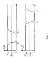
- den zeitlichen Verlauf der Ausgangssignale der beiden Feinstrahl-Lichtschranken,
- Fig. 5
- den detaillierten Aufbau eines Winnowings-Massenstrom-Sensors mit zwei Feinstrahl-Lichtschranken, und
- Fig. 6
- ein Diagramm Größe/Geschwindigkeit mit zwei Partikelklassen.
- Fig. 1
- a sample of Winnowings,
- Fig. 2a
- a sensor cross section with winnowings particles,
- Fig. 2b
- the detection range of a winnowing particle with a given orientation,
- Fig. 2c
- the response probability for a Winnowings particle with any orientation,
- Fig. 3
- the schematic structure of the mass flow measurement with two fine-beam photoelectric sensors in the Winnowing particle stream,
- Fig. 4
- the time course of the output signals of the two fine-beam photoelectric sensors,
- Fig. 5
- the detailed structure of a Winnowings mass flow sensor with two fine-beam photoelectric sensors, and
- Fig. 6
- a diagram of size / velocity with two particle classes.
Fig. 1 zeigt eine Probe von Winnowings, die direkt durch Aufstreuen auf die Abtastfläche eines Kopiergerätes abgebildet wurde. Die einzelnen Winnowings-Partikel sind zumeist langgestreckt mit Quermessungen hauptsächlich im Bereich von 0,5 bis 2 mm und Längenabmessungen im Bereich von 5 mm bis 20 mm.Fig. 1 shows a sample of winnowings directly by scattering onto the scanning surface a copier was mapped. The individual Winnowings particles are mostly elongated with transverse measurements mainly in the range of 0.5 to 2 mm and Length dimensions in the range of 5 mm to 20 mm.
Für die folgenden Abschätzungen wird daher mit einer über Längs- und Querdimension gemittelten Winnowings-Partikelabmessung von a = 2 mm gerechnet werden. Diese vereinfachende Vorgehensweise wird später noch eingehend diskutiert.For the following estimates is therefore with a longitudinal and transverse dimension averaged winnowing particle size of a = 2 mm. These simplifying procedure will be discussed in detail later.
Wie oben bereits erwähnt wurde, erfolgt bei der Cigarettenherstellung in der Cigarettenmaschine eine Sichtung des ankommenden Tabakstroms. Nur hinreichend feines Tabakmaterial wird in den Tabakstrang eingebaut, während der verbleibende Anteil an gröberem Material die Winnowings darstellt und an einem Ausgang der Cigarettenmaschine abgegeben und per Luftförderung für die weitere Verarbeitung zentral gesammelt wird.As mentioned above, takes place in the Cigarettenherstellung in the Cigarettenmaschine a sighting of the incoming tobacco stream. Only sufficiently fine Tobacco material is incorporated into the tobacco rod, while the remaining portion of coarser material represents the Winnowings and at an exit of the Cigarette machine delivered and centralized by air conveying for further processing is collected.
Auf diesem Weg werden die Winnowings durch das in Figur 2a dargestellte Förderrohr transportiert, das gleichzeitig auch als Sensor-Rohr dient. An diesem Sensor-Rohr ist eine Feinstrahl-Lichtschranke angeordnet, die auf einer Seite des Sensor-Rohrs eine Lichtquelle und auf der gegenüberliegenden Seite des Sensors-Rohrs einen Detektor aufweist. Der Messstrahl verläuft zentrisch durch den Rohrquerschnitt. Die Richtung des Messtrahles wird im folgenden als y-Richtung eines kartesischen Koordinatensystems benutzt. In this way, the winnowings through the conveyor pipe shown in Figure 2a transported, which also serves as a sensor tube. On this sensor tube is a Fine-beam photoelectric sensor arranged on one side of the sensor tube a light source and on the opposite side of the sensor tube comprises a detector. Of the Measuring beam runs centrically through the pipe cross-section. The direction of the measuring beam is used in the following as the y-direction of a Cartesian coordinate system.
Der Radius R des Rohres ist im Vergleich mit den Abmessungen der Winnowings-Partikel sehr groß.The radius R of the tube is compared with the dimensions of the winnowing particles very large.
Die Achse des Sensor-Rohrs wird als die z-Achse des Koordinatensystems benutzt. Die x-Achse des Koordinatensystems hat dann die in Fig. 2a angegebene Richtung.The axis of the sensor tube is used as the z-axis of the coordinate system. The x-axis of the coordinate system then has the direction indicated in Fig. 2a.
Die Winnowings-Partikel unterscheiden sich in ihren Flugbahnen (Schwerpunkts-Koordinaten {xi, yi} im Sensor) sowie in ihren Formen, Größen und Winkelorientierungen. Bei ungestörten Strömungsverhältnissen darf angenommen werden, dass die Flugbahnen der Winnowings-Partikel im statistischen Mittel gleichmäßig über den Rohrquerschnitt verteilt sind.The Winnowings particles differ in their trajectories (center of gravity coordinates {x i , y i } in the sensor) and in their shapes, sizes and angular orientations. In the case of undisturbed flow conditions, it may be assumed that the trajectories of the Winnowings particles are evenly distributed over the pipe cross section on a statistical average.
Die Querabmessungen des Lichtstrahls werden so klein gewählt, wie es technisch möglich ist. Sie dürften dann als vernachlässigbar klein vorausgesetzt werden im Vergleich zu allen Abmessungen der Winnowings-Partikel, so dass hier der Begriff "Feinstrahl-Lichtschranke" verwendet werden kann.The transverse dimensions of the light beam are chosen as small as technically possible is. They should then be assumed to be negligibly small compared to all Dimensions of Winnowings particles, so here the term "fine-beam photoelectric sensor" can be used.
In der Praxis hat der Messlichtstrahl beispielsweise einen Durchmesser DS von 0,1 mm. Die zugehörigen Detektoren werden so ausgelegt, dass sie hinreichend schnell ansprechen (beispielsweise im Bereich von 100 ns), um die Abmessungen der Partikel bei der Partikelgeschwindigkeit (typisch 25 m/s) genau zu bestimmen.In practice, the measuring light beam has, for example, a diameter D S of 0.1 mm. The associated detectors are designed to respond sufficiently quickly (for example, in the range of 100 ns) to accurately determine the dimensions of the particles at the particle velocity (typically 25 m / s).
Bei der Erfassung der Winnowings-Partikel mittels der Feinstrahl-Lichtschranke fliegt die Mehrzahl der geforderten Winnowings-Partikel an der Lichtschranke vorbei, und nur ein kleiner Teil wird tatsächlich erfasst. Da die Abmessungen der Winnowings-Partikel sehr viel größer sind als der Strahldurchmesser DS, erhält man bei bekannter Fördergeschwindigkeit v von jedem Partikel, das die Feinstrahl-Lichtschranke passiert, eine kurzzeitige Unterbrechung des Lichtstrahles. Bei gegebener Geschwindigkeit der Partikel ist die Dauer τi der Unterbrechung proportional zu dem auf die Flugbahn "projizierten" Durchmesser si des Partikels. Diese Pulsdauer wird, zusammen mit der gemessenen Geschwindigkeit vi des Partikels, benutzt, um seinen Durchmesser si zu berechnen und daraus dann sein Volumen und seine Masse. Aus den Massen mi, die für eine hinreichende Anzahl von Partikeln während einer Messzeit To erfasst wurden, folgt schließlich der gesamte Massenstrom.When the winnowing particles are detected by means of the fine-beam photoelectric barrier, the majority of the required winnowing particles fly past the photoelectric barrier, and only a small part is actually detected. Since the dimensions of the Winnowings particles are much larger than the beam diameter D S , one obtains a short-term interruption of the light beam at a known conveying speed v of each particle that passes through the fine-beam light barrier. For a given velocity of the particles, the duration τ i of the interruption is proportional to the to the flight path "projected" diameter s i of the particle. This pulse duration, together with the measured velocity v i of the particle, is used to calculate its diameter s i and then its volume and mass. From the masses mi, which were recorded for a sufficient number of particles during a measurement time T o , finally follows the entire mass flow.
Weil die Chance eines Partikels, von der Feinstrahl-Lichtschranke erfasst zu werden, mit seiner Größe zunimmt, muss bei dieser Berechnung des Massenstromes aus den Lichtschrankensignalen die Detektionswahrscheinlichkeit der Winnowings-Partikel mit berücksichtigt werden. Dies wird im folgenden anhand von Fig. 2b und 2c erläutert.Because the chance of a particle, to be detected by the fine-beam sensor, with increases in size, must in this calculation of the mass flow of the Light barrier signals with the detection probability of Winnowings particles with be taken into account. This will be explained below with reference to FIGS. 2b and 2c.
Die Abbildung 2b zeigt ein Winnowings-Partikel, das sich entlang der z-Richtung durch den Sensor bewegt und die Feinstrahl-Lichtschranke auslöst. Die Zeitdauer der erzeugten Unterbrechung hängt von der x-Position der Flugbahn ab, also τi = τ(x), außerdem von der Winkel-Orientierung des Winnowings-Partikels.Figure 2b shows a Winnowings particle moving through the sensor along the z-direction and triggering the fine-beam photoelectric sensor. The duration of the interruption generated depends on the x-position of the trajectory, ie τ i = τ (x), and also on the angle orientation of the winnowing particle.
Der in Fig. 2b gezeigte Verlauf der Funktion τ(x) gilt nur für die gezeigte Orientierung. Die Breite a1 des Bereiches, in dem τ ≠ 0 ist, ist der Detektionsbereich des Winnowings-Partikels bei der angegebenen Orientierung.The course of the function τ (x) shown in FIG. 2b applies only to the orientation shown. The width a 1 of the range in which τ ≠ 0 is the detection range of the winnowing particle at the given orientation.
Wird nun dasselbe Winnowings-Partikel in beliebiger Orientierung betrachtet, so tritt an die Stelle des Detektionsbereichs eine ortsabhängige Ansprechwahrscheinlichkeit wA(x) der Lichtschranke, die in Fig. 2c dargestellt ist. Sie wird durch Mittelung über alle Orientierungen erhalten.If the same Winnowings particle is now viewed in any desired orientation, a location-dependent response probability w A (x) of the light barrier, which is shown in FIG. 2c, takes the place of the detection area. It is obtained by averaging over all orientations.
Für sehr kleine Werte von |x|, also wenn die Flugbahn sehr nahe an der y-Achse und damit
sehr nahe an dem Lichtstrahl vorbeiführt, spricht die Schranke mit Sicherheit an, dort ist
Bei größeren Abständen |x| geht die Ansprechwahrscheinlichkeit kontinuierlich gegen 0.
Es wird deshalb eine mittlere Ansprechbreite am definiert entsprechend der Gleichung
In der Darstellung gemäß Fig. 2c bedeutet dies die Breite eines Rechtecks, das flächengleich mit der Fläche unter der Kurve wA(x) ist. Der genaue Wert dieser Breite hängt von der Form und der Größe des Partikels ab, nicht jedoch von seiner Winkelorientierung, denn hierüber ist gemittelt worden.In the illustration according to FIG. 2c, this means the width of a rectangle which is coextensive with the area under the curve w A (x). The exact value of this width depends on the shape and size of the particle, but not on its angular orientation, for this has been averaged.
Diese Größe am erlaubt es, die Wahrscheinlichkeit anzugeben, mit der das Winnowings-Partikel
von der Lichtschranke gezählt wird, wenn seine Bahn an einer beliebigen Stelle
durch den Querschnitt des Sensorrohrs verläuft. Diese Zählwahrscheinlichkeit wz beträgt
Dabei ist APi die Fläche des Streifens der Breite am und der Länge 2R, in dem das Winnowings-Partikel erfasst wird, während AQ = πR2 den Rohrquerschnitt angibt.Here, A Pi is the area of the strip of width a m and length 2R, in which the winnowings particle is detected, while A Q = πR 2 indicates the pipe cross-section.
Für ein einzelnes Partikel ist die Ansprechbreite am proportional zur Partikelgröße. Wird
nun vorausgesetzt, dass das Formenspektrum der Partikel stets gleich bleibt, so gilt
dieselbe Proportionalität auch für die Mittelwerte, und es kann eine mittlere
Ansprechbreite am angesetzt werden gemäß der Gleichung
Mittels dieser Beziehung kann aus der gemessenen Zählrate Z das Produkt Nα bestimmt
und zur Berechnung des Massenstroms µ verwendet werden. Dieser ergibt sich als
Zur weiteren Auswertung dieses Ausdruckes muss noch die Größe α2 gefunden werden. Sie folgt aus der mittleren Dauer der Lichtschrankensignale, wie im folgenden gezeigt wird.For further evaluation of this expression, the size α 2 must still be found. It follows from the average duration of the light barrier signals, as shown below.
Es war bereits erläutert worden, dass die Zeitdauer τi eines einzelnen Lichtschrankensignales abhängt von der genauen Durchstoßposition xi der Bahn des detektierten Partikels durch die Sensor-Ebene sowie von der Größe und Winkelorientierung des Partikels.It has already been explained that the time duration τ i of a single light barrier signal depends on the exact puncture position x i of the path of the detected particle through the sensor plane and on the size and angular orientation of the particle.
Da der Lichtschrankenstrahl vernachlässigbar dünn ist im Vergleich zu den Winnowings-Partikelabmessungen,
und da das Formenspektrum als konstant vorausgesetzt war, mitteln
sich die Abhängigkeiten der Pulsdauer τi von der Position xi und von der
Winkelorientierung für alle Partikel in gleicher Weise heraus, und es bleibt für alle Partikel
dieselbe Proportionalität der Pulsdauer zur Größe der Partikel. Folglich muss auch die
mittlere Pulsdauer τ proportional sein zur mittleren Partikelgröße α und umgekehrt
proportional zur Bewegungsgeschwindigkeit v der Partikel.
Hier sind alle Formfaktoren und andere Konstanten des Sensors in einem einzigen Faktor Γ1 zusammengefasst worden. Wegen der zahlreichen Annahmen, die in diesen Formfaktoren stecken, erscheint eine Berechnung dieses Faktors Γ1 jedoch nicht zweckmäßig. Statt dessen wird Γ1 durch eine Kalibrierung des Sensors ermittelt.Here all form factors and other constants of the sensor have been summarized in a single factor Γ 1 . However, because of the many assumptions inherent in these form factors, it does not seem appropriate to calculate this factor Γ 1 . Instead, Γ 1 is determined by calibrating the sensor.
Die Bestimmung der mittleren Pulsdauer τ kann technisch einfach dadurch erfolgen, dass die zeitlichen Dauern τi aller Pulse während einer Messzeit TO addiert werden und die Summe anschließend auf TO bezogen wird. Dazu genügt es im einfachsten Fall, die Pulse einer schnellen Quarzuhr jeweils während der Unterbrechungszeit τi der Lichtschranke auf einen summierenden Zähler zu leiten.The determination of the average pulse duration τ can be technically simple in that the time durations τ i of all pulses are added during a measurement time T O and the sum is then related to T O. For this purpose, it is sufficient in the simplest case to pass the pulses of a fast quartz clock in each case during the interruption time τ i of the light barrier to a summing counter.
Um Information über die Partikelgrößenverteilung zu erhalten, ist es notwendig, die Zeitdauer τi jedes Pulses einzeln abzuspeichern. Wenn dann nach Ablauf der Messzeit TO diese Werte für 103 ... 104 Partikel bekannt sind, kann der Rechner die gemessene Verteilung von τi-Werten graphisch auf dem Monitor darstellen. Zusätzlich kann der Rechner den Mittelwert τ und die Streubreite Δτ der Verteilung anzeigen oder per Datenbus einer übergeordneten Prozesssteuerung mitteilen.In order to obtain information about the particle size distribution, it is necessary to store the duration τ i of each pulse individually. If these values for 10 3 ... 10 4 particles are known at the end of the measurement time T O , the computer can graphically display the measured distribution of τ i values on the monitor. In addition, the computer can display the mean value τ and the spread Δτ of the distribution or communicate via data bus to a higher-level process control.
Alternativ zu der beschriebenen Auswertung bietet sich übrigens eine andere
Auswertemethode für den Massenstrom µ an. Dieser kann auch berechnet werden aus den
Massen mi bzw. Volumina Vi aller Partikel, die während einer gewissen Meßzeit TO
durch den gesamten Sensorquerschnitt fliegen:
Wie oben ausgeführt, ist die Detektionswahrscheinlichkeit proportional zur Größe des
Partikels. Es ist deshalb sinnvoll, die Gewichtung umgekehrt proportional zur Größe
vorzunehmen, also
Dies führt nach einigen Zwischenschritten auf die folgende alternative Auswertungsformel
Obwohl die Gleichung für µ1 mit dem einfachen und die Gleichung für µ2 mit dem quadratischen Mittelwert arbeitet, besteht zwischen beiden Gleichungen kein Widerspruch. Da nämlich ein festes, konstantes Formenspektrum vorausgesetzt worden war, muss auch ein fester Zusammenhang zwischen den beiden genannten Mittelwerten bestehen. Dieser muss sich in entsprechend unterschiedlichen Kalibrierfaktoren Γ1/Γ2 auswirken. Bei Gültigkeit der genannten Voraussetzung bleibt es dann gleich, welche der beiden Gleichungen man zur Berechnung des Massenstromes verwendet.Although the equation for μ 1 works with the simple and the equation for μ 2 with the root-mean-square value, there is no contradiction between the two equations. Since a firm, constant spectrum of forms had been assumed, there must also be a firm connection between the two averages. This must have an effect in accordance with different calibration factors Γ 1 / Γ 2 . If the above assumption is valid, then it remains the same which of the two equations is used to calculate the mass flow.
In der Praxis wird die Voraussetzung des festen Formenspektrums allerdings nicht perfekt erfüllt sein. Dann bietet der Vergleich der beiden nach obigen Gleichungen ermittelten Massenstrom-Werte die Möglichkeit, auftretende Abweichungen online festzustellen. Wird zu einem Zeitpunkt plötzlich ein Unterschied zwischen den berechneten Massenstromwerten µ1 und µ2 beobachtet, so kann evtl. eine Auswertung der Pulsdauer-Statistik τi Auskunft darüber geben, wo die Ursache der Abweichung zu suchen ist, und welcher der beiden Massenstromwerte dann eine höhere Signifikanz besitzt.In practice, however, the prerequisite of the fixed spectrum of forms will not be perfectly fulfilled. Then the comparison of the two mass flow values determined according to the above equations offers the possibility of ascertaining occurring deviations online. If suddenly a difference between the calculated mass flow values μ 1 and μ 2 is observed at one time, an evaluation of the pulse duration statistics τ i can possibly provide information about where the cause of the deviation is to be found and which of the two mass flow values then a has higher significance.
Aus den obigen Überlegungen ergibt sich also, dass sich aus den Pulsdauern der Messsignale der Feinstrahl-Lichtschranke bzw. aus der mittleren Pulsdauer τ die mittleren Winnowings-Partikel-Abmessung α und andere wesentliche Parameter der Winnowings-Partikel-Verteilung ermitteln lassen.From the above considerations, it follows that the pulse durations of the Measuring signals of the fine-beam sensor or from the average pulse duration τ the middle Winnowings particle dimension α and other key parameters of Winnowings particle distribution can be determined.
Für die obigen Berechnungen war die Kenntnis der Bewegungsgeschwindigkeit v der Winnowings-Partikel erforderlich. Zu ihrer Messung stehen verschiedene Methoden zur Verfügung. Im einfachsten Fall dürfte die Geschwindigkeit der Förderluft im Sensorrohr ausreichen.For the above calculations, the knowledge of the motion velocity v was the Winnowings particles required. For their measurement, various methods are available Available. In the simplest case, the speed of the conveying air in the sensor tube is likely suffice.
Nach einer bevorzugten Ausführungsform wird jedoch der Winnowings-Produktstrom mit Hilfe von zwei Feinstrahl-Lichtschranken abgetastet, die in einem kurzen Abstand b12 hintereinander in dem Sensorrohr angebracht sind, siehe Fig. 3. Indem die Zeitdifferenz t12 = v · b12 der Signale der 1. und der 2. Feinstrahl-Lichtschranke ausgewertet wird, ist es somit möglich, die Partikelgeschwindigkeit v direkt im Sensor selbst zu bestimmen. Damit wird der Partikelsensor autark, unabhängig von anderen Messgeräten.According to a preferred embodiment, however, the Winnowings product stream is scanned with the aid of two fine-beam photoelectric sensors, which are mounted in a short distance b 12 in succession in the sensor tube, see Fig. 3. By the time difference t 12 = v · b12 of the signals 1. and the second fine beam photoelectric sensor is evaluated, it is thus possible to determine the particle velocity v directly in the sensor itself. This makes the particle sensor self-sufficient, independent of other measuring devices.
Ein solches Messverfahren mit zwei Feinstrahl-Lichtschranken kann neben dem Massenstrom µ, die Partikelgröße, die Größenvariation und die Fördergeschwindigkeit der Winnowings-Partikel liefern, wie man Fig. 3 entnehmen kann. Such a measuring method with two fine-beam photoelectric sensors, in addition to the Mass flow μ, the particle size, the size variation and the conveying speed of the Winnowings particles provide, as can be seen in FIG.
Die beiden Feinstrahl-Lichtschranken weisen jeweils Lichtquellen L1 und L2 sowie Detektoren D1 und D2 auf, die in dem Sensor-Rohr oder außerhalb desselben angeordnet sind. Bei einer Anordnung außerhalb des Sensor-Rohres müssen hinter den Lichtquellen bzw. vor den Detektoren transparente Fenster in die Wandung des Sensor-Rohrs eingebaut werden, um den Durchgang der Feinlichtstrahlen zu ermöglichen.The two fine-beam light barriers each have light sources L 1 and L 2 and detectors D 1 and D 2 , which are arranged in the sensor tube or outside thereof. In an arrangement outside the sensor tube transparent windows must be installed in the wall of the sensor tube behind the light sources or in front of the detectors to allow the passage of the fine light beams.
Zur Bestimmung des Massenstroms µ werden die Lichtschranken-Signale aller Winnowings-Partikel ausgewertet, die während einer voreingestellten Messzeit T0 beobachtet werden. In der Praxis liegt ein typischer Wert dieser Messzeit bei T0 = 100 s. Die in dieser Zeit T0 von den Feinstrahl-Lichtschranken erfasste Teilchenzahl zwischen 1.000 und 10.000 Teilchen ist hinreichend groß, um daraus auf die Anzahl der insgesamt durch den Gesamtquerschnitt des Sensors geförderten Winnowings-Partikel mit einem Fehler in der Größenordnung von 3 % oder weniger schließen zu können. Durch Wahl einer längeren Messzeit oder Verwendung mehrerer Feinstrahl-Lichtschranken parallel nebeneinander ließe sich diese Genauigkeit noch weiter verbessern.To determine the mass flow μ, the light barrier signals of all winnowing particles are evaluated, which are observed during a preset measurement time T 0 . In practice, a typical value of this measuring time is T 0 = 100 s. The particle number between 1,000 and 10,000 particles detected by the fine-beam photoelectric sensors in this time T 0 is sufficiently large to conclude from this that the total number of winnowing particles conveyed through the overall cross section of the sensor has an error of the order of 3% or less to be able to. By choosing a longer measurement time or using multiple fine-beam photoelectric sensors in parallel to each other, this accuracy could be further improved.
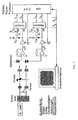
Die Detektor-Elektronik ist schematisch in Fig. 5 dargestellt.The detector electronics are shown schematically in FIG.
Das Konzept des Sensors sieht vor, dass der Lichtstrahl von den Partikeln vollständig unterbrochen wird. Infolge von Streulicht und Fremdlicht kann allerdings auch in den Dunkelzeiten noch ein kleines Signal vorhanden sein. Bei zweckmäßigem Aufbau der Lichtschranke (langer dünner schwarzer Tubus vor dem Detektor) kann dieses Restsignal so klein gemacht werden, dass ein Ein/Aus-Kontrast von mindestens 100 : 1 erreicht wird. Es ergibt sich somit der in Figur 4 skizzierte Signalverlauf.The concept of the sensor provides that the light beam from the particles completely is interrupted. As a result of stray light and extraneous light, however, in the Dark times still a small signal to be present. With appropriate structure of Photocell (long thin black tube in front of the detector) can this residual signal be made so small that an on / off contrast of at least 100: 1 is achieved. This results in the waveform sketched in FIG.
Die vom Detektor kommenden Pulse sind "Dunkelpulse". Die aus ihnen auszuwertende Information sind die in Figur 4 markierten Zeitpunkte t1 und t2 für die (in Flugrichtung gesehen) erste Lichtschranke, sowie t3 und t4 für die zweite Lichtschranke. Zu diesen Zeitpunkten geht die Spannung U1(t) bzw. U2(t) durch den 50% Pegel ihres 'normalen' Wertes UD, der während der relativ langen Pausen zwischen den Pulsen besteht. Bei der praktischen Auslegung der Schaltung ist zu beachten, dass die 'normalen' Spannungen UD1 und UD2 an den beiden Lichtschranken im allgemeinen etwas verschiedene Höhen haben.The pulses coming from the detector are "dark pulses". The evaluated information from them are marked in Figure 4 time points t 1 and t 2 for the (in the direction of flight seen) first light barrier, and t 3 and t 4 for the second light barrier. At these times, the voltage U 1 (t) or U 2 (t) passes through the 50% level of their 'normal' value U D , which exists during the relatively long pauses between the pulses. In the practical design of the circuit is to be noted that the 'normal' voltages U D1 and U D2 on the two light barriers generally somewhat at different heights.
Es ist deshalb zweckmäßig, die Spannungspegel UD1 und UD2 aus den betreffenden Detektorsignalen durch 'Spitzenwert-Gleichrichtung' zu gewinnen, welche die kurzzeitigen 'Einbrüche' (Dunkelpulse) der Spannungen U1(t) und U2(t) überbrückt, sich aber mit einer Zeitkonstante von z.B. 1 s an langsame Änderungen der Laserleistung anpasst.It is therefore expedient to obtain the voltage levels U D1 and U D2 from the relevant detector signals by 'peak rectification', which bridges the short-term 'dips' (dark pulses) of the voltages U 1 (t) and U 2 (t) but with a time constant of eg 1 s to slow changes in laser power adapts.
Aus UD1 und UD2 werden in zwei Spannungsteilern die Spannungen 1/2 UD1 und 1/2 UD2 gewonnen, die als Referenz für zwei Trigger-ICs dienen. Diese werden so ausgelegt, dass sie normierte Ausgangssignale TR1 .... TR4 abgeben, wenn ihre Eingangsspannungen u1(t) und u2(t) von oben nach unten (TR 1 und TR3) bzw. von unten nach oben (TR2 und TR4) durch die jeweilige Referenzspannung gehen.From U D1 and U D2 , the voltages 1/2 U D1 and 1/2 U D2 are obtained in two voltage dividers, which serve as a reference for two trigger ICs. These are designed such that they emit TR1 .... TR4 normalized output signals when their input voltages u 1 (t) and u 2 (t) from top to bottom (TR 1 and TR 3) or from the bottom up (TR2, and TR4) through the respective reference voltage.
Die Triggersignale werden digitalen Eingängen eines digitalen Signalprozessors (DSP)
zugeführt und veranlassen jeweils, dass die zentrale Uhr (z.B. 10 MHz-Takt) des DSP
abgelesen und die momentane Zeit ti gespeichert wird. Wenn die letzte Ablesung (t4)
erfolgt ist, wird der Datensatz [t1, t2, t3, t4] sofort im DSP ausgewertet, um die mittlere
Pulsdauer τP und die Flugzeit τF zu bestimmen:
Die Divisionen durch 2 brauchen nicht im DSP ausgeführt zu werden, sie können später bei der Auswertung im PC erfolgen. Sie sind hier dennoch angegeben, um mit verständlicheren Größen zu arbeiten. Die Berechnung von τP und τF erfordert im DSP somit nur Additionen und Subtraktionen ganzer Zahlen und kann sehr schnell, also online, durchgeführt werden.The divisions by 2 need not be executed in the DSP, they can be done later in the evaluation in the PC. They are nevertheless given here to work with more understandable sizes. The computation of τ P and τ F thus requires only additions and subtractions of integers in the DSP and can be performed very fast, ie online.
Das Datenpaar {τP,τF} könnte dann sofort vom Prozessor an den PC übertragen werden. Es ist jedoch effizienter, eine gewisse Anzahl solcher Datenpaare zu sammeln, bevor sie übertragen werden, beispielsweise 1x pro Sekunde oder jeweils dann, wenn der DSP-interne Speicher gefüllt ist. Die Rate, mit der diese Datenpaare anfallen, hängt von dem zu messenden Massenstrom ab; sie sollte praktisch nicht größer sein als 3.000 Datenpaare/Sekunde, könnte in Grenzfällen aber Werte bis zu 10.000 Paare/Sekunde erreichen.The data pair {τ P , τ F } could then be transferred immediately from the processor to the PC. However, it is more efficient to collect a certain number of such data pairs before they are transmitted, for example, once per second, or whenever the DSP internal memory is full. The rate at which these data pairs are generated depends on the mass flow to be measured; it should be practically no larger than 3,000 data pairs / second, but could reach values of up to 10,000 pairs / second in borderline cases.
Es ist nicht zwingend notwendig, jedes Partikel, das die Trigger auslöst, mit seinen Daten {τP,τF} zu erfassen und der Auswertung im PC zuzuführen. Es ist zulässig, während der Datenübertragung zum PC den Signalprozessor für die Registrierung weiterer Partikel zu sperren, und ihn erst nach der Übertragung wieder freizugeben. Dies gilt uneingeschränkt, wenn diese Unterbrechungszeiten nur einen kleinen Bruchteil (weniger als 1 %) der Gesamtzeit ausmachen. Da die jeweils statistisch ausgewerteten Partikelzahlen groß sind, wird die erreichte Messgenauigkeit durch solche gelegentlichen kurzen Unterbrechungen nicht wesentlich herabgesetzt. Wenn die 'Totzeit' des Sensors infolge der Übertragungen aber einen größeren Wert als etwa 1 % der gesamten Messzeit erreicht, so wird es notwendig, die Länge dieser Totzeiten zu protokollieren und sie bei der letztendlichen Berechnung des Massenstromes als Korrektur zu berücksichtigen.It is not absolutely necessary to record each particle that triggers the trigger with its data {τ P , τF} and to feed it to the PC for evaluation. It is permissible to block the signal processor during the data transmission to the PC for the registration of further particles, and to release it only after the transmission. This is fully applicable if these interruption times represent only a small fraction (less than 1%) of the total time. Since the respectively statistically evaluated particle numbers are large, the achieved measuring accuracy is not significantly reduced by such occasional short interruptions. However, if the 'dead time' of the sensor due to the transmissions reaches a value greater than about 1% of the total measurement time, it becomes necessary to log the length of these dead times and consider them as a correction in the final mass flow calculation.
Bei derartigen Operationen, aber auch im normalen Betrieb, kann es vorkommen, dass von einem Partikel nicht der vollständige Satz von vier Zeitablesungen [t1, t2, t3, t4] erfasst wird. Ferner kann es vorkommen, dass sich zwei Partikel gleichzeitig im Bereich der Lichtschranken befinden, und dass sich ihre Triggersignale zeitlich 'vermischen'. Dies muss vom Prozessor fortlaufend überprüft werden, und unvollständige Datensätze [t1, t2, t3, t4] dürfen nicht weiterverarbeitet werden. Zu diesem Zweck wird für jedes Partikel ein 'Partikel-Zeitfenster' definiert. Es beginnt, sobald ein Triggersignal TR1 auftritt, und läuft dann über eine fest vorgegebene (programmierbare) Zeitdauer TP. Diese Zeit wird etwas länger gewählt als die längste vorkommende Zeit (t4 - t1), die von dem größten möglichen Partikel bei langsamster Fördergeschwindigkeit zum Durchlaufen des Sensors benötigt wird. Die Dauer dieses 'Partikel-Zeitfensters' liegt typisch bei TP = 150 - 500 µs. Während dieser Zeit dürfen vom Prozessor keine weiteren Triggersignale TR1 angenommen werden. Um die Vollständigkeit der vier benötigten Zeitablesungen zu überprüfen, könnten zu Beginn eines jeden Zeitfensters die drei Speicher für t2, t3, t4 auf Null gesetzt werden. Beim Eintreffen der Triggerpulse TR2, TR3 und TR4 werden diese Nullen dann mit den abgelesenen Zeiten t2, t3 bzw. t4 überschrieben. Dabei muss sichergestellt sein, dass in jeden der drei Speicher nur einmal geschrieben werden kann, um Konfusionen zu vermeiden, die evtl. durch ein nachfolgendes zweites Partikel auftreten könnten. Nach Ablauf des Zeitfensters TP wird geprüft, ob die drei Speicher für t2, t3, t4 tatsächlich ungleich 0 sind. Falls ja, werden die Daten weiterverarbeitet; falls nein, wird der Datensatz verworfen, und gleichzeitig wird ein Zähler zur Registrierung dieser Vorgänge um eins erhöht. Erst nach Ablauf von TP werden alle Speicher wieder freigegeben, und beim Auftreten eines neuen Pulses TR1 kann ein neues Zeitfenster beginnen.In such operations, but also in normal operation, it may happen that a particle does not detect the complete set of four time readings [t 1 , t 2 , t 3 , t 4 ]. Furthermore, it can happen that two particles are located at the same time in the area of the light barriers and that their trigger signals 'mix' in time. This must be checked continuously by the processor, and incomplete data sets [t 1 , t 2 , t 3 , t 4 ] must not be further processed. For this purpose a 'particle time window' is defined for each particle. It begins as soon as a trigger signal TR1 occurs, and then runs for a fixed (programmable) period of time T P. This time is chosen to be slightly longer than the longest occurring time (t 4 -t 1 ) required by the largest possible particle at the slowest rate to travel through the sensor. The duration of this 'particle time window' is typically T P = 150-500 μs. During this time, no further trigger signals TR1 may be accepted by the processor. In order to check the completeness of the four required time readings, the three memories for t 2 , t 3 , t 4 could be set to zero at the beginning of each time window. When the trigger pulses TR2, TR3 and TR4 arrive, these zeros are then overwritten with the read times t 2 , t 3 and t 4 , respectively. It must be ensured that in each of the three memories can be written only once to avoid confusion, which could possibly occur through a subsequent second particle. After the time window T P has elapsed, it is checked whether the three memories for t 2 , t 3 , t 4 are actually not equal to 0. If so, the data is processed further; if not, the record is discarded and, at the same time, a counter for registering these operations is incremented by one. Only after the expiration of T P all memories are released again, and when a new pulse TR1 occurs, a new time window can begin.
Es ist eine Konsequenz der Einführung dieses 'Partikel-Zeitfensters', dass das System
während der Zeit TP 'tot' ist und kein neues Partikel registrieren kann, das evtl. kurz nach
dem ersten eintrifft. Dadurch entgeht ein gewisser Bruchteil der Partikel der Messung. Eine
Analyse dieser Situation zeigt, dass die Wahrscheinlichkeitsverteilung der zeitlichen
Abstände aufeinanderfolgender Partikel durch eine Exponentialfunktion gegeben ist:
Hierbei bedeutet Tm die mittlere Zeit zwischen zwei Partikeln. Der Verlust der Signale von
Partikeln, die während der Totzeit eintreffen, reduziert die Nachweiswahrscheinlichkeit des
Systems von 100 % auf den Wert
Da das System die mittlere Zeit Tm zwischen den Partikeln kennt, kann es diese reduzierte Nachweiswahrscheinlichkeit berechnen und sie bei der Ermittlung des Massenstromes als Korrekturfaktor berücksichtigen. Praktisch ist das Gesamtsystem aber so ausgelegt, dass diese Korrektur im allgemeinen klein (< 10 %) bleibt.Since the system knows the mean time T m between the particles, it can calculate this reduced detection probability and take it into account as a correction factor when determining the mass flow. In practice, however, the overall system is designed so that this correction generally remains small (<10%).
Dennoch ist es sinnvoll anzustreben, dass die Berechnung von τP und τF, wenn möglich, außerhalb des Zeitfensters erfolgt, um möglichst wenig Messzeit zu verlieren. Dies ist praktisch realisierbar, weil der DSP während des Zeitfensters relativ wenig zu tun hat (nur die Abspeicherung der drei Zeiten), so dass die Berechnung von τp und τF eines Datensatzes jeweils zu Beginn des folgenden Datensatzes durchgeführt werden kann.Nevertheless, it makes sense to strive for the calculation of τ P and τ F , if possible, to take place outside the time window in order to lose as little measuring time as possible. This is practically feasible, because the DSP has relatively little to do during the time window (only the storage of the three times), so that the calculation of τ p and τ F of a data set can be performed at the beginning of each successive data set.
Aus dem gleichen Grund ist es sinnvoll, die Länge des Zeitfensters 'dynamisch' festzulegen, angepasst an die vorliegende Fördergeschwindigkeit. Ein anderer Schritt in dieselbe Richtung ist es schließlich, auch das Zeitfenster aufzuspalten in zwei solche Fenster, jeweils eines für jede der beiden Lichtschranken, und diese Fenster um die Flugzeit τF zeitlich gegeneinander zu versetzen. Auf diese Weise kann die insgesamt auftretende Totzeit etwa halbiert werden im Vergleich mit der oben beschriebenen Situation mit einem einzigen, festen, alle vier Zeitpunkte t1 - t4 umfassenden Zeitfenster.For the same reason, it makes sense to set the length of the time window 'dynamically', adapted to the present conveying speed. Finally, it is another step in the same direction to split the time window into two such windows, one for each of the two light barriers, and to temporally offset these windows by the time of flight τ F. In this way, the total dead time can be approximately halved compared to the situation described above with a single, fixed, all four times t 1 - t 4 comprehensive time window.
Wenn ein Partikel den Strahl einer Lichtschranke nur 'streift', ist der erzeugte Dunkelpuls nicht voll ausgebildet, sondern nur partiell. Falls im Minimum des Pulses das Signal u1(t) ganz oberhalb der Triggerschwelle 1/2 UD1 bleibt, wird das betreffende Partikel einfach ignoriert. Entsprechendes gilt für die andere Lichtschranke. Ungünstiger ist der Fall, wo zwar die Triggerschwelle 1/2 UD1 unterschritten und ein Triggersignal TR1 ausgelöst wird, das Signal aber nur wenig unter die Schwelle reicht. Dann würde das betreffende Partikel mit einer zu kurzen Pulsdauer registriert werden, die nicht seiner wahren Größe entspricht.If a particle only 'touches' the beam of a light barrier, the generated dark pulse is not fully formed, but only partially. If, in the minimum of the pulse, the signal u 1 (t) remains completely above the trigger threshold 1/2 U D1 , the particle in question is simply ignored. The same applies to the other light barrier. Unfavorable is the case where, although the trigger threshold 1/2 U D1 falls below and a trigger signal TR1 is triggered, the signal but only slightly below the threshold. Then the particle in question would be registered with too short a pulse duration, which does not correspond to its true size.
Um die hierdurch bedingten Fehler zu reduzieren, können die Auswertung und Weitergabe des Datensatzes [t1, t2, t3, t4] davon abhängig gemacht werden, dass u1(t) eine zweite Triggerschwelle unterschreiten muss, die z.B. bei O,1 UD1 eingerichtet wird. Entsprechend müsste auch das Signal u2(t) der zweiten Lichtschranke auf totale Abdunklung überprüft werden. Praktisch wird dieser Fehler in Folge nur partieller Abdunklung bei der Massenstrom-Messung nicht bedeutsam sein, solange das Partikelgrößen-Spektrum konstant ist. Je nach Art dieses Spektrums wird nämlich stets ein bestimmter, fester Bruchteil der Partikel aufgrund dieser nur partiell ausgeprägten Lichtschranken-Signale der Erfassung entgehen. Wenn das System durch Vergleich mit einer genauen offline Methode (z.B. Wägung) kalibriert wird, so ist dieser Bruchteil bereits in der Kalibrierungskonstante berücksichtigt. Nur wenn sich das Spektrum und damit der erwähnte Bruchteil ändern, würde die Kalibrierung nicht mehr zutreffen und es entstünde ein Fehler in der Massenstrom-Anzeige. In order to reduce the errors caused thereby, the evaluation and forwarding of the data set [t 1 , t 2 , t 3 , t 4 ] can be made dependent on u 1 (t) having to fall below a second trigger threshold which, for example, at O, 1 U D1 is set up. Accordingly, the signal u 2 (t) of the second light barrier should also be checked for total darkening. In practice, this error will not be significant as a result of partial darkening in the mass flow measurement as long as the particle size spectrum is constant. Depending on the nature of this spectrum, a certain, fixed fraction of the particles will always escape detection because of these only partially marked light barrier signals. If the system is calibrated by comparison with an accurate offline method (eg, weighing), this fraction is already included in the calibration constant. Only if the spectrum and thus the mentioned fraction change, the calibration would no longer apply and there would be an error in the mass flow display.
Für die Gewinnung sauberer Triggersignale ist es zweckmäßig, die Verstärkung der Vorverstärker so zu regeln, daß die Spannungen UD einen näherungsweise konstanten Wert haben. Wenn im Laufe des Betriebes die Transmission der Fenster abnimmt, etwa weil sich Staub aus dem Produktstrom auf den Fenstern absetzt, wird diese Regelung immer weiter 'beansprucht'. Je geringer die Fenster-Transmission wird, desto höher wird die Verstärkung. Hier sollte eine Schwelle vorgesehen werden, die bei etwa 70% (-3 dB) vom Normalwert (saubere Fenster) liegt. Wird die Schwelle überschritten, gibt der DSP einen Alarm an den PC abgeben: "Fenster reinigen!" 'Auf diese Weise wird eine Selbstüberwachung des Transmissionszustandes der Fenster erreicht.For the recovery of clean trigger signals, it is expedient to regulate the gain of the preamplifier so that the voltages U D have an approximately constant value. If, in the course of operation, the transmission of the windows decreases, for example because dust settles on the windows from the product flow, this regulation is continually 'claimed'. The lower the window transmission, the higher the gain. Here, a threshold should be provided that is approximately 70% (-3 dB) from the normal value (clean windows). If the threshold is exceeded, the DSP issues an alarm to the PC: "Clean the window!"'In this way, a self-monitoring of the transmission state of the windows is achieved.
Das Funktionsprinzip des Sensors erfordert es, dass die Laserstrahlen der beiden Lichtschranken in der Flugrichtung möglichst dünn sind, damit die Partikelgröße mit guter Genauigkeit gemessen werden kann. Dies ist durch Verwendung eines sorgfältig fokussierten Gaußschen Strahles möglich.The operating principle of the sensor requires that the laser beams of the two Photocells in the direction of flight are as thin as possible, so that the particle size with good Accuracy can be measured. This is by using a carefully focused Gaussian beam possible.
In der dazu senkrechten Richtung, also quer zur Flugrichtung der Partikel, besteht zunächst keine derartige Einschränkung für die Breite 2wo,q der Laserstrahlen. Auch hier ist es aber angebracht, den Strahl möglichst 'dünn' zu machen: Ein breiterer Strahl hätte nämlich den Nachteil, dass Partikel, deren Durchmesser kleiner ist als die Breite des Strahles, diesen nicht mehr vollständig unterbrechen, sondern ihn nur partiell blockieren können. Sie würden dann aufgrund der im vorigen Abschnitt beschriebenen zweiten Triggerschwelle ganz aus der Messung herausfallen.In the direction perpendicular thereto, ie transversely to the direction of flight of the particles, there is initially no such restriction for the width 2w o, q of the laser beams. Again, it is appropriate to make the beam as possible 'thin': namely, a broader beam would have the disadvantage that particles whose diameter is smaller than the width of the beam, this no longer completely interrupt, but can only partially block it. You would then fall out of the measurement due to the second trigger threshold described in the previous section.
Von einem formal-mathematischen Standpunkt aus lassen sich die beiden oben beschriebenen
Verfahren zur Berechnung des Massenstromes µ aus den gemessenen
Unterbrechungszeiten τi der Lichtschranke auffassen als Sonderfälle einer allgemeineren
Reihe möglicher Berechnungsverfahren, bei denen die sogenannten 'Momente' der
gemessenen Unterbrechungszeiten τi gebildet und zur Berechnung des Massenstromes
verwendet werden. Für eine feste, vorgegebene Größenverteilung der Partikel kann nämlich
im Prinzip jeder der mit q = 0,1,2,3 ... gebildeten Zeitmittelwerte
Es ist ersichtlich, dass die nach den oben beschriebenen Verfahren resultierenden Ausdrücke µ1 und µ2 Spezialfälle (für q = 1 und q = 2) dieser allgemeineren Darstellung sind. Deshalb ist es praktisch von Interesse, für die Massenstrom-Auswertung mehrere Varianten des hier zuletzt formulierten Berechnungsverfahrens mit den drei Parameterwerten q = 1, 2, 3 zu verwenden.It can be seen that the expressions μ 1 and μ 2 resulting from the methods described above are special cases (for q = 1 and q = 2) of this more general representation. Therefore, it is of practical interest to use for the mass flow evaluation several variants of the calculation method last formulated here with the three parameter values q = 1, 2, 3.
Bei einer Änderung des Spektrums der Partikelgrößen ai werden sich dann die für verschiedene q berechneten Werte des Massenstromes µ unterscheiden. Es bleibt der praktischen und ausführlicheren Erprobung dieses Sensors vorbehalten, den optimalen Index q festzustellen.If the spectrum of the particle sizes a i is changed, the values of the mass flow μ calculated for different q will then differ. It remains the practical and more detailed testing of this sensor reserved to determine the optimal index q.
In der bisher gegebenen Beschreibung war vorausgesetzt worden, dass alle Partikel dieselbe Dichte p, dieselbe Geschwindigkeit v und dasselbe Formenspektrum haben. Lässt man diese Voraussetzungen fallen und bestimmt für jedes Partikel einzeln seine Geschwindigkeit vi, so lassen sich die Partikel nach ihren Dichten pi und ihren Formen unterscheiden. Mit einer solchen aufwendigeren Auswertungstechnik kann die erfindungsgemäße Feinstrahl-Lichtschranke auch benutzt werden, um den aus der Cigarettenmaschine kommenden Partikelstrom zu klassieren. In the description so far given it had been assumed that all particles have the same density p, the same velocity v and the same shape spectrum. If these assumptions are dropped and the velocity v i determined for each particle, the particles can be distinguished according to their densities p i and their shapes. With such a more elaborate evaluation technique, the fine beam photoelectric sensor according to the invention can also be used to classify the particle stream coming from the cigarette machine.
Der bei der Cigarettenherstellung anfallende Winnowings-Strom setzt sich in der Regel aus zwei Komponenten zusammen, nämlich Rippen-Partikel und Blatt- bzw. Lamina-Partikel. Diese beiden Komponenten unterscheiden sich sowohl in der Dichte als auch in der Form, wobei die Dichte der Lamina-Partikel etwas höher als die Dichte der Rippen ist und Lamina-Partikel komplexe Formen haben, während die Rippen-Partikel einfache, gerade Formen haben.The Winnowings current accumulating in cigarettes usually breaks down two components together, namely ribbed particles and leaf or lamina particles. These two components differ both in density and in shape, wherein the density of the lamina particles is slightly higher than the density of the ribs and Lamina particles have complex shapes, while the ribbed particles are simple, straight Have shapes.
Aufgrund dieser Unterschiede in den angesprochenen physikalischen Eigenschaften bewegen sich Rippen-Partikel einerseits und Lamina-Partikel andererseits auch mit unterschiedlicher Geschwindigkeit relativ zur Trägerströmung der pneumatischen Tabakförderung.Because of these differences in the physical properties mentioned On the other hand, ribbed particles and lamina particles move with them different speed relative to the carrier flow of the pneumatic Tobacco promotion.
Da durch die Feinstrahl-Lichtschranke mit zwei Lichtstrahlen sowohl die individuelle Partikelgröße als auch die Geschwindigkeit der Partikel bestimmt werden kann, lassen sich diese beiden Messwerte in dem Diagram nach Figur 6 aufzeichnen, bei dem die Größe der Partikel über ihrer Geschwindigkeit aufgetragen wird.Because of the fine-beam photoelectric sensor with two light beams both the individual Particle size as well as the speed of the particles can be determined can be record these two measurements in the diagram of Figure 6, in which the size of the Particles are applied above their speed.
Wie man erkennt, sind bei dieser Darstellung die Messwerte in zwei Bereichen konzentriert, die man zwei verschiedenen Partikel-Klassen zuordnen kann, nämlich den Rippen als Partikelklasse 1 einerseits und den Lamina-Partikeln als Partikelklasse 2 andererseits.As you can see, the measurements in this area are in two areas concentrated, which can be assigned to two different particle classes, namely the Ribs as particle class 1 on the one hand and the lamina particles as particle class 2 on the other hand.
Die im DSP abgelegten Messwerte werden auf Intervalle beschränkt, die den auftretenden Partikelklassen zugeordnet sind. Wählt man die Massenströme nur innerhalb der Intervalle der einzelnen Partikelklassen aus, so können die Massenströme auch für die einzelnen Partikelklassen, nämlich Lamina-Partikel und Rippen-Partikel, getrennt bestimmt werden.The measured values stored in the DSP are limited to intervals which correspond to the occurring values Particle classes are assigned. If one chooses the mass flows only within the intervals of the individual particle classes, so the mass flows can also for the individual Particle classes, namely lamina particles and rib particles, to be determined separately.
Die Lagen der einzelnen Partikelklassen in dem Größe/Geschwindigkeit-Diagramm können entweder durch Berechnung unter Benutzung der bekannten strömungsmechanischen Gleichungen oder durch eine messtechnische Kalibrierung ermittelt werden, indem Proben der einzelnen, vorkommenden Partikelklassen, insbesondere Lamina-Partikel und Rippen, durch die Messstrecke gefördert und vermessen werden. Die Bereiche, in denen sich für die einzelnen Partikelklassen die gehäuften Messwerte ergeben, werden dann den entsprechenden Partikelklassen zugeordnet.The locations of each particle class in the size / velocity graph can be either by calculation using the known fluid mechanics Equations or by a metrological calibration can be determined by specimens the individual, occurring particle classes, in particular lamina particles and ribs, be conveyed through the measuring section and measured. The areas in which are for the individual particle classes give the heaped measured values, then the assigned to corresponding particle classes.
Auf diese Weise kann die erfindungsgemäße Feinstrahl-Lichtschranke auch als "Rippen-Sensor" bzw. als "Lamina-Sensor" eingesetzt werden, so dass unter Verwendung einer geeigneten Rückkopplungsschleife in den Cigarettenherstellungsprozess eingegriffen werden kann, um beispielsweise den Anteil von Lamina-Teilchen in dem Winnowing-Massenstrom zu verringern.In this way, the fine-beam sensor according to the invention can also be used as a "rib sensor" or be used as a "lamina sensor", so that using a appropriate feedback loop in the cigarette manufacturing process intervened For example, the proportion of lamina particles in the winnowing mass flow can be to reduce.
Es hat sich als zweckmäßig herausgestellt, wenn der Darstellung in dem
Größe/Geschwindigkeits-Diagramm nicht die aktuellen Geschwindigkeiten, sondern die
Relativgeschwindigkeit in Bezug auf die Geschwindigkeit des Fördermediums für den
Tabakpartikel-Strom, also die sogenannte Schlupfgeschwindigkeit vS gemäß der Gleichung
Die Geschwindigkeit vf des fluiden Transportmediums wird entweder durch eine separate Messvorrichtung, beispielsweise durch ein Anemometer, oder anhand der auftretenden Maximal-Geschwindigkeiten v ermittelt, die den Geschwindigkeiten v der kleinsten, gerade noch nachweisbaren Tabakpartikel entsprechen, deren Schlupf sehr gering ist und die deshalb in guter Näherung ein Mass für die Geschwindigkeit vf des Fördermediums darstellen.The velocity v f of the fluid transport medium is determined either by a separate measuring device, for example by an anemometer, or by the occurring maximum velocities v, which correspond to the velocities v of the smallest, just yet detectable tobacco particles whose slippage is very low and which therefore to a good approximation represent a measure of the velocity v f of the pumped medium.
Claims (26)
- A method for detecting/measuring the particles of a tobacco particle stream in the production of smokable articles, comprising the following features:a) scanning the tobacco particle stream by means of a fine-beam light barrier having a beam diameter (DS)b) which is smaller than the dimensions of the tobacco particles; andc) determining an average dimension (a) and an average volume (V) of the tobacco particles from the distribution of the dimensions (ai) of the tobacco particles determined by the darkening of the fine-beam light barrier.
- The method as set forth in claim 1, characterised in that the size of the tobacco particles is computed from the time duration of an individual signal of the fine-beam light barrier.
- The method as set forth in claim 1 or 2, characterised in that the average dimension of the particles (a[q]) is computed by evaluating the qth moment of the dark timeswhere N is the number of particles detected during a predefined sensing time, q is a small whole number and v is the particle velocity:

- The method as set forth in any one of claims 1 to 3, characterised in that the mass stream (µ) of the tobacco particle stream is computed from the average size of the tobacco particles (a[q]) and their velocity (v).
- The method as set forth in any one of claims 1 to 4, characterised in that the average sizes (a[q]) of the tobacco particles computed for various values of the parameter q are continuously compared with each other in order to establish changes in the size distribution of the particles from sudden changes in their ratios.
- The method as set forth in any one of claims 1 to 5, characterised in that the beam diameter (DS) of the fine-beam light barrier ranges between 0.01 and 0.2 mm, in particular between 0.05 and 0.15 mm, and/or in that the detector (D1, D2) of the fine-beam light barrier response sufficiently quickly, namely with time constants smaller than 100 ns.
- The method as set forth in any one of claims 1 to 6, characterised in that the trigger voltage for the response of the light barrier is obtained by peak-type rectification and voltage dividing from the light barrier signal itself.
- The method as set forth in any one of claims 1 to 7, characterised in that the optical transmission between the light source and the photo-detector is monitored at the times when the beam is not interrupted by particles, and in that an alarm signal is generated when a preset value is undercut.
- The method as set forth in claim 8, characterised in that the gain of the signal of the fine-beam light barrier is regulated such that a constant predefined voltage value is obtained in a long-term time average, and in that the voltage regulator signal is used to generate the alarm signal.
- The method as set forth in any one of claims 1 to 9, characterised in that the tobacco particle stream is transported through a sensor tube which is penetrated by the fine-beam light barrier.
- The method as set forth in any one of claims 1 to 10, characterised in that the radius (R) of the sensor tube is significantly larger than the dimensions of the tobacco particles.
- The method as set forth in any one of claims 1 to 11, characterised in that, in order to determine the velocity (v) of the tobacco particles, a second fine-beam light barrier is arranged at a defined distance (b12) from the first fine-beam light barrier, and in that the velocity is computed from the flight time (t12) between the two fine-beam light barriers on the one hand and their known distance (b12) on the other.
- The method as set forth in claim 12, characterised in that, in order to determine the mass stream (µ) of the tobacco particles, the output signals of the fine-beam light barriers are evaluated for all tobacco particles triggering the fine-beam light barrier during a preset sensing time (T0).
- The method as set forth in any one of claims 12 or 13, characterised in that the two fine-beam light barriers have a sufficiently small distance from each other that both provide signals which are, in very good approximation, homogenous.
- The method as set forth in any one of claims 1 to 14, characterised in that the average size (a) of the tobacco particles is determined from the average pulse duration (τ) of the or of each fine-beam light barrier, taking into account a shape factor (ft) which is characteristic of the shape spectrum of the tobacco particles.
- The method as set forth in any one of claims 1 to 15, characterised in that a "particle time window", in which no further particles are registered, is defined for each detected particle.
- The method as set forth in claim 16, characterised in that the dead time of the sensor (Tp), caused by the particle time window, is correctively taken into account when computing the mass stream (µ), by multiplying the mass stream computed from the particles detected outside the particle time window by the factor exp(Tp/Tm), where Tm is the average time interval of the particles.
- The method as set forth in any one of claims 1 to 17, characterised in that, in a calibration run, the shape/calibration factors needed for evaluation are determined, which are used in evaluating the measurements results.
- The method as set forth in any one of the preceding claims, characterised in that the tobacco particles are winnowings.
- The method as set forth in any one of claims 12 to 19, characterised in that by evaluating the measured velocities (vi) of each particle, its slip velocity (vs) relative to the transport medium is determined, and in that from this, the particle is assigned to a particle class characterising the density and shape for the measured particle size (ai).
- The method as set forth in claim 20, characterised in that by classing the measured values in a size/velocity diagram, the individual particle classes occurring in the tobacco particle stream, in particular lamina particles and rib particles, are distinguished.
- A device for detecting the particles of a tobacco particle stream in the production of smokable articles, comprising the following features:a) a sensor, through which the tobacco particle stream is pneumatically transported;b) a fine-beam light barrier, provided in the sensor and having a diameter which is smaller than the dimensions of the tobacco particles; andc) an evaluating device for determining an average dimension and an average volume of the tobacco particles from the dimensions (ai) of the tobacco particles determined by the darkening of the fine-beam light barrier.
- The device as set forth in claim 22, characterised in that a second fine-beam light barrier is arranged at a defined distance (b12) from the first fine-beam light barrier, in order to determine the velocity (v) of the tobacco particles.
- The device as set forth in any one of claims 22 or 23, characterised in that an arrangement for determining the velocity of the transport medium for the tobacco particle stream is provided.
- The device as set forth in claim 24, characterised in that the arrangement for determining the transport velocity of the tobacco particle stream is an anemometer.
- The device as set forth in claim 24, characterised in that the maximum particle velocity assigned to the smallest tobacco particle is used as the value for the velocity of the transport medium for the tobacco particle stream.
Applications Claiming Priority (2)
| Application Number | Priority Date | Filing Date | Title |
|---|---|---|---|
| DE19948559A DE19948559C1 (en) | 1999-10-08 | 1999-10-08 | Particle detection method for tobacco particle stream e.g. in cigarette manufacturing machine, evaluates blocking of scanning beam by detected particles for calculating particle mean size and mean volume |
| DE19948559 | 1999-10-08 |
Publications (3)
| Publication Number | Publication Date |
|---|---|
| EP1091203A2 EP1091203A2 (en) | 2001-04-11 |
| EP1091203A3 EP1091203A3 (en) | 2002-02-06 |
| EP1091203B1 true EP1091203B1 (en) | 2005-09-28 |
Family
ID=7924979
Family Applications (1)
| Application Number | Title | Priority Date | Filing Date |
|---|---|---|---|
| EP00117364A Expired - Lifetime EP1091203B1 (en) | 1999-10-08 | 2000-08-23 | Process and device for measuring particles of a tobacco particle stream |
Country Status (5)
| Country | Link |
|---|---|
| US (1) | US6542234B1 (en) |
| EP (1) | EP1091203B1 (en) |
| JP (1) | JP4363769B2 (en) |
| AT (1) | ATE305606T1 (en) |
| DE (2) | DE19948559C1 (en) |
Families Citing this family (34)
| Publication number | Priority date | Publication date | Assignee | Title |
|---|---|---|---|---|
| DE10240617C1 (en) * | 2002-09-03 | 2003-12-11 | Bat Cigarettenfab Gmbh | Adjustment method for winnowing extraction during cigarette manufacturing using correction for difference between actual and required particle size distribution |
| AU2004203168A1 (en) * | 2003-07-17 | 2005-02-03 | Hauni Maschinenbau Ag | Method for detecting foreign bodies within a continuously guided product stream and apparatus for carrying out the method |
| DE50304065D1 (en) * | 2003-08-13 | 2006-08-10 | Hauni Maschinenbau Ag | Regulation of a tobacco fiber stream |
| CN100563473C (en) * | 2004-03-15 | 2009-12-02 | 万国烟草公司 | Be used to scan apparatus and method with sorting tobacco leaves |
| CA2499853C (en) * | 2004-03-15 | 2012-11-13 | Universal Leaf Tobacco Company, Inc. | Apparatus and method for scanning and sorting tobacco leaves |
| EP1838464B1 (en) * | 2004-11-01 | 2009-07-08 | COMAS S.p.A. | Method and apparatus for sorting a gas-driven stream of generally flat and light-weight articles |
| DE102004057092A1 (en) * | 2004-11-25 | 2006-06-01 | Hauni Maschinenbau Ag | Measuring the diameter of rod-shaped articles of the tobacco processing industry |
| GB0524911D0 (en) * | 2005-12-07 | 2006-01-11 | Univ Loughborough | Assessment of fine particle delivery |
| DE102008041330A1 (en) * | 2008-08-19 | 2010-02-25 | Robert Bosch Gmbh | Method for measuring speed of e.g. metal particles, contained in water and geometrical expansion of particles, involves determining expansion of particles transverse to flow direction as function of change of measuring signals in planes |
| US8281931B2 (en) * | 2009-09-18 | 2012-10-09 | Key Technology, Inc. | Apparatus and method for post-threshing inspection and sorting of tobacco lamina |
| US9207172B2 (en) * | 2011-05-26 | 2015-12-08 | Kidde Technologies, Inc. | Velocity survey with powderizer and agent flow indicator |
| CN102768031A (en) * | 2012-07-02 | 2012-11-07 | 云南烟草科学研究院 | Method for determining lamination thickness and single layer thickness of papermaking process reconstituted tobaccos |
| DE102013203140A1 (en) | 2013-02-26 | 2014-08-28 | Hauni Maschinenbau Ag | Measuring method and measuring arrangement for detecting the position of an object in a longitudinally axially conveyed filter strand, and machine of the tobacco processing industry |
| US9194691B2 (en) * | 2013-03-13 | 2015-11-24 | U.S. Department Of Energy | High-speed volume measurement system and method |
| CN103292713B (en) * | 2013-05-31 | 2015-04-01 | 合肥众沃仪器技术有限公司 | Device and method for measuring cut tobacco width |
| US20150020615A1 (en) | 2013-07-16 | 2015-01-22 | Leeo, Inc. | Electronic device with environmental monitoring |
| US9116137B1 (en) | 2014-07-15 | 2015-08-25 | Leeo, Inc. | Selective electrical coupling based on environmental conditions |
| US9497840B2 (en) * | 2013-09-26 | 2016-11-15 | Asml Netherlands B.V. | System and method for creating and utilizing dual laser curtains from a single laser in an LPP EUV light source |
| US9241395B2 (en) * | 2013-09-26 | 2016-01-19 | Asml Netherlands B.V. | System and method for controlling droplet timing in an LPP EUV light source |
| JP2015094737A (en) * | 2013-11-14 | 2015-05-18 | ソニー株式会社 | Light irradiator, particle analyzer and light irradiation method |
| CN103760074B (en) * | 2014-01-13 | 2016-08-31 | 江苏泛华化学科技有限公司 | The Particle Size Determination Method of the irregular powder body material of particle morphology |
| US9372477B2 (en) | 2014-07-15 | 2016-06-21 | Leeo, Inc. | Selective electrical coupling based on environmental conditions |
| US9092060B1 (en) | 2014-08-27 | 2015-07-28 | Leeo, Inc. | Intuitive thermal user interface |
| US10102566B2 (en) | 2014-09-08 | 2018-10-16 | Leeo, Icnc. | Alert-driven dynamic sensor-data sub-contracting |
| US10026304B2 (en) | 2014-10-20 | 2018-07-17 | Leeo, Inc. | Calibrating an environmental monitoring device |
| US9445451B2 (en) | 2014-10-20 | 2016-09-13 | Leeo, Inc. | Communicating arbitrary attributes using a predefined characteristic |
| CN104655026B (en) * | 2015-03-08 | 2016-09-21 | 青岛青知企业管理咨询有限公司 | Nicotiana tabacum L. cut tobacco width Identification platform |
| US9801013B2 (en) | 2015-11-06 | 2017-10-24 | Leeo, Inc. | Electronic-device association based on location duration |
| US10805775B2 (en) | 2015-11-06 | 2020-10-13 | Jon Castor | Electronic-device detection and activity association |
| CN108896452A (en) * | 2018-05-31 | 2018-11-27 | 深圳市合元科技有限公司 | A kind of tooling and its measuring system |
| KR102103080B1 (en) * | 2018-10-17 | 2020-04-22 | 빌리브마이크론(주) | Particle measurement system and measurement method therefor |
| CN111678844A (en) * | 2020-04-24 | 2020-09-18 | 昆明理工大学 | Method for representing overlapping space and overlapping degree based on tobacco feed liquid |
| WO2022049549A1 (en) * | 2020-09-04 | 2022-03-10 | Itc Limited | Artificial intelligence based tobacco particle measurement system |
| CN116235986B (en) * | 2023-02-08 | 2024-03-26 | 红云红河烟草(集团)有限责任公司 | Method for automatically regulating and controlling empty rate of cigarettes in cut tobacco feeding system of cigarette making machine |
Family Cites Families (14)
| Publication number | Priority date | Publication date | Assignee | Title |
|---|---|---|---|---|
| US3028501A (en) * | 1959-06-01 | 1962-04-03 | Rieter Joh Jacob & Cie Ag | Method for measuring the volume or the weight of bodies having different size and irregularly passing through a channel or of accumulations of such bodies, particularly of fibre tufts |
| US3591290A (en) * | 1969-04-04 | 1971-07-06 | Battelle Development Corp | Urological apparatus and method |
| DE2855583C2 (en) * | 1977-12-29 | 1984-07-12 | Sumitomo Metal Industries, Ltd., Osaka | Method for determining the grain size distribution of grain mixtures |
| IT1147157B (en) * | 1981-04-30 | 1986-11-19 | Sasib Spa | REGULATOR DEVICE TO REGULATE TRENCHED TOBACCO RECIRCULATED TO THE DISTRIBUTOR OF A CIGARETTE PACKER |
| SE453128B (en) * | 1981-10-01 | 1988-01-11 | Svenska Traeforskningsinst | PROCEDURE FOR DETERMINING THE AVERAGE PARTICLE GRADE AND / OR AVERAGE PARTICLE LENGTH |
| EP0157977A3 (en) * | 1983-08-30 | 1986-02-05 | Amf Incorporated | Apparatus for the evaluation of particulate material |
| DE3671958D1 (en) * | 1985-08-14 | 1990-07-19 | Fraunhofer Ges Forschung | METHOD FOR DETERMINING A GEOMETRIC CHARACTERISTIC FOR CURLED, IRREGULAR STRUCTURED FIBERS. |
| DE3706502A1 (en) * | 1987-02-27 | 1988-09-08 | Krupp Polysius Ag | Device for determining the grain-size distribution of powdered material |
| DE3811332A1 (en) * | 1988-04-02 | 1989-10-12 | Truetzschler & Co | DEVICE IN SPINNING PREPARATION FOR DETECTING THE QUANTITY OF FIBER MATERIAL e.g. FROM COTTON, CHEMICAL FIBERS AND THE LIKE THOSE THROUGH A LINE, CHANNEL OD. DGL. WILL BE PROMOTED |
| US5074658A (en) * | 1989-07-31 | 1991-12-24 | Syracuse University | Laser capillary spectrophotometric acquisition of bivariate drop size and concentration data for liquid-liquid dispersion |
| DE4119240A1 (en) * | 1991-06-07 | 1992-12-10 | Matthias Dipl Ing Schumann | METHOD FOR DETERMINING THE PARTICLE SIZE DISTRIBUTION OF PARTICLE MIXTURES |
| IT1257762B (en) * | 1992-03-13 | 1996-02-13 | Gd Spa | METHOD FOR SEPARATION OF TOBACCO PARTICLES IN A CIGARETTE PACKING MACHINE, AND PACKAGING MACHINE FOR THE METHOD PRODUCTION |
| DE4215908A1 (en) * | 1992-05-14 | 1993-11-18 | Ubbo Prof Dr Ricklefs | Optical particle size measurement appts. e.g. for clean room - periodically modulates light incident on measuring vol. e.g by varying light source power or using grating, acoustic=optic modulator or hologram, and detects scattered light. |
| US5654797A (en) * | 1996-02-22 | 1997-08-05 | National Research Council Of Canada | Method and apparatus for monitoring the diameter of thermally sprayed particles |
-
1999
- 1999-10-08 DE DE19948559A patent/DE19948559C1/en not_active Expired - Fee Related
-
2000
- 2000-08-23 DE DE50011246T patent/DE50011246D1/en not_active Expired - Lifetime
- 2000-08-23 EP EP00117364A patent/EP1091203B1/en not_active Expired - Lifetime
- 2000-08-23 AT AT00117364T patent/ATE305606T1/en not_active IP Right Cessation
- 2000-10-05 US US09/680,012 patent/US6542234B1/en not_active Expired - Fee Related
- 2000-10-06 JP JP2000308398A patent/JP4363769B2/en not_active Expired - Fee Related
Also Published As
| Publication number | Publication date |
|---|---|
| JP4363769B2 (en) | 2009-11-11 |
| DE19948559C1 (en) | 2001-02-01 |
| US6542234B1 (en) | 2003-04-01 |
| JP2001174396A (en) | 2001-06-29 |
| DE50011246D1 (en) | 2006-02-09 |
| EP1091203A3 (en) | 2002-02-06 |
| EP1091203A2 (en) | 2001-04-11 |
| ATE305606T1 (en) | 2005-10-15 |
Similar Documents
| Publication | Publication Date | Title |
|---|---|---|
| EP1091203B1 (en) | Process and device for measuring particles of a tobacco particle stream | |
| EP0040359B1 (en) | Method and device for measuring an angle | |
| DE3411540C2 (en) | ||
| EP1397961B1 (en) | Method and apparatus for measuring the length and the diameter of filter rods | |
| EP2375380B1 (en) | Method and device for measuring a parameter during the transport of objects to a processing device | |
| DE19651284C2 (en) | Device for sorting capsules using speed measurements | |
| EP2930543B1 (en) | Downpipe sensor and method for detecting single grains | |
| EP1480532A1 (en) | Device for the simultaneous, continuous measurement and regulation of the acetate and triacetine level in filter rods of the tobacco-processing industry | |
| DE2820661A1 (en) | METHOD AND DEVICE FOR DETERMINING FOREIGN BODIES IN LIQUIDS | |
| DE3007038A1 (en) | METHOD AND DEVICE FOR SORTING ORE | |
| WO2017202718A1 (en) | Method and hazard detector for identifying smoke | |
| DE3506328A1 (en) | METHOD FOR CORRECTING CONCENTENCY ERRORS IN PARAMETER DATA OF PARTICLES RECEIVED IN A PARTICLE ANALYZING ARRANGEMENT, AND DEVICE FOR IMPLEMENTING THE METHOD | |
| CH643359A5 (en) | METHOD FOR TESTING PRODUCT SAMPLES AND ARRANGEMENT FOR IMPLEMENTING THE METHOD. | |
| DE4410596A1 (en) | Method for determining density in material of variable homogeneity | |
| EP3413014B1 (en) | Device and method for detecting and measuring objects | |
| EP1669755A1 (en) | Method and device for measuring mass and/or moisture of the content of capsules | |
| DE3705576A1 (en) | METHOD AND ARRANGEMENT FOR FORMING A STRAND OF TOBACCO | |
| DE102006029450B4 (en) | Method and apparatus for analyzing objects in free fall by means of X-rays and a time delay and integration camera | |
| DE3701775C2 (en) | Thickness monitor | |
| WO1994023850A1 (en) | Device for assessment of moving objects | |
| DE102006055431B4 (en) | Method and device for determining the mass of piece goods on a conveyor | |
| DE4200770A1 (en) | Determining filling ability of tobacco material during transit on conveyor belt - determining mass flow, conveyor speed and height profile of tobacco flow to produce volume flow and forming quotient. | |
| DE3313030C2 (en) | ||
| EP0391256B1 (en) | Device and method for ascertaining the particle size distribution and particle total concentration in a gas, especially in air | |
| EP3682749B1 (en) | Method for operating a machine for the tobacco industry and corresponding machine |
Legal Events
| Date | Code | Title | Description |
|---|---|---|---|
| PUAI | Public reference made under article 153(3) epc to a published international application that has entered the european phase |
Free format text: ORIGINAL CODE: 0009012 |
|
| AK | Designated contracting states |
Kind code of ref document: A2 Designated state(s): AT BE CH CY DE DK ES FI FR GB GR IE IT LI LU MC NL PT SE |
|
| AX | Request for extension of the european patent |
Free format text: AL;LT;LV;MK;RO;SI |
|
| PUAL | Search report despatched |
Free format text: ORIGINAL CODE: 0009013 |
|
| AK | Designated contracting states |
Kind code of ref document: A3 Designated state(s): AT BE CH CY DE DK ES FI FR GB GR IE IT LI LU MC NL PT SE |
|
| AX | Request for extension of the european patent |
Free format text: AL;LT;LV;MK;RO;SI |
|
| RIC1 | Information provided on ipc code assigned before grant |
Free format text: 7G 01N 15/02 A, 7A 24C 5/34 B |
|
| 17P | Request for examination filed |
Effective date: 20020301 |
|
| AKX | Designation fees paid |
Free format text: AT BE CH CY DE DK ES FI FR GB GR IE IT LI LU MC NL PT SE |
|
| GRAP | Despatch of communication of intention to grant a patent |
Free format text: ORIGINAL CODE: EPIDOSNIGR1 |
|
| RTI1 | Title (correction) |
Free format text: PROCESS AND DEVICE FOR MEASURING PARTICLES OF A TOBACCO PARTICLE STREAM |
|
| GRAS | Grant fee paid |
Free format text: ORIGINAL CODE: EPIDOSNIGR3 |
|
| GRAA | (expected) grant |
Free format text: ORIGINAL CODE: 0009210 |
|
| AK | Designated contracting states |
Kind code of ref document: B1 Designated state(s): AT BE CH CY DE DK ES FI FR GB GR IE IT LI LU MC NL PT SE |
|
| PG25 | Lapsed in a contracting state [announced via postgrant information from national office to epo] |
Ref country code: NL Free format text: LAPSE BECAUSE OF FAILURE TO SUBMIT A TRANSLATION OF THE DESCRIPTION OR TO PAY THE FEE WITHIN THE PRESCRIBED TIME-LIMIT Effective date: 20050928 Ref country code: IE Free format text: LAPSE BECAUSE OF FAILURE TO SUBMIT A TRANSLATION OF THE DESCRIPTION OR TO PAY THE FEE WITHIN THE PRESCRIBED TIME-LIMIT Effective date: 20050928 Ref country code: FI Free format text: LAPSE BECAUSE OF FAILURE TO SUBMIT A TRANSLATION OF THE DESCRIPTION OR TO PAY THE FEE WITHIN THE PRESCRIBED TIME-LIMIT Effective date: 20050928 |
|
| REG | Reference to a national code |
Ref country code: GB Ref legal event code: FG4D Free format text: NOT ENGLISH |
|
| REG | Reference to a national code |
Ref country code: CH Ref legal event code: EP Ref country code: CH Ref legal event code: NV Representative=s name: KIRKER & CIE SA |
|
| REG | Reference to a national code |
Ref country code: IE Ref legal event code: FG4D Free format text: LANGUAGE OF EP DOCUMENT: GERMAN |
|
| GBT | Gb: translation of ep patent filed (gb section 77(6)(a)/1977) | ||
| PG25 | Lapsed in a contracting state [announced via postgrant information from national office to epo] |
Ref country code: DK Free format text: LAPSE BECAUSE OF FAILURE TO SUBMIT A TRANSLATION OF THE DESCRIPTION OR TO PAY THE FEE WITHIN THE PRESCRIBED TIME-LIMIT Effective date: 20051228 Ref country code: GR Free format text: LAPSE BECAUSE OF FAILURE TO SUBMIT A TRANSLATION OF THE DESCRIPTION OR TO PAY THE FEE WITHIN THE PRESCRIBED TIME-LIMIT Effective date: 20051228 Ref country code: SE Free format text: LAPSE BECAUSE OF FAILURE TO SUBMIT A TRANSLATION OF THE DESCRIPTION OR TO PAY THE FEE WITHIN THE PRESCRIBED TIME-LIMIT Effective date: 20051228 |
|
| PG25 | Lapsed in a contracting state [announced via postgrant information from national office to epo] |
Ref country code: ES Free format text: LAPSE BECAUSE OF FAILURE TO SUBMIT A TRANSLATION OF THE DESCRIPTION OR TO PAY THE FEE WITHIN THE PRESCRIBED TIME-LIMIT Effective date: 20060108 |
|
| REF | Corresponds to: |
Ref document number: 50011246 Country of ref document: DE Date of ref document: 20060209 Kind code of ref document: P |
|
| PG25 | Lapsed in a contracting state [announced via postgrant information from national office to epo] |
Ref country code: PT Free format text: LAPSE BECAUSE OF FAILURE TO SUBMIT A TRANSLATION OF THE DESCRIPTION OR TO PAY THE FEE WITHIN THE PRESCRIBED TIME-LIMIT Effective date: 20060228 |
|
| NLV1 | Nl: lapsed or annulled due to failure to fulfill the requirements of art. 29p and 29m of the patents act | ||
| REG | Reference to a national code |
Ref country code: IE Ref legal event code: FD4D |
|
| ET | Fr: translation filed | ||
| PLBE | No opposition filed within time limit |
Free format text: ORIGINAL CODE: 0009261 |
|
| STAA | Information on the status of an ep patent application or granted ep patent |
Free format text: STATUS: NO OPPOSITION FILED WITHIN TIME LIMIT |
|
| PG25 | Lapsed in a contracting state [announced via postgrant information from national office to epo] |
Ref country code: BE Free format text: LAPSE BECAUSE OF NON-PAYMENT OF DUE FEES Effective date: 20060831 Ref country code: MC Free format text: LAPSE BECAUSE OF NON-PAYMENT OF DUE FEES Effective date: 20060831 |
|
| 26N | No opposition filed |
Effective date: 20060629 |
|
| PG25 | Lapsed in a contracting state [announced via postgrant information from national office to epo] |
Ref country code: AT Free format text: LAPSE BECAUSE OF NON-PAYMENT OF DUE FEES Effective date: 20060823 |
|
| BERE | Be: lapsed |
Owner name: BRITISH-AMERICAN TOBACCO (GERMANY) G.M.B.H. Effective date: 20060831 |
|
| PG25 | Lapsed in a contracting state [announced via postgrant information from national office to epo] |
Ref country code: LU Free format text: LAPSE BECAUSE OF NON-PAYMENT OF DUE FEES Effective date: 20060823 |
|
| PG25 | Lapsed in a contracting state [announced via postgrant information from national office to epo] |
Ref country code: CY Free format text: LAPSE BECAUSE OF FAILURE TO SUBMIT A TRANSLATION OF THE DESCRIPTION OR TO PAY THE FEE WITHIN THE PRESCRIBED TIME-LIMIT Effective date: 20050928 |
|
| PGFP | Annual fee paid to national office [announced via postgrant information from national office to epo] |
Ref country code: CH Payment date: 20110824 Year of fee payment: 12 |
|
| PGFP | Annual fee paid to national office [announced via postgrant information from national office to epo] |
Ref country code: GB Payment date: 20120821 Year of fee payment: 13 |
|
| PGFP | Annual fee paid to national office [announced via postgrant information from national office to epo] |
Ref country code: DE Payment date: 20120822 Year of fee payment: 13 Ref country code: FR Payment date: 20120906 Year of fee payment: 13 Ref country code: IT Payment date: 20120823 Year of fee payment: 13 |
|
| REG | Reference to a national code |
Ref country code: CH Ref legal event code: PL |
|
| GBPC | Gb: european patent ceased through non-payment of renewal fee |
Effective date: 20130823 |
|
| PG25 | Lapsed in a contracting state [announced via postgrant information from national office to epo] |
Ref country code: CH Free format text: LAPSE BECAUSE OF NON-PAYMENT OF DUE FEES Effective date: 20130831 Ref country code: DE Free format text: LAPSE BECAUSE OF NON-PAYMENT OF DUE FEES Effective date: 20140301 Ref country code: LI Free format text: LAPSE BECAUSE OF NON-PAYMENT OF DUE FEES Effective date: 20130831 |
|
| REG | Reference to a national code |
Ref country code: DE Ref legal event code: R119 Ref document number: 50011246 Country of ref document: DE Effective date: 20140301 |
|
| REG | Reference to a national code |
Ref country code: FR Ref legal event code: ST Effective date: 20140430 |
|
| PG25 | Lapsed in a contracting state [announced via postgrant information from national office to epo] |
Ref country code: IT Free format text: LAPSE BECAUSE OF NON-PAYMENT OF DUE FEES Effective date: 20130823 |
|
| PG25 | Lapsed in a contracting state [announced via postgrant information from national office to epo] |
Ref country code: GB Free format text: LAPSE BECAUSE OF NON-PAYMENT OF DUE FEES Effective date: 20130823 |
|
| PG25 | Lapsed in a contracting state [announced via postgrant information from national office to epo] |
Ref country code: FR Free format text: LAPSE BECAUSE OF NON-PAYMENT OF DUE FEES Effective date: 20130902 |