EP1090767A2 - Ink cartridge, ink jet recorder, and method of mounting ink cartridge - Google Patents
Ink cartridge, ink jet recorder, and method of mounting ink cartridge Download PDFInfo
- Publication number
- EP1090767A2 EP1090767A2 EP00121337A EP00121337A EP1090767A2 EP 1090767 A2 EP1090767 A2 EP 1090767A2 EP 00121337 A EP00121337 A EP 00121337A EP 00121337 A EP00121337 A EP 00121337A EP 1090767 A2 EP1090767 A2 EP 1090767A2
- Authority
- EP
- European Patent Office
- Prior art keywords
- ink
- seal material
- supply port
- introduction member
- cartridge
- Prior art date
- Legal status (The legal status is an assumption and is not a legal conclusion. Google has not performed a legal analysis and makes no representation as to the accuracy of the status listed.)
- Granted
Links
- 238000000034 method Methods 0.000 title claims description 15
- 239000000463 material Substances 0.000 claims abstract description 153
- 238000012856 packing Methods 0.000 claims abstract description 26
- 239000010410 layer Substances 0.000 claims abstract description 24
- 239000011241 protective layer Substances 0.000 claims abstract description 23
- 238000007789 sealing Methods 0.000 claims abstract description 22
- 230000006698 induction Effects 0.000 claims description 18
- 230000002093 peripheral effect Effects 0.000 claims description 8
- 238000009423 ventilation Methods 0.000 claims description 8
- 238000005192 partition Methods 0.000 claims description 3
- 230000005540 biological transmission Effects 0.000 claims description 2
- 238000010276 construction Methods 0.000 claims 3
- 230000001419 dependent effect Effects 0.000 claims 1
- -1 polyethylene terephthalate Polymers 0.000 description 9
- 238000003860 storage Methods 0.000 description 8
- 239000012779 reinforcing material Substances 0.000 description 7
- 230000008569 process Effects 0.000 description 6
- 239000004743 Polypropylene Substances 0.000 description 5
- 229920001155 polypropylene Polymers 0.000 description 5
- 238000004519 manufacturing process Methods 0.000 description 4
- 238000002347 injection Methods 0.000 description 3
- 239000007924 injection Substances 0.000 description 3
- 230000007774 longterm Effects 0.000 description 3
- 229920000139 polyethylene terephthalate Polymers 0.000 description 3
- 239000005020 polyethylene terephthalate Substances 0.000 description 3
- 230000008901 benefit Effects 0.000 description 2
- 238000005520 cutting process Methods 0.000 description 2
- 230000003247 decreasing effect Effects 0.000 description 2
- 230000000593 degrading effect Effects 0.000 description 2
- 238000009826 distribution Methods 0.000 description 2
- 230000007246 mechanism Effects 0.000 description 2
- 239000011295 pitch Substances 0.000 description 2
- 230000008961 swelling Effects 0.000 description 2
- 230000008859 change Effects 0.000 description 1
- 230000006835 compression Effects 0.000 description 1
- 238000007906 compression Methods 0.000 description 1
- 230000008021 deposition Effects 0.000 description 1
- 230000000994 depressogenic effect Effects 0.000 description 1
- 239000000428 dust Substances 0.000 description 1
- 230000000694 effects Effects 0.000 description 1
- 230000002708 enhancing effect Effects 0.000 description 1
- 230000008020 evaporation Effects 0.000 description 1
- 238000001704 evaporation Methods 0.000 description 1
- 230000001939 inductive effect Effects 0.000 description 1
- 230000008018 melting Effects 0.000 description 1
- 238000002844 melting Methods 0.000 description 1
- 230000004044 response Effects 0.000 description 1
- 239000003566 sealing material Substances 0.000 description 1
- 230000000007 visual effect Effects 0.000 description 1
- 238000003466 welding Methods 0.000 description 1
- 238000004804 winding Methods 0.000 description 1
Images






Classifications
-
- B—PERFORMING OPERATIONS; TRANSPORTING
- B41—PRINTING; LINING MACHINES; TYPEWRITERS; STAMPS
- B41J—TYPEWRITERS; SELECTIVE PRINTING MECHANISMS, i.e. MECHANISMS PRINTING OTHERWISE THAN FROM A FORME; CORRECTION OF TYPOGRAPHICAL ERRORS
- B41J2/00—Typewriters or selective printing mechanisms characterised by the printing or marking process for which they are designed
- B41J2/005—Typewriters or selective printing mechanisms characterised by the printing or marking process for which they are designed characterised by bringing liquid or particles selectively into contact with a printing material
- B41J2/01—Ink jet
- B41J2/17—Ink jet characterised by ink handling
- B41J2/175—Ink supply systems ; Circuit parts therefor
- B41J2/17596—Ink pumps, ink valves
-
- B—PERFORMING OPERATIONS; TRANSPORTING
- B41—PRINTING; LINING MACHINES; TYPEWRITERS; STAMPS
- B41J—TYPEWRITERS; SELECTIVE PRINTING MECHANISMS, i.e. MECHANISMS PRINTING OTHERWISE THAN FROM A FORME; CORRECTION OF TYPOGRAPHICAL ERRORS
- B41J2/00—Typewriters or selective printing mechanisms characterised by the printing or marking process for which they are designed
- B41J2/005—Typewriters or selective printing mechanisms characterised by the printing or marking process for which they are designed characterised by bringing liquid or particles selectively into contact with a printing material
- B41J2/01—Ink jet
- B41J2/17—Ink jet characterised by ink handling
- B41J2/175—Ink supply systems ; Circuit parts therefor
- B41J2/17503—Ink cartridges
- B41J2/17513—Inner structure
-
- B—PERFORMING OPERATIONS; TRANSPORTING
- B41—PRINTING; LINING MACHINES; TYPEWRITERS; STAMPS
- B41J—TYPEWRITERS; SELECTIVE PRINTING MECHANISMS, i.e. MECHANISMS PRINTING OTHERWISE THAN FROM A FORME; CORRECTION OF TYPOGRAPHICAL ERRORS
- B41J2/00—Typewriters or selective printing mechanisms characterised by the printing or marking process for which they are designed
- B41J2/005—Typewriters or selective printing mechanisms characterised by the printing or marking process for which they are designed characterised by bringing liquid or particles selectively into contact with a printing material
- B41J2/01—Ink jet
- B41J2/17—Ink jet characterised by ink handling
- B41J2/175—Ink supply systems ; Circuit parts therefor
- B41J2/17503—Ink cartridges
- B41J2/1752—Mounting within the printer
- B41J2/17523—Ink connection
-
- B—PERFORMING OPERATIONS; TRANSPORTING
- B41—PRINTING; LINING MACHINES; TYPEWRITERS; STAMPS
- B41J—TYPEWRITERS; SELECTIVE PRINTING MECHANISMS, i.e. MECHANISMS PRINTING OTHERWISE THAN FROM A FORME; CORRECTION OF TYPOGRAPHICAL ERRORS
- B41J2/00—Typewriters or selective printing mechanisms characterised by the printing or marking process for which they are designed
- B41J2/005—Typewriters or selective printing mechanisms characterised by the printing or marking process for which they are designed characterised by bringing liquid or particles selectively into contact with a printing material
- B41J2/01—Ink jet
- B41J2/17—Ink jet characterised by ink handling
- B41J2/175—Ink supply systems ; Circuit parts therefor
- B41J2/17503—Ink cartridges
- B41J2/17536—Protection of cartridges or parts thereof, e.g. tape
- B41J2/1754—Protection of cartridges or parts thereof, e.g. tape with means attached to the cartridge, e.g. protective cap
-
- B—PERFORMING OPERATIONS; TRANSPORTING
- B41—PRINTING; LINING MACHINES; TYPEWRITERS; STAMPS
- B41J—TYPEWRITERS; SELECTIVE PRINTING MECHANISMS, i.e. MECHANISMS PRINTING OTHERWISE THAN FROM A FORME; CORRECTION OF TYPOGRAPHICAL ERRORS
- B41J2/00—Typewriters or selective printing mechanisms characterised by the printing or marking process for which they are designed
- B41J2/005—Typewriters or selective printing mechanisms characterised by the printing or marking process for which they are designed characterised by bringing liquid or particles selectively into contact with a printing material
- B41J2/01—Ink jet
- B41J2/17—Ink jet characterised by ink handling
- B41J2/175—Ink supply systems ; Circuit parts therefor
- B41J2/17503—Ink cartridges
- B41J2/17553—Outer structure
Definitions
- This invention relates to a detachable ink cartridge for supplying ink to a record head for ejecting ink droplets in response to a print signal, an ink jet recorder that can be replenished with ink from the ink cartridge, and a method of mounting the ink cartridge.
- a record head of an ink jet recorder is connected to an ink cartridge via an ink supply flow passage for receiving supply of ink from the ink cartridge.
- the ink cartridge is provided with an ink supply port and the ink supply flow passage is provided with a hollow needle, so that when the ink cartridge is loaded, the hollow needle is inserted into and joined to the ink supply port.
- the ink supply port of the ink cartridge is sealed with a film through which an ink introduction member can be inserted, in order to prevent ink from leaking out during distribution, etc.
- an ink cartridge capable of changing ink to ink optimal to a record medium by ink exchange is provided with valve means at the upper end of an ink supply port, namely, on the side of an ink storage area, as disclosed in JP-A-5-229137 and JP-A-9-174876.
- the valve means is opened by inserting an ink introduction member.
- the ink cartridge of this type involves a possibility that air will flow in or ink will leak out through a valve part in the assembling step of the ink cartridge, during the transport and storage thereof, etc., because of a slight dimension error of the components constituting the valve means, a surface depression, or deposition of small dust on the valve part.
- the possibility is raised when the inside of an ink chamber is placed in a reduced pressure state lower than the atmospheric pressure or when the ink cartridge is packed in a reduced pressure state. Vibration, drop, temperature change, etc., during the transport of the ink cartridge can also cause air to flow in or ink to leak out.
- the ink support port is sealed with a seal material made of a film having a strength to such an extent that an ink introduction member for supplying ink from the ink cartridge to a record head, for example, a hollow needle with a sharp tip, can be inserted, thereby preventing air from entering the ink cartridge or ink from leaking out.
- a seal material made of a film having a strength to such an extent that an ink introduction member for supplying ink from the ink cartridge to a record head, for example, a hollow needle with a sharp tip, can be inserted, thereby preventing air from entering the ink cartridge or ink from leaking out.
- an ink cartridge comprising a container for storing ink, an ink supply port into which an ink introduction member communicating with a record head is to be inserted, and an ink passage open/close section opened and closed as the ink introduction member is advanced and retreated, wherein the ink supply port is sealed with a seal material, and a breakage induction part is provided to the seal material or a vicinity of the ink supply port.
- the ink introduction member When the ink cartridge is mounted, the ink introduction member abuts the seal member and further is pushed in to the preceding stage of entering fluid-sealing relation. At the time, the seal material is broken with the breakage induction part as a base point, so that air in the space between the ink passage open/close section and the seal material is released to the atmosphere. Then, the ink introduction member is inserted into the ink supply port in fluid-sealing relation. Accordingly, air is prevented from entering the record head.
- FIG. 1 shows an embodiment of an ink cartridge of the invention by taking a black ink cartridge as an example.
- a cartridge 1 is shaped almost like a rectangular parallelepiped, and is made up of a container main unit 2 forming an ink chamber 10 and a lid 3 for sealing an opening of the container main unit 2.
- An ink supply port 4 engaging an ink introduction part communicating with a record head is formed in one side (a lower face 2a, in the embodiment) of the container main unit 2.
- a circuit board 6 is fixed onto a face of the container main unit 2 in the proximity of the ink supply port 4.
- the circuit board 6 is formed on a surface with an electrode 5 for connection to the outside and is provided on a rear with storage means.
- the storage means stores information for identifying the ink cartridge 1, for example, the manufacturing serial number, manufacturing date (for example, year, month and day), ink amount, etc.
- a seal material 7 for sealing is put on the ink supply port 4 to prevent air from entering the cartridge 1 and ink from leaking to the outside until the user starts to use the cartridge 1 after factory shipment.
- films 8 and 8a are put on the lid 3 for sealing an ink injection port and a ventilation hole.
- FIG. 2 shows an embodiment in which the ink cartridge of the invention is applied to to a color ink cartridge 20.
- the cartridge 20 is shaped almost like a rectangular parallelepiped similarly to the black ink cartridge, and is made up of a container main unit 21 formed with a plurality of ink chambers and a lid 22 for sealing an opening of the container main unit 21.
- the container main unit 21 is divided into a plurality of ink chambers (in this embodiment, five ink chambers 23 to 27) by partitions, and ink supply ports (28 to 32) engaging ink introduction parts communicating with a record head are formed in a lower face 21a to communicate with the ink chambers (23 to 27), respectively.
- a circuit board 34 is fixed onto another face in the proximity of the face where the ink supply ports 28 to 32 are formed.
- the circuit board 34 is formed on a surface with an electrode 33 for connection to the outside, and is provided on a rear with storage means.
- the storage means stores information for identifying the ink cartridge 20, for example, the manufacturing serial number, the manufacturing date (for example, year, month and day), the ink amounts of the ink chambers, etc.
- numerals 38 and 38 denote projections for aiding in attaching and detaching the ink cartridge to and from a cartridge holder of a recorder.
- a seal material 35 for sealing is put on the ink supply ports 28 to 32 to prevent air from entering the cartridge 20 and ink from leaking to the outside until the user starts to use the cartridge 20 after factory shipment.
- films 36 and 36a are put on the lid 22 for sealing ink injection ports and ventilation holes.
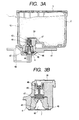
- FIG. 3A is a drawing to show the sectional structure of the black ink cartridge taken as an example.
- the ink chamber 10 stores a porous member impregnated with ink so that required negative pressure is given to ink.
- a filter 39 is placed between the ink chamber 10 and the ink supply port 4 so as to come in contact with the porous member.
- the seal material 7 is put on the outer end of the ink supply port 4 for sealing the ink supply port 4.
- a closed space 60 is formed between a valve body 49 and the seal material 7.
- a record head 40 is fixed to a carriage 41 of an ink jet recorder to which the ink cartridge is mounted, and an ink introduction member 42 is set so as to protrude on the carriage 41 and communicate with the record head 40.
- the ink introduction member 42 penetrates the seal material 7 and is joined to packing 45 in fluid-sealing relation to allow the ink chamber 10 and the record head 40 to communicate with each other.
- the ink introduction member 42 is formed as a tubular member, and has a taper part 43 at its tip portion. Through holes for allowing ink to flow in, namely, ink introduction ports 44, 44, ... are formed in the taper part 43.
- the tip end of the ink introduction member 42 is contoured to have a proper sharp-pointed shape so that tension can be given to the seal material 7 for breaking the seal material 7 when the seal material 7 on the ink supply port is pressed by the tip end.
- the packing 45 is formed at its inner peripheral surface with a taper part 43, and at its tip, i.e. the ink chamber side thereof, with a cylindrical fit part 47.
- the tip area of the ink introduction member 42 is guided by the taper part 43 until the fit part 47 is brought into tight contact with the ink introduction member 42 to secure the fluid-sealing relation.
- the valve body 49 is constantly pressed against the top of the packing 45 by the force of a spring 48 so as to close an ink flow passage.
- FIGS. 4A and 5A show embodiments of the above-described seal material 7.
- the seal material 7 is of a laminated structure including, at least, a physical protective layer 50 and an airtight hold layer 51 that are laminated together via an adhesion layer 53.
- the physical protective layer 50 is constructed by a uni-directionally drawn film that is made, for example, of polyethylene terephthalate and that has 12 ⁇ m thickness.
- the airtight hold layer 51 is constructed by a film of polypropylene or the same group as polypropylene to have 30 ⁇ m thickness.
- the films forming the physical protective layer 50 and the airtight hold layer 51 are 10 to 30 ⁇ m thick and 15 to 50 ⁇ m thick respectively.
- the seal material 7 made up of the films forming the physical protective layer 50 and the airtight hold layer 51, onto the ink supply port from the viewpoints of maintaining the quality and simplifying the process, and therefore the material of the airtight hold layer 51 contacting the ink supply port is selected considering adhesion to the container main unit 2.
- the container main unit 2 is made of polypropylene
- the film forming the airtight hold layer 51 is made of a material of polypropylene or a polypropylene group.
- the physical protective layer 50 a material that is higher in softening or melting temperature than the airtight hold layer 51 and that is excellent in handling property is selected.
- the physical protective layer 50 is formed with a slit 52 in parallel with or perpendicularly to the drawing direction of the uni-directionally drawn film forming the physical protective layer 50.
- the slit 52 is U-shaped or V-shaped in cross section, as shown in FIG. 5A. Forming the slit 52 into the V-shape in cross section enhances a cleaving or tearing property, and it is desirable that open angle ⁇ is 60 degrees or less, preferably 30 degrees or less.
- the slit 52 shown in Fig. 4A has a flat bottom.
- the deeper slit 52 is desirable, but the deeper slit 52 will hinder the handling property because a breakage may occur during a winding step or fused adhesion step of assembling process. Therefore, in view of this, it is preferable that the airtight hold layer 51 is made a slightly thicker and the slit 52 is made in a depth to such an extent that the tip of the slit 52 slightly reaches the airtight hold layer 51, as shown in FIGS. 4B and 5B.
- the slit(groove) 52 of the seal material 7 can be easily formed such that, after the physical protective layer 50 and the airtight hold layer 51 are laminated together via the thin adhesion layer 53, a cutter preferably having a tip angle of 30 degrees or less is depressed to a predetermined depth from the face of the physical protective layer 50.
- the slit 52 can also be formed such that, after a cutting tool is set at a depth of the slit to be formed, the seal material 7 is relatively moved. Further, the physical protective layer 50 may be previously formed with the slit 52 by a press, etc., and then be laminated on the airtight hold layer 51. According to this process, although a cleaving assisting recess (slit) cannot be formed to reach the airtight hold layer 51, it is advantageously dispensed with depth management of the cutting tool in forming the slit.
- the seal material 7 may be formed by uni-directionally drawn polyethylene terephthalate and uni-directionally drawn polypropylene which are laminated so that their drawing directions are parallel or orthogonal to each other.
- At least one cleaving assisting slit 57 is formed, as shown in FIG. 2B, to extend in the direction in which the ink supply ports 28 to 32 are arranged, and to pass through the ink supply ports 28 to 32.
- a similar advantage is provided if the cleaving assisting slits 57 are separately formed for the respective ink supply ports 28 to 32, or the cleaving assisting slits 57 for the respective ink supply ports extend perpendicular to the direction in which the ink supply ports 28 to 32 are arranged.
- cleaving assisting slits 57 may be formed to be in parallel to each other or to cross each other, a single continuous slit 57 extending in the arrangement direction is preferable because the slit forming step can be simplified.
- seal material 7 is formed so as to provide a light transmission property, it is possible to visually check the state of the thermal adhesion between the seal material and the ink supply ports as well as whether or not ink leakage through the packing member or the valve occurs.
- the ink cartridge of this type is assembled in the following manner: A stainless filter 39 is fixed to the high polymeric container main unit 2 by thermal welding or thermal adhesion, and then the circuit board 6 on which the storage device is mounted is attached to the container main unit 2.
- the spring 48, the valve body 49, and the packing 45 are inserted in this order through the ink supply port 4 and assembled into the main unit 2, then the ink supply port 4 is sealed with the seal material 7.
- the seal material 7 serves as a member for not only preventing ink from leaking, but also preventing the packing 45 from being pushed out by the spring 48.
- the cleaving assisting slit 52 is aligned to a position where the tip of the ink introduction member 42 of the carriage abuts or to the proximity of the position.
- a porous member is pushed into the container main unit 2, and the lid 3 is thermally welded or thermally adhered to the container main unit 2.
- the pressure in the ink chamber is reduced so that the chamber is filled with ink.
- the ink chamber is once released to the atmosphere, but again put into the pressure-reduced condition, and in the pressure-reduced condition, the ink injection port and the ventilation hole of the lid 3 are sealed with the films 8 and 8a.
- the cartridge sealed with the films 8 and 8a is housed in a bag 66 made of a film having an air shield property, and is packed in the pressure-reduced condition.
- FIG. 6A shows one form of the black ink cartridge 1, which is a commercially available product in which the black ink cartridge 1 is packed by the bag 66 made of a film having a high air shield property.
- the cartridge 1 is distributed in this form until it is set in a printer after the cartridge 1 is manufactured. Since the ink supply port 4 projects externally from the face of the container main unit 2, the film forming the bag 66 is pushed to and closely contacted with the seal material 7 by the atmospheric pressure.
- the inner pressure of the bag 66 forming the packing is maintained in a reduced pressure state of, for example, minus 400 to minus 650 mmHG, to establish negative pressure state. Therefore, even if the ink cartridge is left for a long term in the distribution process, the dissolved air amount of ink can be decreased over time, and in the event that ink leakage accidentally occurs, the leaked ink can be stored in the bag 66 and can be prevented from leaking out to the outside and further evaporation of ink can also be suppressed.
- the packing in a reduced pressure state provides the remarkable advantage in maintaining the quality of ink in a case where the ink cartridge is stored or left for a long term.
- Forming the bag 66 for reduced pressure packing, of such a material as to enable visual check of the inside makes it possible to easily and visually check ink leakage in a long-term storage state. That is, a user can preliminarily know the presence or absence of ink leakage prior to opening the bag. This is very useful in maintaining the quality of the cartridge, particularly, the cartridge of the invention having the valve mechanism.
- FIGS. 7 and 8 show the process of mounting an ink cartridge by taking the black ink cartridge 1 as an example.
- the packing bag 66 is opened, the ink cartridge 1 is taken out therefrom, and the film 8a sealing the ventilation hole of the lid 3 is peeled off, then a lever 58 of a cartridge holder 65 of the carriage is opened and the cartridge 1 is loaded.
- a protruded part 11 of the ink cartridge 1 is received by a projection 14 of the lever 58 and an opposite end is supported on a slope part 13b of the cartridge holder 65.
- the hook part 16 and the lever 58 are disengaged, then the lever 58 is rotated upward, whereby the ink cartridge 1 is pulled up by the lever 58 and the ink supply port 4 is detached from the ink introduction member 42. If the lever 58 is further rotated, the upper half of the ink cartridge 1 is exposed from the holder 65. Thus, the ink cartridge 1 can be easily removed from the holder 65.
- tip 42a of the ink introduction member 42 abuts the cleaving assisting slit 52 of the seal material 7 directly or the proximity of the cleaving assisting slit 52.
- the seal material 7 whose periphery is fixed by thermal adhesion receives tension by the tip 42a of the ink introduction member 42, so that a stress concentration occurs at the abutment part, and the seal material 7 is cleaved along the slit 52 having a weak strength spontaneously (FIG. 9B).
- the air A flows out or flows in through the cleaved part in such a manner that the space 60 is released to the atmosphere with the air flow not directly hitting the ink introduction ports 44 of the ink introduction member 42.
- the fit part 47 of the packing 45 is fitted to the ink introduction member 42, and the valve body 49 is pushed and opened, allowing the ink chamber 10 to communicate with the record head 40.
- the state in which ink can be supplied to the record head 40 is established.
- seal material 7 is high in cleaving property in the direction along the drawing direction, use of uni-directionally drawn film for the seal material on the ink supply port 4 is very effective, and forming the cleaving assisting slit 52 in parallel with the drawing direction is useful means for furthermore enhancing the effect.
- the ink supply port 4 is formed into a circle shape, and the seal material 7 is fixed to the entire periphery of the ink supply port 4 by thermal adhesion. Therefore, the seal material 7 is fixed with an adequate tension.
- the seal material 7 is cleaved rapidly with a long distance without producing slack or peeling as the slit 52 serves as a breakage induction part when the ink introduction member 42 is pushed.
- the ink introduction member 100 elastically deforms the seal material 101 largely to compress air in the space 102 between the seal material 101 and the valve body 104 as shown in FIG. 26.
- the seal material 101 is broken at the stage where the compression proceeds. In this state, the seal material 101 is in tightly contact with the ink introduction member 100 and thus compressed air flows into the ink introduction port 103.
- FIGS. 10A, 10B 10C, 11A, 11B and 11C show other embodiments of seal material 7.
- the seal material 7 has, at least, a plurality of physical protective layers (in the embodiment, two physical protective layers 54 and 55) and an airtight hold layer 51 that are laminated together via adhesion layers 56 and 53.
- the physical protective layers 54 and 55 are laminated so that the drawing directions of uni-directionally drawn films of polyethylene terephthalate 12 ⁇ m thick, for example, are parallel or orthogonal to each other.
- One physical protective layer is added, and the cleaving assisting slit 52, 52' U-shaped or V-shaped in cross section is formed to penetrate the two physical protective layers 54 and 55. This arrangement can enhance the entire rigidity of the physical protective layers 54 and 55 without degrading the cleaving property, thereby preventing the seal material 7 from curling. Therefore, the handling property can be improved, and the airtight hold layer 51 can be protected.
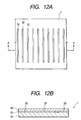
- FIGS. 12 and 13 show examples of how the cleaving assisting slits are arranged in the seal material 7.
- a plurality of linear and continuous cleaving assisting slits 52 of the physical protective layer 50 are arranged in parallel to one another at given pitches of, for example, about 1 mm.
- a plurality of short slits 52 are formed on a single line, and plural sets of the short slits 52 are arranged in parallel to one another at given pitches of, for example, about 1 mm.
- the seal material 7 thus formed is cut to have the required shape and size, and thermally adhered to the peripheral portion of the ink supply port. From the viewpoint of adhesion or the like, it is desirable that the arrangement of the slits 52 and the length of each slit 52 are so selected that the slits 52 do not exist in the peripheral portion 4a of the ink supply port 4, as shown in FIGS. 14A and 14B.
- the seal material can be broken at positions away from the ink introduction member and an air flow can be prevented from hitting the ink introduction member.
- the seal material 7 sealing the ink supply port 4 includes a unidirectionally drawn film, and a long cleaving part is formed using the ink introduction member 42.
- a projection 61 or 61' having a sharp tip may be formed to protrude in the direction toward the peripheral portion 4a of the ink supply port 4 or in the direction toward the center of the ink supply port 4.
- the projection 61 or 61' can be easily provided such that, as shown in FIGS. 15B and 16B, an annular base 62 having the projection 61 or 61' protruding from the surface or toward the center is disposed outside the packing 45.
- FIGS. 17A and 17B show another embodiment having means for first breaking the seal material 7 in an area away from the ink introduction member 42.
- a reinforcing material 67 is fixed to the outside of the seal material 7.
- the size of the reinforcing material 67 is so selected as to coveringly extend to an area slightly outer than an area where the ink introduction member 42 abuts. That is, the reinforcing material covers an area of the seal material 7 so as to prevent the air ejected in conjunction with the breakage of the seal material 7 from being directly hit onto the ink introduction port 44.
- the reinforcing material 67 is higher in rigidity than the seal material 7.
- the ink cartridge 1 is further pushed so that the seal material 7 is broken at a peripheral edge of the reinforcing material 67, i.e. at a position away from the ink introduction member 42, as shown in FIG. 18B. Therefore, the air in the space 60 of the ink supply port 4 is released before the ink introduction port 44 engages the packing 45 in fluid-sealing relation.
- the seal material 7 can be broken to release the space 60 of the ink supply port 4 to the atmosphere without entering air into the ink introduction port 44 of the ink introduction member 42, regardless of the shape of the tip of the ink introduction member 42, regardless of the characteristic of the seal material 7, namely, whether or not the seal material has a uni-directionally drawn property, and regardless of the presence or absence of the slit 52.
- FIG. 19 shows one embodiment of the ink introduction member, which is applicable to the above-described breaking technique of the seal material 7.
- the ink introduction member is formed into a truncated conical shape to have a flat part 42b at its tip end.
- the flat part 42b is pressed to the seal material 7 to apply a tension to the seal material 7, thereby breaking the seal material 7 at a position away from the ink introduction ports 44 with the aid of the slit 52, the projection 61, 61', the reinforcing material 67, etc.
- FIGS. 20 and 21 show embodiments of the ink introduction member, which are appropriate for breaking the seal material 7 without allowing air in the space 60 of the ink supply port 4 to flow into the ink introduction port 44 regardless of property of the seal material.
- At least one groove 42c is formed on the surface of the ink introduction member 42.
- the groove 42c extends from the proximity of the tip 42a of the ink introduction member 42, i.e. from a position ahead of the ink introduction port 44, toward the proximal end of the ink introduction member 42.
- a sharp-pointed part 42d is formed so as to project to the tip side ahead of the ink introduction port 44. Since the seal material is broken by the sharp-pointed part 42d before the ink introduction port 44 below the sharp-pointed part 42d is fitted to the packing 45, air compressed in the space 60 can also be prevented from entering the ink introduction port 44.
- the seal material is broken to release air before the ink introduction port 44 of the ink introduction member 42 is fitted to the packing 55, but the volume of the space 60 may be decreased.
- FIG. 22 shows one embodiment in which the volume of the space 60 formed by the packing 45 and the seal material 7 can be reduced to be minimal.
- the seal material 7 is formed with cup-shaped convex parts 7a, each corresponding in shape to the taper part 43 and fit part 47 of the packing 45, as shown in FIGS. 23A and 23B.
- the tip of the ink introduction member 42 when the tip of the ink introduction member 42 is deeply inserted into the packing 45, the tip of the ink induction member 42 abuts the seal material 7, as shown in FIG. 22B.
- the seal material 7 is elastically deformed, air in the space 60 is not excessively compressed, and air can be prevented from entering from the ink introduction port 44.
- the ink introduction member 42 comes in elastic contact with a thinnest part 45a of the packing 45 and then passes through the thinnest part 45a, the seal material 7 is prevented from being bitten into the thinnest part 45a, and the ink introduction member 42 and the packing 45 are maintained in fluid-sealing relation.
- a projection 72 may be provided at a point of the recorder normally covered with a cover 71 and opened only when an ink cartridge is replaced, as shown in FIG. 24.
- the ink cartridge is taken out from the bag 66 (FIG. 6), and then the ink supply port 4 of the cartridge is pressed to the projection 72 to preliminarily break the seal material using the projection 72 prior to the mounting of the cartridge. Thereafter, the ventilation hole film 8a on the lid is peeled off, and then the cartridge is mounted to a cartridge holder 73. After the ventilation hole film 8a is peeled off, the seal material 7 may be broken using the projection 72, and the cartridge may be mounted.
- the ink cartridge can be mounted without entering air in the ink supply member, without requiring a structure for inducing a breakage on the seal material of the ink cartridge or the ink introduction member of the recorder.
- the cartridge to be mounted in the vertical direction is taken as an example, but the invention can also be applied to an ink cartridge 1 with an ink supply port 4 formed in a vertical wall 1b, as shown in FIG. 25.
- a breakage induction part is provided to the seal material or the proximity of the ink supply port.
- the seal material is broken to release the space closed by the ink passage open/close section and the seal material to the atmosphere, and then the ink introduction member is inserted into the ink supply port in fluid-sealing relation. Therefore, the air is prevented from entering the ink introduction port.
Landscapes
- Ink Jet (AREA)
Abstract
Description
Claims (33)
- An ink cartridge comprising;a container storing ink therein;an ink supply port into which an ink introduction member communicating with a record head is to be inserted;an ink passage open/close section that is opened and closed as the ink introduction member is advanced and retreated to and from the ink supply port;a seal material sealing the ink supply port; anda breakage induction part provided to the seal material or a proximity of the ink supply port.
- An ink cartridge comprising:a container storing ink therein;an ink supply port into which an ink introduction member communicating through an ink introduction port with a record head is to be inserted;an ink passage open/close section that is opened and closed as the ink introduction member is advanced and retreated to and from the ink supply port; anda seal material that seals the ink supply port and that is first broken with the aid of a breakage induction part, wherein, after the seal material is broken using the ink introduction member to release a space closed by said ink passage open/close section and the seal material to the atmosphere, the ink introduction port communicates with the ink supply port.
- The ink cartridge as claimed in claim 1 or 2, wherein the breakage induction part is formed by discontinuously changing a thickness of the seal material in a proximity of an area where the ink introduction member abuts.
- The ink cartridge as claimed in claim 1 or 2, wherein the breakage induction part includes at least one recess provided to a side of the seal material where the ink introduction member abuts.
- The ink cartridge as claimed in claim 4, wherein the at least one recess is disposed within an inner area surrounded by a peripheral portion of said ink supply port.
- The ink cartridge as claimed in claim 4 or 5, wherein a bottom of the recess is formed into a V shape in cross section.
- The ink cartridge as claimed in claim 4, wherein the at least one recess extends across the ink supply port.
- The ink cartridge as claimed in any of claims 1 to 7, wherein the seal material is constructed by at least one uni-directionally drawn film.
- The ink cartridge as claimed in claim 8, wherein the seal material has a laminated construction of plural films including the at least one uni-directionally drawn film, and a slit is formed as the recess so that a bottom of the slit is located in one of films, which contacts the ink supply port.
- The ink cartridge as claimed in claim 1 or 2, wherein the breakage induction part includes a highly rigid part that is not broken by the ink introduction member and that is located to cover an area of the seal material where the ink introduction member abuts, and wherein the seal material is first broken in an area where the highly rigid part is not formed as the ink introduction member abuts the highly rigid part.
- The ink cartridge as claimed in claim 1 or 2, wherein the breakage induction part includes a projection that is provided in an area where the seal material abuts when the seal material is pressed by the ink introduction member.
- An ink cartridge comprising:a container storing ink therein;in ink supply port into which an ink introduction member communicating with a record head is to be inserted;an ink passage open/close section that is opened and closed as the ink introduction member is advanced and retreated to and from the ink supply port;a seal material sealing the ink supply port; anda projection provided in an area where the seal material abuts when the seal material is pressed by the ink introduction member.
- The ink cartridge as claimed in claim 11 or 12, wherein the projection is protruded toward the seal material or toward a center of the ink supply port.
- The ink cartridge as claimed in any one of claims 1 to 13, wherein the ink supply port is tubular, and the seal material is thermally adhered to a peripheral portion of the ink supply port.
- The ink cartridge as claimed in claim 1, 2, 11 or 12, wherein the seal material is constructed by at least one light-transmissible film.
- The ink cartridge as claimed in claim 1, 2, 11 or 12, wherein the seal material has a layered construction of at least a physical protective layer and an airtight hold layer.
- The ink cartridge as claimed in claim 1, 2, 11 or 12, wherein the ink passage open/close section includes a valve body that is constantly urged by an elastic member to the ink supply port to close a flow passage and that is retreated as the ink introduction member is advanced to open the flow passage.
- An ink cartridge as claimed in anyone of the proceeding claims, wherein the ink cartridge is packaged by an air shield film to maintain a pressure-reduced state.
- The ink cartridge as claimed in claim 18, wherein the ink supply port projects externally from a wall of the container, and the air shield film is closely contacted with the seal material using the atmospheric pressure to press the seal material toward the ink supply port.
- The ink cartridge as claimed in claim 18 or 19, wherein the air shield film has a light transmission property at least in an area where the ink supply port is located.
- An ink cartridge comprising:a container storing ink therein;an ink supply port into which an ink introduction member communicating with a record head is to be inserted;an ink passage open/close section that is opened and closed as the ink introduction member is advanced and retreated to and from the ink supply port; anda seal material that seals the ink supply port and that has a cup-shaped convex part to fill a space of the ink supply port.
- The ink cartridge as claimed in claim 21, wherein the convex part is contacted with an inner peripheral surface of a packing attached to the ink supply port.
- The ink cartridge as claimed in claim 22, wherein a clearance is formed between a distal end of the convex part and the packing.
- An ink cartridge comprising:a container divided into a plurality of chambers by a partition wall or partition walls;a plurality of ink supply ports that communicate respectively with the chambers, and that are arranged along a single line;a single seal material that seals the ink supply ports and that has at least one slit extending in a direction in which the ink supply ports are arranged.
- The ink cartridge as claimed in claim 24, wherein the seal material has a layered construction of at least a physical protective layer and an airtight hold layer.
- The ink cartridge as claimed in claim 16, 24 or 25, wherein the airtight hold layer is formed by at least one film that is made of a polymeric material, and as dependent on claim 24 or 25 wherein the polymeric material is the same as or similar in group to a polymeric material forming the container.
- A recorder comprising:a record head; andan ink introduction member having an ink introduction port communicating with the record head so that ink is supplied from an ink cartridge through the ink introduction member to the record head, wherein:upon breakage of a seal material sealing an ink supply port of the ink cartridge by the ink introduction member, ink in the ink cartridge can flow into the record heads through the introduction member.
- The recorder as claimed in claim 27, wherein the ink introduction member is formed at its side surface with an air flow-out groove that extends to a more distal side than the ink introduction port.
- The recorder as claimed in claim 27 or 28, wherein the ink introduction member is provided, at a more distal side than the ink introduction port, with a sharp-pointed part for breaking the seal material.
- The recorder as claimed in claim 27 or 28, wherein the seal material is formed with a breakage induction part by discontinuously changing a thickness of the seal material in a proximity of an area where the ink introduction member abuts, and the ink introduction member is formed at its distal end with a flat part.
- The recorder as claimed in claim 27, wherein a projection for preliminary breaking the seal material is formed on a housing of the recorder.
- A method of mounting an ink cartridge for connection to an ink introduction member communicating with a record head, the ink cartridge comprising an ink chamber storing ink therein, a ventilation hole communicating the ink chamber with atmosphere, an ink supply port communicated with the ink chamber via a filter, an ink passage open/close section disposed between the ink supply port and the ink chamber, and a seal material sealing the ink supply port, the ink cartridge being packaged by a pressure-reduced packing material, the method comprising the steps of:taking out the ink cartridge from the pressure-reduced packing material;breaking the seal material to release a space between the seal material and the ink passage open/close section to the atmosphere; andopening the ink passage open/close section to communicate the ink chamber with the record head.
- The method as claimed in claim 32, wherein the step of breaking the seal material is performed before or after releasing the ventilation hole to the atmosphere.
Applications Claiming Priority (6)
| Application Number | Priority Date | Filing Date | Title |
|---|---|---|---|
| JP28762999 | 1999-10-08 | ||
| JP28762999 | 1999-10-08 | ||
| JP31745099 | 1999-11-08 | ||
| JP31745099 | 1999-11-08 | ||
| JP2000299196A JP2001199082A (en) | 1999-10-08 | 2000-09-29 | INK CARTRIDGE, INK JET RECORDING DEVICE, AND METHOD OF MOUNTING INK CARTRIDGE |
| JP2000299196 | 2000-09-29 |
Publications (3)
| Publication Number | Publication Date |
|---|---|
| EP1090767A2 true EP1090767A2 (en) | 2001-04-11 |
| EP1090767A3 EP1090767A3 (en) | 2001-05-30 |
| EP1090767B1 EP1090767B1 (en) | 2003-02-05 |
Family
ID=27337368
Family Applications (1)
| Application Number | Title | Priority Date | Filing Date |
|---|---|---|---|
| EP00121337A Expired - Lifetime EP1090767B1 (en) | 1999-10-08 | 2000-10-09 | Ink cartridge, ink jet recorder, and method of mounting ink cartridge |
Country Status (6)
| Country | Link |
|---|---|
| US (1) | US6554412B1 (en) |
| EP (1) | EP1090767B1 (en) |
| JP (1) | JP2001199082A (en) |
| AT (1) | ATE232167T1 (en) |
| DE (1) | DE60001344T2 (en) |
| ES (1) | ES2192164T3 (en) |
Cited By (17)
| Publication number | Priority date | Publication date | Assignee | Title |
|---|---|---|---|---|
| DE10216654A1 (en) * | 2002-04-15 | 2003-10-23 | Artech Gmbh Design & Prod | Inkjet cartridge has an improved sealing mechanism for the ink outlet with a cover that has an indentation coaxial with the outlet sealing means to ensure that an ink removal needle is automatically centered in the seal |
| EP1306218A3 (en) * | 2001-10-25 | 2003-11-12 | Hewlett-Packard Company | Fluid interconnect port seal with lock-out tab |
| US6676252B2 (en) | 2002-04-24 | 2004-01-13 | Hewlett-Packard Development Company, L.P. | Printer ink cartridge and method of assembling same |
| WO2006116698A3 (en) * | 2005-04-27 | 2006-12-14 | Hewlett Packard Development Co | Sealing component defining first, second, and third seals |
| EP1955852A1 (en) * | 2007-02-07 | 2008-08-13 | Seiko Epson Corporation | Fluid container,recycling method of fluid container, and sealing method of fluid container |
| EP2014473A1 (en) * | 2007-06-08 | 2009-01-14 | Powerful Way Limited | Inc cartridge for inkjet printers |
| EP1092546B1 (en) * | 1999-10-12 | 2009-06-24 | Seiko Epson Corporation | Ink cartridge for ink-jet printing apparatus |
| CN101186150B (en) * | 2006-11-22 | 2010-07-21 | 精工爱普生株式会社 | liquid injection device |
| EP2314454A3 (en) * | 2009-10-22 | 2011-05-04 | Ricoh Company, Ltd. | Liquid container and image forming apparatus including the liquid container |
| WO2012086381A1 (en) * | 2010-12-20 | 2012-06-28 | Fujifilm Corporation | Printing liquid container, printing liquid filled container, image forming apparatus and printing liquid filled container manufacturing method |
| US8217491B2 (en) | 2009-10-02 | 2012-07-10 | Ricoh Company, Ltd. | Semiconductor device |
| CN102642406A (en) * | 2011-02-18 | 2012-08-22 | 富士胶片株式会社 | Image forming liquid cartridge and image forming apparatus |
| CN104057712A (en) * | 2013-03-22 | 2014-09-24 | 兄弟工业株式会社 | Print Fluid Cartridge Having Print Fluid Supply Portion, And Print Fluid Supplying Apparatus |
| EP2927001A3 (en) * | 2012-05-23 | 2016-12-07 | Seiko Epson Corporation | Cover and liquid container |
| US9649847B2 (en) | 2012-07-23 | 2017-05-16 | Seiko Epson Corporation | Cartridge |
| US9776418B2 (en) | 2012-07-23 | 2017-10-03 | Seiko Epson Corporation | Method and apparatus for manufacturing cartridge |
| US10384454B2 (en) | 2012-07-23 | 2019-08-20 | Seiko Epson Corporation | Refilled cartridge and method for manufacturing refilled cartridge |
Families Citing this family (41)
| Publication number | Priority date | Publication date | Assignee | Title |
|---|---|---|---|---|
| JP4029264B2 (en) * | 2001-11-14 | 2008-01-09 | セイコーエプソン株式会社 | Ink tank |
| ES2275603T5 (en) | 2000-10-20 | 2010-07-07 | Seiko Epson Corporation | INJECTION RECORD DEVICE FOR INK AND INK CARTRIDGE. |
| KR100487976B1 (en) | 2000-10-20 | 2005-05-10 | 세이코 엡슨 가부시키가이샤 | Ink cartridge for ink jet recording device |
| CA2379725C (en) | 2001-04-03 | 2007-06-12 | Seiko Epson Corporation | Ink cartridge |
| JP3666491B2 (en) | 2002-03-29 | 2005-06-29 | セイコーエプソン株式会社 | Ink cartridge and recording apparatus |
| US20030184625A1 (en) * | 2002-04-02 | 2003-10-02 | Pui Kuong Lui | Ink cartridge |
| US6986571B2 (en) * | 2002-04-23 | 2006-01-17 | Hewlett-Packard Development Company, L.P. | Filter for a print cartridge |
| ES2303151T3 (en) | 2002-11-26 | 2008-08-01 | Seiko Epson Corporation | INK CARTRIDGE. |
| SG165983A1 (en) * | 2002-11-26 | 2010-11-29 | Seiko Epson Corp | Ink cartridge and recording apparatus |
| JP3624950B2 (en) | 2002-11-26 | 2005-03-02 | セイコーエプソン株式会社 | ink cartridge |
| ATE528141T1 (en) * | 2003-03-05 | 2011-10-15 | Seiko Epson Corp | METHOD FOR PRODUCING A LIQUID CONTAINER |
| JP4096923B2 (en) * | 2003-08-20 | 2008-06-04 | セイコーエプソン株式会社 | Liquid conducting material and liquid ejecting apparatus |
| JP4506301B2 (en) * | 2003-09-30 | 2010-07-21 | ブラザー工業株式会社 | Ink cartridge and inkjet printer |
| JP4513337B2 (en) * | 2004-01-23 | 2010-07-28 | セイコーエプソン株式会社 | ink cartridge |
| JP4325437B2 (en) * | 2004-03-01 | 2009-09-02 | ソニー株式会社 | Logistics method for liquid discharge head |
| US20050206693A1 (en) * | 2004-03-22 | 2005-09-22 | Stephen Chen | High capacity ink supply apparatus |
| JP5022576B2 (en) * | 2005-07-08 | 2012-09-12 | 株式会社ジャパンディスプレイイースト | Display panel and display device |
| JP4844100B2 (en) * | 2005-11-28 | 2011-12-21 | ブラザー工業株式会社 | Ink cartridge manufacturing method |
| JP4854281B2 (en) * | 2005-11-29 | 2012-01-18 | キヤノン株式会社 | Recording head, ink tank, and manufacturing method of recording head |
| US7837297B2 (en) | 2006-03-03 | 2010-11-23 | Silverbrook Research Pty Ltd | Printhead with non-priming cavities for pulse damping |
| CN101287606B (en) * | 2006-03-03 | 2010-11-03 | 西尔弗布鲁克研究有限公司 | Pulse Damping Jet Structure |
| WO2007142263A1 (en) * | 2006-06-06 | 2007-12-13 | S.T. Sangyo Co., Ltd. | Ink cartridge and method for recycling ink cartridge |
| US7950790B2 (en) * | 2006-09-11 | 2011-05-31 | Canon Kabushiki Kaisha | Ink container and ink jet recording apparatus |
| JP5003872B2 (en) * | 2007-01-18 | 2012-08-15 | セイコーエプソン株式会社 | Liquid ejector |
| EP1925456A3 (en) | 2006-11-22 | 2009-08-26 | Seiko Epson Corporation | Liquid-jet apparatus |
| JP4915515B2 (en) * | 2007-01-17 | 2012-04-11 | セイコーエプソン株式会社 | Liquid ejector |
| US7419254B1 (en) | 2007-01-30 | 2008-09-02 | Brother Kogyo Kabushiki Kaisha | Ink cartridges |
| JP2008230214A (en) * | 2007-02-19 | 2008-10-02 | Seiko Epson Corp | Seal structure for fluid outlet and sealing method, fluid container, refill fluid container, and refill method thereof |
| US8322835B2 (en) * | 2007-02-19 | 2012-12-04 | Seiko Epson Corporation | Sealing structure of fluid container, and method of manufacturing and reusing fluid container |
| US8025378B2 (en) * | 2007-03-28 | 2011-09-27 | Brother Kogyo Kabushiki Kaisha | Ink cartridges |
| JP5046889B2 (en) * | 2007-11-29 | 2012-10-10 | キヤノン株式会社 | Recording device |
| US8468635B2 (en) * | 2009-11-25 | 2013-06-25 | Church & Dwight Co., Inc. | Surface treating device |
| WO2011132651A1 (en) * | 2010-04-22 | 2011-10-27 | ジット株式会社 | Valve mechanism, ink control mechanism, ink storage container |
| JP5619469B2 (en) * | 2010-04-22 | 2014-11-05 | ジット株式会社 | Valve mechanism, ink storage container |
| US9421781B2 (en) * | 2012-10-15 | 2016-08-23 | Seiko Epson Corporation | Recording apparatus |
| WO2017115584A1 (en) * | 2015-12-28 | 2017-07-06 | セイコーエプソン株式会社 | Liquid supply unit |
| CN108566776A (en) * | 2015-12-28 | 2018-09-21 | 精工爱普生株式会社 | Fluid supply unit |
| JP2020104440A (en) * | 2018-12-28 | 2020-07-09 | セイコーエプソン株式会社 | Printers and cartridges |
| JP2020114654A (en) * | 2019-01-18 | 2020-07-30 | セイコーエプソン株式会社 | Seal structure and liquid storage container |
| JP7292910B2 (en) * | 2019-03-19 | 2023-06-19 | キヤノン株式会社 | Liquid storage container, liquid ejection head, and liquid ejection device |
| JP2023051714A (en) * | 2021-09-30 | 2023-04-11 | セイコーエプソン株式会社 | Ink supply container |
Family Cites Families (20)
| Publication number | Priority date | Publication date | Assignee | Title |
|---|---|---|---|---|
| US3941171A (en) * | 1973-07-05 | 1976-03-02 | Ims Limited | Fluid transfer device |
| JPS5074341A (en) | 1973-10-31 | 1975-06-19 | ||
| JPS639546A (en) * | 1986-07-01 | 1988-01-16 | Canon Inc | ink supply device |
| JPH0811448B2 (en) * | 1986-07-02 | 1996-02-07 | キヤノン株式会社 | Inkjet cartridge |
| US5844578A (en) * | 1990-01-30 | 1998-12-01 | Seiko Epson Corporation | Ink-jet recording apparatus and ink tank cartridge thereof |
| JPH04214360A (en) * | 1990-12-10 | 1992-08-05 | Canon Inc | Ink jet recording device, ink tank cartridge for said device and manufacture of said cartridge |
| JP3005104B2 (en) | 1992-02-24 | 2000-01-31 | キヤノン株式会社 | Liquid storage container, recording head unit having the liquid storage container, and recording apparatus equipped with the liquid storage container |
| CA2272165C (en) * | 1992-07-31 | 2003-10-14 | Canon Kabushiki Kaisha | Liquid storing container for recording apparatus |
| US5754207A (en) * | 1992-08-12 | 1998-05-19 | Hewlett-Packard Company | Volume indicating ink reservoir cartridge system |
| GB2279043B (en) * | 1992-09-10 | 1997-03-26 | Seiko Epson Corp | Printer |
| ES2119021T3 (en) * | 1993-05-25 | 1998-10-01 | Canon Kk | PACKAGING CASE AND METHOD FOR OPENING THE SAME. |
| GB2315462B (en) * | 1994-09-16 | 1998-05-06 | Seiko Epson Corp | Ink tank cartridge for a printer or the like |
| JPH08174860A (en) * | 1994-10-26 | 1996-07-09 | Seiko Epson Corp | Ink cartridge for inkjet printer |
| US5825387A (en) * | 1995-04-27 | 1998-10-20 | Hewlett-Packard Company | Ink supply for an ink-jet printer |
| US5777646A (en) * | 1995-12-04 | 1998-07-07 | Hewlett-Packard Company | Self-sealing fluid inerconnect with double sealing septum |
| EP0927641B1 (en) * | 1994-11-02 | 2002-03-13 | Seiko Epson Corporation | Ink jet recording unit |
| JPH0958009A (en) * | 1995-08-23 | 1997-03-04 | Seiko Epson Corp | Ink cartridge, its packaging case, and packaging method |
| US6033141A (en) * | 1996-09-27 | 2000-03-07 | Nottingham-Spirk Design Associates, Inc. | Capless retractable sealed marking instruments |
| JPH10138507A (en) * | 1996-11-14 | 1998-05-26 | Seiko Epson Corp | Method of manufacturing ink cartridge for ink jet recording apparatus |
| JP3295366B2 (en) * | 1997-02-19 | 2002-06-24 | キヤノン株式会社 | Liquid holding container with cap, cap and liquid holding container |
-
2000
- 2000-09-29 JP JP2000299196A patent/JP2001199082A/en active Pending
- 2000-10-09 EP EP00121337A patent/EP1090767B1/en not_active Expired - Lifetime
- 2000-10-09 AT AT00121337T patent/ATE232167T1/en not_active IP Right Cessation
- 2000-10-09 ES ES00121337T patent/ES2192164T3/en not_active Expired - Lifetime
- 2000-10-09 DE DE60001344T patent/DE60001344T2/en not_active Expired - Lifetime
- 2000-10-10 US US09/684,789 patent/US6554412B1/en not_active Expired - Fee Related
Cited By (32)
| Publication number | Priority date | Publication date | Assignee | Title |
|---|---|---|---|---|
| EP1092546B1 (en) * | 1999-10-12 | 2009-06-24 | Seiko Epson Corporation | Ink cartridge for ink-jet printing apparatus |
| EP1306218A3 (en) * | 2001-10-25 | 2003-11-12 | Hewlett-Packard Company | Fluid interconnect port seal with lock-out tab |
| DE10216654A1 (en) * | 2002-04-15 | 2003-10-23 | Artech Gmbh Design & Prod | Inkjet cartridge has an improved sealing mechanism for the ink outlet with a cover that has an indentation coaxial with the outlet sealing means to ensure that an ink removal needle is automatically centered in the seal |
| US6676252B2 (en) | 2002-04-24 | 2004-01-13 | Hewlett-Packard Development Company, L.P. | Printer ink cartridge and method of assembling same |
| CN101166629B (en) * | 2005-04-27 | 2010-06-02 | 惠普开发有限公司 | Seal member defining first, second and third seals |
| WO2006116698A3 (en) * | 2005-04-27 | 2006-12-14 | Hewlett Packard Development Co | Sealing component defining first, second, and third seals |
| US7533976B2 (en) | 2005-04-27 | 2009-05-19 | Hewlett-Packard Development Company, L.P. | Sealing component defining first, second, and third seals |
| US7669995B2 (en) | 2005-04-27 | 2010-03-02 | Hewlett-Packard Development Company, L.P. | Sealing component defining first, second, and third seals |
| CN101186150B (en) * | 2006-11-22 | 2010-07-21 | 精工爱普生株式会社 | liquid injection device |
| EP1955852A1 (en) * | 2007-02-07 | 2008-08-13 | Seiko Epson Corporation | Fluid container,recycling method of fluid container, and sealing method of fluid container |
| US8091996B2 (en) | 2007-02-07 | 2012-01-10 | Seiko Epson Corporation | Fluid container, recycling method of fluid container, and sealing method of fluid container |
| EP2014473A1 (en) * | 2007-06-08 | 2009-01-14 | Powerful Way Limited | Inc cartridge for inkjet printers |
| US8217491B2 (en) | 2009-10-02 | 2012-07-10 | Ricoh Company, Ltd. | Semiconductor device |
| EP2314454A3 (en) * | 2009-10-22 | 2011-05-04 | Ricoh Company, Ltd. | Liquid container and image forming apparatus including the liquid container |
| US8388119B2 (en) | 2009-10-22 | 2013-03-05 | Ricoh Company, Ltd. | Liquid container and image forming apparatus including the liquid container |
| WO2012086381A1 (en) * | 2010-12-20 | 2012-06-28 | Fujifilm Corporation | Printing liquid container, printing liquid filled container, image forming apparatus and printing liquid filled container manufacturing method |
| EP2655073A4 (en) * | 2010-12-20 | 2018-06-13 | FUJIFILM Corporation | Printing liquid container, printing liquid filled container, image forming apparatus and printing liquid filled container manufacturing method |
| US8888258B2 (en) | 2010-12-20 | 2014-11-18 | Fujifilm Corporation | Printing liquid container, printing liquid filled container, image forming apparatus and printing liquid filled container manufacturing method |
| CN103249570A (en) * | 2010-12-20 | 2013-08-14 | 富士胶片株式会社 | Printing liquid container, printing liquid filled container, image forming apparatus and printing liquid filled container manufacturing method |
| EP2489517A1 (en) * | 2011-02-18 | 2012-08-22 | Fujifilm Corporation | Image forming liquid cartridge and image forming apparatus |
| US8579424B2 (en) | 2011-02-18 | 2013-11-12 | Fujifilm Corporation | Image forming liquid cartridge and image forming apparatus |
| CN102642406B (en) * | 2011-02-18 | 2015-04-08 | 富士胶片株式会社 | Image forming liquid cartridge and image forming apparatus |
| CN102642406A (en) * | 2011-02-18 | 2012-08-22 | 富士胶片株式会社 | Image forming liquid cartridge and image forming apparatus |
| EP2927001A3 (en) * | 2012-05-23 | 2016-12-07 | Seiko Epson Corporation | Cover and liquid container |
| US9649847B2 (en) | 2012-07-23 | 2017-05-16 | Seiko Epson Corporation | Cartridge |
| US9776418B2 (en) | 2012-07-23 | 2017-10-03 | Seiko Epson Corporation | Method and apparatus for manufacturing cartridge |
| US9827776B2 (en) | 2012-07-23 | 2017-11-28 | Seiko Epson Corporation | Method and apparatus for manufacturing cartridge |
| US10384454B2 (en) | 2012-07-23 | 2019-08-20 | Seiko Epson Corporation | Refilled cartridge and method for manufacturing refilled cartridge |
| US10647123B2 (en) | 2012-07-23 | 2020-05-12 | Seiko Epson Corporation | Refilled cartridge and method for manufacturing refilled cartridge |
| CN104057712A (en) * | 2013-03-22 | 2014-09-24 | 兄弟工业株式会社 | Print Fluid Cartridge Having Print Fluid Supply Portion, And Print Fluid Supplying Apparatus |
| US9126415B2 (en) | 2013-03-22 | 2015-09-08 | Brother Kogyo Kabushiki Kaisha | Print fluid cartridge having print fluid supply portion, and print fluid supplying apparatus |
| CN104057712B (en) * | 2013-03-22 | 2016-04-20 | 兄弟工业株式会社 | There is printing-fluid box and the printing-fluid supply equipment of printing-fluid supply section |
Also Published As
| Publication number | Publication date |
|---|---|
| US6554412B1 (en) | 2003-04-29 |
| EP1090767B1 (en) | 2003-02-05 |
| DE60001344T2 (en) | 2003-09-11 |
| DE60001344D1 (en) | 2003-03-13 |
| ATE232167T1 (en) | 2003-02-15 |
| HK1035350A1 (en) | 2001-11-23 |
| ES2192164T3 (en) | 2003-10-01 |
| JP2001199082A (en) | 2001-07-24 |
| EP1090767A3 (en) | 2001-05-30 |
Similar Documents
| Publication | Publication Date | Title |
|---|---|---|
| US6554412B1 (en) | Ink cartridge, ink jet recorder, and method of mounting ink cartridge | |
| EP0761450B1 (en) | Ink cartridge package and packaging method | |
| KR0136964B1 (en) | Ink container, detachment method thereof, and apparatus using the container | |
| EP2216179B1 (en) | Ink cartridge, ink jet recording apparatus and set of ink cartridges | |
| JP3747134B2 (en) | Inkjet printhead cartridge storage container | |
| US6929363B2 (en) | Ink cartridge vacuum package and ink cartridge vacuum packaging method | |
| EP1177906A2 (en) | Ink cartridge | |
| JP3332795B2 (en) | Ink tank and inkjet cartridge | |
| EP1172220B1 (en) | Ink catridge | |
| US6241348B1 (en) | Package for ink cartridge and method for manufacturing the same | |
| JP2009018844A (en) | Packaging box for liquid container | |
| JP2003300330A (en) | Ink supply system, ink tank and inkjet printer | |
| HK1035350B (en) | Ink cartridge, ink jet recorder, and method of mounting ink cartridge | |
| JP3714372B2 (en) | ink cartridge | |
| US7488061B2 (en) | Ink cartridge replacement lid | |
| JP2918558B2 (en) | Recording head | |
| JP3289778B2 (en) | Ink cartridge for inkjet recording device | |
| JP3219624B2 (en) | Ink refilling device for ink tank for ink recording head | |
| JPH10329329A (en) | Ink cartridge for ink jet recorder | |
| US20250115051A1 (en) | Ink cartridge and printing apparatus | |
| JPH10258519A (en) | ink cartridge | |
| JP3133929B2 (en) | Ink tank and inkjet recording device | |
| JP3703323B2 (en) | Ink tank and manufacturing method thereof | |
| JPH10166621A (en) | Storage container for inkjet head | |
| KR100445928B1 (en) | Ink supply container placement system and ink supply container manufacturing method |
Legal Events
| Date | Code | Title | Description |
|---|---|---|---|
| PUAI | Public reference made under article 153(3) epc to a published international application that has entered the european phase |
Free format text: ORIGINAL CODE: 0009012 |
|
| AK | Designated contracting states |
Kind code of ref document: A2 Designated state(s): AT BE CH CY DE DK ES FI FR GB GR IE IT LI LU MC NL PT SE |
|
| AX | Request for extension of the european patent |
Free format text: AL;LT;LV;MK;RO;SI |
|
| PUAL | Search report despatched |
Free format text: ORIGINAL CODE: 0009013 |
|
| AK | Designated contracting states |
Kind code of ref document: A3 Designated state(s): AT BE CH CY DE DK ES FI FR GB GR IE IT LI LU MC NL PT SE |
|
| AX | Request for extension of the european patent |
Free format text: AL;LT;LV;MK;RO;SI |
|
| 17P | Request for examination filed |
Effective date: 20010716 |
|
| 17Q | First examination report despatched |
Effective date: 20011001 |
|
| AKX | Designation fees paid |
Free format text: AT BE CH CY DE DK ES FI FR GB GR IE IT LI LU MC NL PT SE |
|
| GRAG | Despatch of communication of intention to grant |
Free format text: ORIGINAL CODE: EPIDOS AGRA |
|
| GRAG | Despatch of communication of intention to grant |
Free format text: ORIGINAL CODE: EPIDOS AGRA |
|
| GRAH | Despatch of communication of intention to grant a patent |
Free format text: ORIGINAL CODE: EPIDOS IGRA |
|
| GRAH | Despatch of communication of intention to grant a patent |
Free format text: ORIGINAL CODE: EPIDOS IGRA |
|
| GRAA | (expected) grant |
Free format text: ORIGINAL CODE: 0009210 |
|
| AK | Designated contracting states |
Designated state(s): AT BE CH CY DE DK ES FI FR GB GR IE IT LI LU MC NL PT SE |
|
| PG25 | Lapsed in a contracting state [announced via postgrant information from national office to epo] |
Ref country code: BE Free format text: LAPSE BECAUSE OF FAILURE TO SUBMIT A TRANSLATION OF THE DESCRIPTION OR TO PAY THE FEE WITHIN THE PRESCRIBED TIME-LIMIT Effective date: 20030205 Ref country code: GR Free format text: LAPSE BECAUSE OF FAILURE TO SUBMIT A TRANSLATION OF THE DESCRIPTION OR TO PAY THE FEE WITHIN THE PRESCRIBED TIME-LIMIT Effective date: 20030205 Ref country code: FI Free format text: LAPSE BECAUSE OF FAILURE TO SUBMIT A TRANSLATION OF THE DESCRIPTION OR TO PAY THE FEE WITHIN THE PRESCRIBED TIME-LIMIT Effective date: 20030205 |
|
| REG | Reference to a national code |
Ref country code: GB Ref legal event code: FG4D |
|
| REG | Reference to a national code |
Ref country code: CH Ref legal event code: NV Representative=s name: BOVARD AG PATENTANWAELTE Ref country code: CH Ref legal event code: EP |
|
| REG | Reference to a national code |
Ref country code: IE Ref legal event code: FG4D |
|
| REF | Corresponds to: |
Ref document number: 60001344 Country of ref document: DE Date of ref document: 20030313 Kind code of ref document: P |
|
| PG25 | Lapsed in a contracting state [announced via postgrant information from national office to epo] |
Ref country code: PT Free format text: LAPSE BECAUSE OF FAILURE TO SUBMIT A TRANSLATION OF THE DESCRIPTION OR TO PAY THE FEE WITHIN THE PRESCRIBED TIME-LIMIT Effective date: 20030505 Ref country code: SE Free format text: LAPSE BECAUSE OF FAILURE TO SUBMIT A TRANSLATION OF THE DESCRIPTION OR TO PAY THE FEE WITHIN THE PRESCRIBED TIME-LIMIT Effective date: 20030505 Ref country code: DK Free format text: LAPSE BECAUSE OF FAILURE TO SUBMIT A TRANSLATION OF THE DESCRIPTION OR TO PAY THE FEE WITHIN THE PRESCRIBED TIME-LIMIT Effective date: 20030505 |
|
| REG | Reference to a national code |
Ref country code: ES Ref legal event code: FG2A Ref document number: 2192164 Country of ref document: ES Kind code of ref document: T3 |
|
| PG25 | Lapsed in a contracting state [announced via postgrant information from national office to epo] |
Ref country code: IE Free format text: LAPSE BECAUSE OF NON-PAYMENT OF DUE FEES Effective date: 20031009 Ref country code: CY Free format text: LAPSE BECAUSE OF FAILURE TO SUBMIT A TRANSLATION OF THE DESCRIPTION OR TO PAY THE FEE WITHIN THE PRESCRIBED TIME-LIMIT Effective date: 20031009 Ref country code: LU Free format text: LAPSE BECAUSE OF NON-PAYMENT OF DUE FEES Effective date: 20031009 Ref country code: AT Free format text: LAPSE BECAUSE OF NON-PAYMENT OF DUE FEES Effective date: 20031009 |
|
| ET | Fr: translation filed | ||
| PG25 | Lapsed in a contracting state [announced via postgrant information from national office to epo] |
Ref country code: MC Free format text: LAPSE BECAUSE OF NON-PAYMENT OF DUE FEES Effective date: 20031031 |
|
| PLBE | No opposition filed within time limit |
Free format text: ORIGINAL CODE: 0009261 |
|
| STAA | Information on the status of an ep patent application or granted ep patent |
Free format text: STATUS: NO OPPOSITION FILED WITHIN TIME LIMIT |
|
| 26N | No opposition filed |
Effective date: 20031106 |
|
| REG | Reference to a national code |
Ref country code: IE Ref legal event code: MM4A |
|
| PGFP | Annual fee paid to national office [announced via postgrant information from national office to epo] |
Ref country code: FR Payment date: 20101020 Year of fee payment: 11 Ref country code: NL Payment date: 20101016 Year of fee payment: 11 |
|
| PGFP | Annual fee paid to national office [announced via postgrant information from national office to epo] |
Ref country code: DE Payment date: 20101006 Year of fee payment: 11 Ref country code: CH Payment date: 20101012 Year of fee payment: 11 |
|
| PGFP | Annual fee paid to national office [announced via postgrant information from national office to epo] |
Ref country code: IT Payment date: 20101016 Year of fee payment: 11 Ref country code: GB Payment date: 20101006 Year of fee payment: 11 |
|
| REG | Reference to a national code |
Ref country code: CH Ref legal event code: PFA Owner name: SEIKO EPSON CORPORATION Free format text: SEIKO EPSON CORPORATION#4-1, NISHISHINJUKU 2-CHOME#SHINJUKU-KU, TOKYO 163-0811 (JP) -TRANSFER TO- SEIKO EPSON CORPORATION#4-1, NISHISHINJUKU 2-CHOME#SHINJUKU-KU, TOKYO 163-0811 (JP) |
|
| PGFP | Annual fee paid to national office [announced via postgrant information from national office to epo] |
Ref country code: ES Payment date: 20101026 Year of fee payment: 11 |
|
| REG | Reference to a national code |
Ref country code: NL Ref legal event code: V1 Effective date: 20120501 |
|
| REG | Reference to a national code |
Ref country code: CH Ref legal event code: PL |
|
| GBPC | Gb: european patent ceased through non-payment of renewal fee |
Effective date: 20111009 |
|
| REG | Reference to a national code |
Ref country code: FR Ref legal event code: ST Effective date: 20120629 |
|
| PG25 | Lapsed in a contracting state [announced via postgrant information from national office to epo] |
Ref country code: CH Free format text: LAPSE BECAUSE OF NON-PAYMENT OF DUE FEES Effective date: 20111031 Ref country code: NL Free format text: LAPSE BECAUSE OF NON-PAYMENT OF DUE FEES Effective date: 20120501 Ref country code: LI Free format text: LAPSE BECAUSE OF NON-PAYMENT OF DUE FEES Effective date: 20111031 Ref country code: DE Free format text: LAPSE BECAUSE OF NON-PAYMENT OF DUE FEES Effective date: 20120501 |
|
| REG | Reference to a national code |
Ref country code: DE Ref legal event code: R119 Ref document number: 60001344 Country of ref document: DE Effective date: 20120501 |
|
| PG25 | Lapsed in a contracting state [announced via postgrant information from national office to epo] |
Ref country code: IT Free format text: LAPSE BECAUSE OF NON-PAYMENT OF DUE FEES Effective date: 20111009 Ref country code: GB Free format text: LAPSE BECAUSE OF NON-PAYMENT OF DUE FEES Effective date: 20111009 Ref country code: FR Free format text: LAPSE BECAUSE OF NON-PAYMENT OF DUE FEES Effective date: 20111102 |
|
| REG | Reference to a national code |
Ref country code: ES Ref legal event code: FD2A Effective date: 20130702 |
|
| PG25 | Lapsed in a contracting state [announced via postgrant information from national office to epo] |
Ref country code: ES Free format text: LAPSE BECAUSE OF NON-PAYMENT OF DUE FEES Effective date: 20111010 |