EP1089508B1 - Dispositif de récupération du rythme d'horloge utilisant un égaliseur fixe - Google Patents
Dispositif de récupération du rythme d'horloge utilisant un égaliseur fixe Download PDFInfo
- Publication number
- EP1089508B1 EP1089508B1 EP00203258A EP00203258A EP1089508B1 EP 1089508 B1 EP1089508 B1 EP 1089508B1 EP 00203258 A EP00203258 A EP 00203258A EP 00203258 A EP00203258 A EP 00203258A EP 1089508 B1 EP1089508 B1 EP 1089508B1
- Authority
- EP
- European Patent Office
- Prior art keywords
- equalizer
- receiving system
- threshold detector
- mode
- signal
- Prior art date
- Legal status (The legal status is an assumption and is not a legal conclusion. Google has not performed a legal analysis and makes no representation as to the accuracy of the status listed.)
- Expired - Lifetime
Links
- 238000011084 recovery Methods 0.000 title claims description 21
- 230000003044 adaptive effect Effects 0.000 claims description 14
- 238000004891 communication Methods 0.000 claims description 7
- 238000012546 transfer Methods 0.000 claims description 6
- 230000010363 phase shift Effects 0.000 claims description 3
- 230000005540 biological transmission Effects 0.000 description 4
- 238000000034 method Methods 0.000 description 4
- 230000006978 adaptation Effects 0.000 description 3
- 230000033764 rhythmic process Effects 0.000 description 3
- 238000005070 sampling Methods 0.000 description 3
- 238000012937 correction Methods 0.000 description 1
- 238000013016 damping Methods 0.000 description 1
- 230000001419 dependent effect Effects 0.000 description 1
- 230000008014 freezing Effects 0.000 description 1
- 238000007710 freezing Methods 0.000 description 1
- 230000010355 oscillation Effects 0.000 description 1
- 238000012545 processing Methods 0.000 description 1
- 239000010802 sludge Substances 0.000 description 1
Images

Classifications
-
- H—ELECTRICITY
- H04—ELECTRIC COMMUNICATION TECHNIQUE
- H04L—TRANSMISSION OF DIGITAL INFORMATION, e.g. TELEGRAPHIC COMMUNICATION
- H04L25/00—Baseband systems
- H04L25/02—Details ; arrangements for supplying electrical power along data transmission lines
- H04L25/03—Shaping networks in transmitter or receiver, e.g. adaptive shaping networks
- H04L25/03006—Arrangements for removing intersymbol interference
- H04L25/03012—Arrangements for removing intersymbol interference operating in the time domain
- H04L25/03019—Arrangements for removing intersymbol interference operating in the time domain adaptive, i.e. capable of adjustment during data reception
- H04L25/03038—Arrangements for removing intersymbol interference operating in the time domain adaptive, i.e. capable of adjustment during data reception with a non-recursive structure
-
- H—ELECTRICITY
- H04—ELECTRIC COMMUNICATION TECHNIQUE
- H04L—TRANSMISSION OF DIGITAL INFORMATION, e.g. TELEGRAPHIC COMMUNICATION
- H04L25/00—Baseband systems
- H04L25/02—Details ; arrangements for supplying electrical power along data transmission lines
- H04L25/03—Shaping networks in transmitter or receiver, e.g. adaptive shaping networks
- H04L25/03006—Arrangements for removing intersymbol interference
- H04L2025/03433—Arrangements for removing intersymbol interference characterised by equaliser structure
- H04L2025/03535—Variable structures
- H04L2025/03547—Switching between time domain structures
- H04L2025/03566—Switching between time domain structures between different tapped delay line structures
-
- H—ELECTRICITY
- H04—ELECTRIC COMMUNICATION TECHNIQUE
- H04L—TRANSMISSION OF DIGITAL INFORMATION, e.g. TELEGRAPHIC COMMUNICATION
- H04L7/00—Arrangements for synchronising receiver with transmitter
- H04L7/04—Speed or phase control by synchronisation signals
- H04L7/10—Arrangements for initial synchronisation
Definitions
- the present invention relates to a receiver system comprising a first equalizer associated with a first threshold detector and a device for recovering the clock rate of a transmitting system for said receiving system from a signal equalized and a signal from the thresholding.
- Such a receiver system could be included in any communication system digital, as, among other possible applications, a modem, a receiver set-top-box, or a television set.
- the patent application FR 93 10866 describes such a receiver system.
- the device recovery of the clock rhythm has a phase locked loop of the second order whose input is a function dependent on the shift between the clocks of the systems transmitter and receiver.
- the output of this slime is sent to a control device which decides the advance or delay to apply to the clock of the receiving system.
- the receiver system as it is designed in the prior art has a certain number of disadvantages.
- the simultaneous operation of the adaptive equalizer and the clock rate recovery is a source of instability for the receiver system.
- these two devices interfere with each other, especially during the initialization phase of communication.
- the clock rate is not yet recovered and the adaptation of the equalizer then depends significantly on the error due to the difference between the clocks of the transmitter and receiver systems.
- a offset ( ⁇ ) of the impulse response (h (t)) of the equalizer filter which is modeled here by a Nyquist function comprising a main lobe and secondary lobes, for compensate for this error.
- the impulse response of the filter being of limited length, its length being defined by an equalization window (EW), it is off-center in the equalization window which is to shorten it. The channel is thus poorly balanced and the convergence of the clock rate recovery device is slowed down.
- the operations performed by the adaptive equalizer and by the device of recovery of the clock rate are expensive in terms of calculation time, in particular during the data transmission phase.
- the object of the invention is to remedy to a large extent these drawbacks, in providing a stable receiver system including an efficient equalizer associated with a clock rate recovery device providing fast convergence of the clock from the receiving system to that of the transmitting system, the receiving system also save computing time during the data transmission phase.
- the present invention proposes a receiver system characterized in that that it also includes a second equalizer, which is a fixed equalizer, associated with a second threshold detector and a device for switching from a first mode of operation where the equalized signal and the signal from the thresholding are intended to be delivered by the second equalizer and the second threshold detector to a second mode of operation where said signals are intended to be delivered by the first equalizer and the first threshold detector.
- a second equalizer which is a fixed equalizer, associated with a second threshold detector and a device for switching from a first mode of operation where the equalized signal and the signal from the thresholding are intended to be delivered by the second equalizer and the second threshold detector to a second mode of operation where said signals are intended to be delivered by the first equalizer and the first threshold detector.
- Such a receiver system makes it possible to operate independently the first equalizer, ie the adaptive equalizer, and the rhythm recovery device clock during a first mode of operation corresponding to the initialization phase of communication.
- the device for recovering the clock rhythm operates with a second equalizer having a filter whose coefficients are fixed and which no longer interferes with this fact, thus giving the system greater stability receiver and allowing a faster convergence of the receiver system clock to that of the sending system.
- the present invention also proposes a receiver system characterized in that that the first equalizer is intended to transfer, at appropriate time intervals, coefficients of an adaptive filter to the second equalizer, said coefficients being calculated at from an equalization error, equal to a difference between the signals from the first equalizer and the first threshold detector.
- the coefficients of the filter associated with the fixed equalizer are refreshed regularly further improving the convergence of the clock from the receiving system to that of the system transmitter.
- the present invention also proposes a receiver system characterized in that it includes means for alternately operating the device of clock rate recovery and the first equalizer during the second mode of operation.
- the clock recovery device and the first Equalizer works in turn, saving 50% of the computing load.
- Such a receiver system may finally be advantageously included in any which digital communication system.
- FIG. 2 is an illustration of the general operating principle of a system receiver (R) according to the invention.
- Such a receiver system firstly comprises a means (SAM) for sampling, at the sampling frequency of the receiver system, a demodulated signal.
- SAM means for sampling, at the sampling frequency of the receiver system, a demodulated signal.
- the receiver system then comprises first (E1) and second (E2) equalizers intended to receive the sampled signal.
- the receiver system also includes first (S1) and second (52) threshold detectors for receiving respectively signals from the first (E1) and the second (E2) equalizer.
- the first equalizer (E1) is an adaptive equalizer.
- the equalizer filter is a finite impulse response digital bandpass filter called FIR filter.
- the second equalizer (E2) is a fixed equalizer, thereby using a filter whose coefficients are fixed.
- the receiver system further comprises a clock recovery device (TR) of a transmitter system for the receiving system for receiving the equalized signals (y n ) and derived from the thresholding (s n ) respectively from an equalizer and the threshold detector associated with it.
- TR clock recovery device
- the recovery of the clock rate is carried out using a second-order phase-locked loop whose input is an estimate of the phase error calculated from the equalization error e n .
- the output of the phase-locked pad is sent to a receiving system clock control device (CONT) to advance or delay sampling (SAM) of the received signal.
- CONT system clock control device
- SAM delay sampling
- the receiver system finally comprises a device (SW) for switching from a first operating mode (position 1) where the clock rate recovery device (TR) receives the signals (y n and s n ) from the second equalizer (E2) and the second threshold detector (S2) to a second operating mode (position 2) where the clock recovery device (TR) receives the signals (y n and s n ) from the first equalizer (E1) and the first threshold detector (S1).
- SW device for switching from a first operating mode (position 1) where the clock rate recovery device (TR) receives the signals (y n and s n ) from the second equalizer (E2) and the second threshold detector (S2) to a second operating mode (position 2) where the clock recovery device (TR) receives the signals (y n and s n ) from the first equalizer (E1) and the first threshold detector (S1).
- the first mode of operation corresponds in the initialization phase of the communication. It thus appears that during this phase, the adaptive equalizer (E1) and the clock recovery device (TR) work independently of each other, the clock recovery device receiving in this case the signals from the fixed equalizer (E2) and the second threshold detector (S2).
- the adaptation device (AD) associated with the adaptive equalizer calculates the adaptive filter coefficients that are transferred (T), at appropriate time intervals, from the adaptive equalizer (E1) to the fixed equalizer (E2). Two to three coefficient transfers are performed in the embodiment prefer.
- the coefficients of the filter of the fixed equalizer (E2) are first initialized to 0. The first transfer occurs after processing a reference sequence comprising a determined number of symbols (512 in the preferred embodiment), to allow coarse convergence of the phase-locked pad. Then subsequent transfers are made according to the value of a signal-to-noise ratio calculated at the output of the fixed equalizer (E2) and ensure a finer convergence of the process. Such a refresh of the coefficients of the filter of the fixed equalizer (E2) allows to improve the convergence of the clock rate recovery device.
- the second mode of operation corresponds in the data transmission phase.
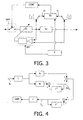
- Figure 3 is a schematic representation of receiving system according to the invention during this second mode of operation.
- the switching device is in position 2.
- the adaptive equalizer (E1) and the clock recovery device (TR) do not not operate simultaneously in the preferred embodiment.
- the system receiver according to the invention has a means (F) for freezing, during a period of given time, the operation of one of the two devices while the other device works normally.
- the operation of each devices are frozen for half the time by setting their gain to zero. This mode of operation allows to save 50% in terms of computing load.
- FIG. 4 shows in more detail the operation of the second-order phase lock of the clock recovery device.
- g 1 and g 2 are constants that define the evolution of the process.
- the constants g 1 and g 2 are empirically set so as to obtain a rapid convergence of the second order slur.
- Threshold blocks (L) make it possible to apply discontinuous corrections to ⁇ n and ⁇ and n only when they exceed a certain threshold. This threshold is chosen so as to increase the stability of the system.
- a receiver system (R) ensures independent operation the adaptive equalizer (E1) and the clock recovery device (TR), thus avoiding interference between these two devices.
- the effectiveness of the equalization is therefore improved, as is the convergence of the device allowing recover the clock rate (TR).
Landscapes
- Engineering & Computer Science (AREA)
- Power Engineering (AREA)
- Computer Networks & Wireless Communication (AREA)
- Signal Processing (AREA)
- Synchronisation In Digital Transmission Systems (AREA)
- Cable Transmission Systems, Equalization Of Radio And Reduction Of Echo (AREA)
- Dc Digital Transmission (AREA)
Description
- la figure 1 est une représentation de la réponse impulsionnelle du filtre de l'égaliseur et du décalage de la réponse impulsionnelle dû au fonctionnement simultané de l'égaliseur adaptatif et du dispositif de récupération du rythme d'horloge,
- la figure 2 est une représentation schématique illustrant le fonctionnement général d'un système récepteur selon l'invention,
- la figure 3 est une représentation schématique d'un système récepteur selon l'invention dans le second mode de fonctionnement,
- la figure 4 est une représentation schématique montrant le fonctionnement d'une boude à verrouillage de phase du second ordre.

- n est un numéro de symbole,
- k correspond au nombre de paires de symboles pris en compte dans la fenêtre d'égalisation (EW),
- Re() représente la fonction partie réelle.
- K est une constante,
- σ2 est la variance du signal.
Claims (8)
- Système récepteur (R) comprenant un premier égaliseur (E1) adaptatif associé à un premier détecteur à seuil (S1) et un dispositif permettant de récupérer le rythme d'horloge (TR) d'un système émetteur pour ledit système récepteur (R) à partir d'un signal égalisé (yn) et un signal issu du seuillage (sn) caractérisé en ce que ledit système récepteur (R) comprend également un second égaliseur (E2), qui est un égaliseur fixe, associé à un second détecteur à seuil (S2) ainsi qu'un dispositif (SW) permettant de commuter d'un premier mode de fonctionnement où le signal égalisé (yn) et le signal issu du seuillage (sn) sont destinés à être délivrés respectivement par le second égaliseur (E2) et le second détecteur à seuil (52) vers un second mode de fonctionnement où lesdits signaux (yn et sn) sont destinés à être délivrés par le premier égaliseur (E1) et le premier détecteur à seuil (S1).
- Système récepteur (R) selon la revendication 1, caractérisé en ce que le premier égaliseur (E1) est destiné à transférer, à des intervalles de temps appropriés, des coefficients d'un filtre adaptatif vers le second égaliseur (E2), lesdits coefficients étant calculés à partir d'une erreur d'égalisation, égale à une différence entre les signaux issus du premier égaliseur (E1) et du premier détecteur à seuil (S1).
- Système récepteur (R) selon la revendication 1, caractérisé en ce que le dispositif de récupération du rythme d'horloge (TR) comprend un moyen permettant d'estimer un décalage de phase entre les horloges des systèmes émetteur et récepteur en asservissant une fonction telle que :où :
 n est un numéro de symbole,k indique le nombre de paires de symboles pris en compte dans une fenêtre d'égalisation,Re() représente la fonction partie réelle.
 - Système récepteur (R) selon la revendication 1, caractérisé en ce qu'il comprend un moyen (F) permettant de faire fonctionner alternativement le dispositif de récupération du rythme d'horloge (TR) et le premier égaliseur (E1) durant le second mode de fonctionnement.
- Modem comprenant un système récepteur (R) selon l'une quelconque des revendications 1 à 4.
- Appareil récepteur décodeur de télévision comprenant un système récepteur (R) selon l'une quelconque des revendications 1 à 4.
- Téléviseur comprenant un système récepteur (R) selon l'une quelconque des revendications 1 à 4.
- Système de communication numérique comportant au moins un système émetteur et au moins un système récepteur (R), selon l'une quelconque des revendications 1 à 4, qui communiquent entre eux à travers un canal.
Applications Claiming Priority (2)
| Application Number | Priority Date | Filing Date | Title |
|---|---|---|---|
| FR9912065A FR2799074A1 (fr) | 1999-09-28 | 1999-09-28 | Dispositif de recuperation du rythme d'horloge utilisant un egaliseur fixe |
| FR9912065 | 1999-09-28 |
Publications (2)
| Publication Number | Publication Date |
|---|---|
| EP1089508A1 EP1089508A1 (fr) | 2001-04-04 |
| EP1089508B1 true EP1089508B1 (fr) | 2005-08-24 |
Family
ID=9550302
Family Applications (1)
| Application Number | Title | Priority Date | Filing Date |
|---|---|---|---|
| EP00203258A Expired - Lifetime EP1089508B1 (fr) | 1999-09-28 | 2000-09-20 | Dispositif de récupération du rythme d'horloge utilisant un égaliseur fixe |
Country Status (5)
| Country | Link |
|---|---|
| US (1) | US6831958B1 (fr) |
| EP (1) | EP1089508B1 (fr) |
| JP (1) | JP2001148642A (fr) |
| DE (1) | DE60022146T2 (fr) |
| FR (1) | FR2799074A1 (fr) |
Families Citing this family (6)
| Publication number | Priority date | Publication date | Assignee | Title |
|---|---|---|---|---|
| US7079574B2 (en) * | 2001-01-17 | 2006-07-18 | Radiant Networks Plc | Carrier phase recovery system for adaptive burst modems and link hopping radio networks |
| US20020181572A1 (en) * | 2001-06-04 | 2002-12-05 | Koninklijke Philips Electronics N.V. | Joint timing recovery and equalization for an N antenna system |
| JP3438138B2 (ja) * | 2001-06-20 | 2003-08-18 | 富士通株式会社 | 伝送路特性の周期的変動に対する等化処理方法及び装置 |
| US7092438B2 (en) * | 2002-01-22 | 2006-08-15 | Siemens Communications, Inc. | Multilevel decision feedback equalizer |
| KR20070086972A (ko) * | 2004-11-05 | 2007-08-27 | 인터디지탈 테크날러지 코포레이션 | 듀얼-모드 능동 탭 마스크 생성기 및 파일럿 기준신호 진폭제어유닛을 갖는 적응형 등화기 |
| US8284882B2 (en) * | 2009-06-25 | 2012-10-09 | Lsi Corporation | Methods and apparatus for qualification of update of clock recovery and equalization |
Family Cites Families (12)
| Publication number | Priority date | Publication date | Assignee | Title |
|---|---|---|---|---|
| FR2554996B1 (fr) * | 1983-11-14 | 1986-02-28 | Labo Electronique Physique | Procede et dispositif pour la determination de la position optimale du coefficient de reference d'un egaliseur adaptatif |
| US5420884A (en) * | 1991-04-11 | 1995-05-30 | Canon Kabushiki Kaisha | Automatic equalizer |
| US5163066A (en) * | 1991-05-24 | 1992-11-10 | At&T Bell Laboratories | Synchronizing the operation of multiple equilizers in a digital communications system |
| US5353312A (en) * | 1991-12-27 | 1994-10-04 | At&T Bell Laboratories | Equalizer-based timing recovery |
| FR2710219B1 (fr) * | 1993-09-13 | 1995-12-01 | Trt Telecom Radio Electr | Dispositif de récupération du rythme d'horloge et modem comportant un tel dispositif. |
| WO1995010888A1 (fr) * | 1993-10-12 | 1995-04-20 | Ntt Mobile Communications Network Inc. | Capteur d'etalement du temps de propagation et circuit de commutation de detection utilisant ce capteur |
| KR960010495B1 (ko) * | 1993-11-04 | 1996-08-01 | 대우전자 주식회사 | 채널 등화방법 및 장치 |
| EP0656694A3 (fr) * | 1993-11-30 | 1999-12-01 | AT&T Corp. | Egaliseur avec détection de la longueur de la ligne |
| US5872815A (en) * | 1996-02-16 | 1999-02-16 | Sarnoff Corporation | Apparatus for generating timing signals for a digital television signal receiver |
| US6307884B1 (en) * | 1998-05-29 | 2001-10-23 | Seagate Technology Llc | Dual decision feedback equalizer with selective attenuation to improve channel performance |
| US6337878B1 (en) * | 1999-03-03 | 2002-01-08 | Nxt Wave Communications | Adaptive equalizer with decision directed constant modulus algorithm |
| US6668014B1 (en) * | 1999-12-09 | 2003-12-23 | Ati Technologies Inc. | Equalizer method and apparatus using constant modulus algorithm blind equalization and partial decoding |
-
1999
- 1999-09-28 FR FR9912065A patent/FR2799074A1/fr not_active Withdrawn
-
2000
- 2000-09-20 EP EP00203258A patent/EP1089508B1/fr not_active Expired - Lifetime
- 2000-09-20 DE DE60022146T patent/DE60022146T2/de not_active Expired - Lifetime
- 2000-09-22 US US09/667,985 patent/US6831958B1/en not_active Expired - Lifetime
- 2000-09-27 JP JP2000294775A patent/JP2001148642A/ja not_active Withdrawn
Also Published As
| Publication number | Publication date |
|---|---|
| US6831958B1 (en) | 2004-12-14 |
| EP1089508A1 (fr) | 2001-04-04 |
| DE60022146D1 (de) | 2005-09-29 |
| JP2001148642A (ja) | 2001-05-29 |
| FR2799074A1 (fr) | 2001-03-30 |
| DE60022146T2 (de) | 2006-04-20 |
Similar Documents
| Publication | Publication Date | Title |
|---|---|---|
| EP0125722B1 (fr) | Circuit d'égalisation adaptative et de démodulation conjointes | |
| EP0178720B1 (fr) | Dispositif de réception de données numériques comportant un dispositif de récupération adaptative de rythme | |
| EP0547539B1 (fr) | Dispositif de récupération de rythme pour installation de réception utilisant l'égalisation auto-adaptive à suréchantillonnage associée à la démodulation différentiellement cohérente | |
| EP0146979B1 (fr) | Procédé et dispositif pour la détermination de la position optimale du coefficient de référence d'un égaliseur adaptatif | |
| FR2540314A1 (fr) | Procede d'initialisation des coefficients de filtres dans un dispositif d'annulation d'echos proche et lointain et dispositif de mise en oeuvre de ce procede | |
| EP0107246A1 (fr) | Récepteur pour modem de transmission de données, comportant un annuleur d'écho et un égaliseur | |
| EP0081437A1 (fr) | Systéme annuleur d'écho | |
| FR2837038A1 (fr) | Procede et systeme d'extraction de signal d'horloge permettant une synchronisation des horloges sur un reseau de transmission par paquets | |
| EP1089508A1 (fr) | Dispositif de récupération du rythme d'horloge utilisant un égaliseur fixe | |
| EP0039980B1 (fr) | Système adaptatif de réception de données numériques à compensation des distorsions d'amplitude etde phase introduites par le canal de transmission des données | |
| EP0275790B1 (fr) | Terminal de transmission de données sur une voie analogique bidirectionnelle avec annulation d'écho couplée au rythme réception | |
| EP1206045B1 (fr) | Procédé de correction de l'erreur de frequence | |
| FR2826810A1 (fr) | Dispositif de synchronisation et d'egalisation pour un recepteur de systeme de transmission numerique | |
| EP0494003B1 (fr) | Un système récepteur pour le traitement de signaux reçus sur des voies de diversité | |
| CA2196209C (fr) | Procede de compensation des differences en temps de propagation de groupe entre les filtres analogiques d'un emetteur et ceux d'un recepteur de signaux en quadrature de phase, dispositif de compensation et systeme de transmission correspondants | |
| FR2770355A1 (fr) | Recuperation du rythme avec un minimum de gigue | |
| EP1127305A1 (fr) | Procede et dispositif de synchronisation d'une horloge locale sur l'horloge d'un reseau de communication sans fil | |
| EP3963757B1 (fr) | Procédé et dispositif récepteur pour détecter le début d'une trame d'un signal de communications par satellite | |
| EP1556977A1 (fr) | Procede de synchronisation de donnees en sortie d'un egaliseur | |
| EP1875634A1 (fr) | Procede de synchronisation et d'asservissement dans les systemes de communications sans fil | |
| WO2021099071A1 (fr) | Procédé de traitement d'un signal mis en œuvre par un dispositif de réception d'un premier site de diffusion pour supprimer un signal interférent, dispositif de réception et programme d'ordinateur correspondants. | |
| FR2683689A1 (fr) | Procede d'egalisation frequentielle d'un canal de transmission numerique et emetteur et recepteur pour la mise en óoeuvre du procede. | |
| EP0070236B1 (fr) | Dispositif de compensation de phase d'écho et son application aux annuleurs d'écho | |
| KR100364542B1 (ko) | 심볼 동기화 장치 | |
| FR2598868A1 (fr) | Procede et dispositif de recuperation du rythme et de la phase d'un signal numerique, utilisant la derivee du signal, et systeme de reception de ce signal utilisant le dispositif |
Legal Events
| Date | Code | Title | Description |
|---|---|---|---|
| PUAI | Public reference made under article 153(3) epc to a published international application that has entered the european phase |
Free format text: ORIGINAL CODE: 0009012 |
|
| AK | Designated contracting states |
Kind code of ref document: A1 Designated state(s): DE ES FR GB IT |
|
| AX | Request for extension of the european patent |
Free format text: AL;LT;LV;MK;RO;SI |
|
| 17P | Request for examination filed |
Effective date: 20011004 |
|
| AKX | Designation fees paid |
Free format text: DE ES FR GB IT |
|
| GRAP | Despatch of communication of intention to grant a patent |
Free format text: ORIGINAL CODE: EPIDOSNIGR1 |
|
| GRAP | Despatch of communication of intention to grant a patent |
Free format text: ORIGINAL CODE: EPIDOSNIGR1 |
|
| GRAP | Despatch of communication of intention to grant a patent |
Free format text: ORIGINAL CODE: EPIDOSNIGR1 |
|
| GRAS | Grant fee paid |
Free format text: ORIGINAL CODE: EPIDOSNIGR3 |
|
| GRAA | (expected) grant |
Free format text: ORIGINAL CODE: 0009210 |
|
| AK | Designated contracting states |
Kind code of ref document: B1 Designated state(s): DE ES FR GB IT |
|
| PG25 | Lapsed in a contracting state [announced via postgrant information from national office to epo] |
Ref country code: IT Free format text: LAPSE BECAUSE OF FAILURE TO SUBMIT A TRANSLATION OF THE DESCRIPTION OR TO PAY THE FEE WITHIN THE PRE;WARNING: LAPSES OF ITALIAN PATENTS WITH EFFECTIVE DATE BEFORE 2007 MAY HAVE OCCURRED AT ANY TIME BEFORE 2007. THE CORRECT EFFECTIVE DATE MAY BE DIFFERENT FROM THE ONE RECORDED.SCRIBED TIME-LIMIT Effective date: 20050824 |
|
| REG | Reference to a national code |
Ref country code: GB Ref legal event code: FG4D Free format text: NOT ENGLISH |
|
| REF | Corresponds to: |
Ref document number: 60022146 Country of ref document: DE Date of ref document: 20050929 Kind code of ref document: P |
|
| GBT | Gb: translation of ep patent filed (gb section 77(6)(a)/1977) |
Effective date: 20051005 |
|
| PG25 | Lapsed in a contracting state [announced via postgrant information from national office to epo] |
Ref country code: ES Free format text: LAPSE BECAUSE OF FAILURE TO SUBMIT A TRANSLATION OF THE DESCRIPTION OR TO PAY THE FEE WITHIN THE PRESCRIBED TIME-LIMIT Effective date: 20051205 |
|
| PLBE | No opposition filed within time limit |
Free format text: ORIGINAL CODE: 0009261 |
|
| STAA | Information on the status of an ep patent application or granted ep patent |
Free format text: STATUS: NO OPPOSITION FILED WITHIN TIME LIMIT |
|
| 26N | No opposition filed |
Effective date: 20060526 |
|
| REG | Reference to a national code |
Ref country code: GB Ref legal event code: 732E Free format text: REGISTERED BETWEEN 20090312 AND 20090318 |
|
| PGFP | Annual fee paid to national office [announced via postgrant information from national office to epo] |
Ref country code: FR Payment date: 20080926 Year of fee payment: 9 |
|
| REG | Reference to a national code |
Ref country code: FR Ref legal event code: ST Effective date: 20110422 |
|
| PG25 | Lapsed in a contracting state [announced via postgrant information from national office to epo] |
Ref country code: FR Free format text: LAPSE BECAUSE OF NON-PAYMENT OF DUE FEES Effective date: 20090930 |
|
| REG | Reference to a national code |
Ref country code: GB Ref legal event code: 732E Free format text: REGISTERED BETWEEN 20120524 AND 20120530 |
|
| REG | Reference to a national code |
Ref country code: DE Ref legal event code: R082 Ref document number: 60022146 Country of ref document: DE Representative=s name: PATENTANWAELTE BRESSEL UND PARTNER, DE |
|
| REG | Reference to a national code |
Ref country code: DE Ref legal event code: R082 Ref document number: 60022146 Country of ref document: DE Representative=s name: PATENTANWAELTE BRESSEL UND PARTNER MBB, DE Effective date: 20120626 Ref country code: DE Ref legal event code: R081 Ref document number: 60022146 Country of ref document: DE Owner name: FUNAI ELECTRIC CO., LTD., JP Free format text: FORMER OWNER: IPG ELECTRONICS 503 LTD., ST. PETER PORT, GUERNSEY, GB Effective date: 20120626 |
|
| PGFP | Annual fee paid to national office [announced via postgrant information from national office to epo] |
Ref country code: DE Payment date: 20160913 Year of fee payment: 17 Ref country code: GB Payment date: 20160914 Year of fee payment: 17 |
|
| REG | Reference to a national code |
Ref country code: DE Ref legal event code: R119 Ref document number: 60022146 Country of ref document: DE |
|
| GBPC | Gb: european patent ceased through non-payment of renewal fee |
Effective date: 20170920 |
|
| PG25 | Lapsed in a contracting state [announced via postgrant information from national office to epo] |
Ref country code: DE Free format text: LAPSE BECAUSE OF NON-PAYMENT OF DUE FEES Effective date: 20180404 Ref country code: GB Free format text: LAPSE BECAUSE OF NON-PAYMENT OF DUE FEES Effective date: 20170920 |