EP1089508A1 - Device for clock recovery using a fixed equalizer - Google Patents
Device for clock recovery using a fixed equalizer Download PDFInfo
- Publication number
- EP1089508A1 EP1089508A1 EP00203258A EP00203258A EP1089508A1 EP 1089508 A1 EP1089508 A1 EP 1089508A1 EP 00203258 A EP00203258 A EP 00203258A EP 00203258 A EP00203258 A EP 00203258A EP 1089508 A1 EP1089508 A1 EP 1089508A1
- Authority
- EP
- European Patent Office
- Prior art keywords
- equalizer
- receiver system
- receiver
- clock
- threshold detector
- Prior art date
- Legal status (The legal status is an assumption and is not a legal conclusion. Google has not performed a legal analysis and makes no representation as to the accuracy of the status listed.)
- Granted
Links
Images

Classifications
-
- H—ELECTRICITY
- H04—ELECTRIC COMMUNICATION TECHNIQUE
- H04L—TRANSMISSION OF DIGITAL INFORMATION, e.g. TELEGRAPHIC COMMUNICATION
- H04L25/00—Baseband systems
- H04L25/02—Details ; arrangements for supplying electrical power along data transmission lines
- H04L25/03—Shaping networks in transmitter or receiver, e.g. adaptive shaping networks
- H04L25/03006—Arrangements for removing intersymbol interference
- H04L25/03012—Arrangements for removing intersymbol interference operating in the time domain
- H04L25/03019—Arrangements for removing intersymbol interference operating in the time domain adaptive, i.e. capable of adjustment during data reception
- H04L25/03038—Arrangements for removing intersymbol interference operating in the time domain adaptive, i.e. capable of adjustment during data reception with a non-recursive structure
-
- H—ELECTRICITY
- H04—ELECTRIC COMMUNICATION TECHNIQUE
- H04L—TRANSMISSION OF DIGITAL INFORMATION, e.g. TELEGRAPHIC COMMUNICATION
- H04L25/00—Baseband systems
- H04L25/02—Details ; arrangements for supplying electrical power along data transmission lines
- H04L25/03—Shaping networks in transmitter or receiver, e.g. adaptive shaping networks
- H04L25/03006—Arrangements for removing intersymbol interference
- H04L2025/03433—Arrangements for removing intersymbol interference characterised by equaliser structure
- H04L2025/03535—Variable structures
- H04L2025/03547—Switching between time domain structures
- H04L2025/03566—Switching between time domain structures between different tapped delay line structures
-
- H—ELECTRICITY
- H04—ELECTRIC COMMUNICATION TECHNIQUE
- H04L—TRANSMISSION OF DIGITAL INFORMATION, e.g. TELEGRAPHIC COMMUNICATION
- H04L7/00—Arrangements for synchronising receiver with transmitter
- H04L7/04—Speed or phase control by synchronisation signals
- H04L7/10—Arrangements for initial synchronisation
Definitions
- the present invention relates to a receiver system comprising a first equalizer associated with a first threshold detector and a device making it possible to recover the clock rate of a transmitting system for said receiving system from a signal equalized and a signal from the thresholding.
- Such a receiver system may be included in any communication system digital, such as, among other possible applications, a modem, a receiving device television decoder ('set-top-box' in English), or even a television.
- Patent application FR 93 10866 describes such a receiver system.
- the device recovery of the clock rhythm includes a phase-locked loop of the second order whose input is a function depending on the offset between the clocks of the systems transmitter and receiver.
- the output of this loop is sent to a control device which decides which advance or delay to apply to the clock of the receiving system.
- the receiver system as designed in the prior art has a certain number of drawbacks.
- the simultaneous operation of the adaptive equalizer and the recovery of the clock rhythm is a source of instability for the receiving system.
- these two devices interfere with each other, especially during the initialization phase of communication.
- the clock rhythm is not yet recovered and the adaptation of the equalizer then depends notably on the error due to the offset between the clocks of the transmitter and receiver systems.
- a offset ( ⁇ ) of the impulse response (h (t)) of the equalizer filter which is modeled here by a Nyquist function comprising a main lobe and secondary lobes, for compensate for this error.
- the impulse response of the filter being of limited length, its length being defined by an equalization window (EW), it is offset in the equalization window which amounts to shortening it.
- EW equalization window
- the object of the invention is to remedy these drawbacks to a large extent, by proposing a stable receiver system comprising an effective equalizer associated with a clock rhythm recovery device ensuring rapid clock convergence from the receiving system to that of the sending system, the receiving system allowing also to save computation time during the data transmission phase.
- the present invention provides a receiver system characterized in that that it also includes a second equalizer, which is a fixed equalizer, associated with a second threshold detector and a device for switching in a first mode where the equalized signal and the signal from the thresholding are intended to be delivered respectively by the second equalizer and the second threshold detector to a second operating mode where said signals are intended to be delivered by the first equalizer and first threshold detector.
- a second equalizer which is a fixed equalizer, associated with a second threshold detector and a device for switching in a first mode where the equalized signal and the signal from the thresholding are intended to be delivered respectively by the second equalizer and the second threshold detector to a second operating mode where said signals are intended to be delivered by the first equalizer and first threshold detector.
- Such a receiver system makes it possible to operate independently the first equalizer, i.e. the adaptive equalizer, and the rhythm recovery device clock during a first operating mode corresponding to the initialization phase of communication.
- the clock rhythm recovery device works with a second equalizer comprising a filter whose coefficients are fixed and which no longer interferes with it, thereby giving the system greater stability receiver and allowing faster convergence of the clock from the receiver system to that of the transmitting system.
- the present invention also provides a receiver system characterized in that that the first equalizer is intended to transfer, at appropriate time intervals, coefficients of an adaptive filter to the second equalizer, said coefficients being calculated at from an equalization error, equal to a difference between the signals from the first equalizer and the first threshold detector.
- the coefficients of the filter associated with the fixed equalizer are refreshed regularly further improving the convergence of the clock of the receiving system to that of the system transmitter.
- the present invention also provides a receiver system characterized in that that it includes means for alternately operating the recovery of the clock rhythm and the first equalizer during the second mode of operation.
- the clock recovery device and the first equalizer works in turn, which saves 50% of the computing load.
- Such a receiver system could finally be advantageously included in any what digital communication system.
- FIG. 2 is an illustration of the general operating principle of a system receiver (R) according to the invention.
- Such a receiving system firstly comprises a means (SAM) for sampling, at the sampling frequency of the receiving system, a demodulated signal.
- SAM means for sampling, at the sampling frequency of the receiving system, a demodulated signal.
- the receiver system then comprises first (E1) and second (E2) equalizers intended to receive the sampled signal.
- the receiver system also includes first (S1) and second (S2) threshold detectors intended to receive signals from the first (E1) and the second (E2) equalizer.
- the first equalizer (E1) is an adaptive equalizer.
- the equalizer filter is a finite impulse response digital bandpass filter called an FIR filter.
- the second equalizer (E2) is a fixed equalizer, thereby using a filter whose coefficients are fixed.
- the receiving system further comprises a device for recovering the clock rhythm (TR) of a transmitting system for the receiving system intended to receive the equalized signals (y n ) and originating from the thresholding (s n ) coming respectively from 'an equalizer and the associated threshold detector.
- TR clock rhythm
- the recovery of the clock rhythm is carried out using a second-order phase-locked loop whose input is an estimate of the phase error calculated from the equalization error e n .
- the output of the phase locked loop is sent to a receiver system clock controller (CONT) which allows the sampling signal to be advanced or delayed (SAM).
- CONT receiver system clock controller
- the receiving system finally comprises a device (SW) making it possible to switch from a first operating mode (position 1) where the device for recovering the clock rhythm (TR) receives the signals (y n and s n ) coming from the second equalizer (E2) and from the second threshold detector (S2) to a second operating mode (position 2) where the clock rhythm recovery device (TR) receives the signals (y n and s n ) from the first equalizer (E1) and the first threshold detector (S1).
- a device (SW) making it possible to switch from a first operating mode (position 1) where the device for recovering the clock rhythm (TR) receives the signals (y n and s n ) coming from the second equalizer (E2) and from the second threshold detector (S2) to a second operating mode (position 2) where the clock rhythm recovery device (TR) receives the signals (y n and s n ) from the first equalizer (E1) and the first threshold detector (S1).
- the first mode of operation corresponds during the initialization phase of the communication. It thus appears that during this phase, the adaptive equalizer (E1) and the clock rhythm recovery device (TR) work independently of each other, the clock rhythm recovery device receiving in this case the signals from the fixed equalizer (E2) and the second threshold detector (S2).
- the adaptation device (AD) associated with the adaptive equalizer calculates the coefficients of the adaptive filter which are transferred (T), at appropriate time intervals, from the adaptive equalizer (E1) to the fixed equalizer (E2). Two to three transfers of coefficients are carried out in the embodiment prefer.
- the coefficients of the fixed equalizer filter (E2) are first initialized to 0. The first transfer then occurs after processing of a reference sequence comprising a determined number of symbols (512 in the preferred embodiment), to allow rough convergence of the phase locked loop. Then the subsequent transfers are performed based on the value of a signal to noise ratio calculated at the output of the fixed equalizer (E2) and ensure finer convergence of the process.
- Such a cooling of the coefficients of the filter of the fixed equalizer (E2) allows improve the convergence of the clock rhythm recovery device.
- the second mode of operation corresponds during the data transmission phase.
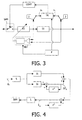
- Figure 3 is a schematic representation of the receiver system according to the invention during this second operating mode.
- the switching device is in position 2.
- the adaptive equalizer (E1) and the clock rhythm recovery device (TR) do not not operate simultaneously in the preferred embodiment.
- the system receiver according to the invention has a means (F) for freezing, for a period of given time, the operation of one of the two devices while the other device works normally.
- the operation of each of devices is frozen for half the time by setting its gain to zero. This mode of operation thus saves 50% in terms of computational load.
- Figure 4 shows in more detail how the loop works. second order phase locking of the clock rhythm recovery device.
- g 1 and g 2 are constants that define the evolution of the process.
- the constants g 1 and g 2 are fixed empirically so as to obtain rapid convergence of the second order loop.
- Threshold blocks (L) make it possible to apply discontinuous corrections to ⁇ n and ⁇ ⁇ n , only when they exceed a certain threshold. This threshold is chosen so as to increase the stability of the system.
- a receiver system (R) ensures independent operation the adaptive equalizer (E1) and the clock rhythm recovery device (TR), thus avoiding interference between these two devices.
- the effectiveness of equalization is therefore improved, as is the convergence of the device making it possible to recover the clock rate (TR).
Landscapes
- Engineering & Computer Science (AREA)
- Power Engineering (AREA)
- Computer Networks & Wireless Communication (AREA)
- Signal Processing (AREA)
- Cable Transmission Systems, Equalization Of Radio And Reduction Of Echo (AREA)
- Synchronisation In Digital Transmission Systems (AREA)
- Dc Digital Transmission (AREA)
Abstract
Description
La présente invention concerne un système récepteur comprenant un premier égaliseur associé à un premier détecteur à seuil et un dispositif permettant de récupérer le rythme d'horloge d'un système émetteur pour ledit système récepteur à partir d'un signal égalisé et d'un signal issu du seuillage.The present invention relates to a receiver system comprising a first equalizer associated with a first threshold detector and a device making it possible to recover the clock rate of a transmitting system for said receiving system from a signal equalized and a signal from the thresholding.
Un tel système récepteur pourra être inclus dans tout système de communication numérique, comme, entre autres applications possibles, un modem, un appareil récepteur décodeur de télévision ('set-top-box' en anglais), ou encore un téléviseur.Such a receiver system may be included in any communication system digital, such as, among other possible applications, a modem, a receiving device television decoder ('set-top-box' in English), or even a television.
La demande de brevet FR 93 10866 décrit un tel système récepteur. Le dispositif de récupération du rythme d'horloge comporte une boucle à verrouillage de phase du second ordre dont l'entrée est une fonction dépendant du décalage entre les horloges des systèmes émetteur et récepteur. La sortie de cette boucle est envoyée à un dispositif de contrôle qui décide de l'avance ou du retard à appliquer à l'horloge du système récepteur.Patent application FR 93 10866 describes such a receiver system. The device recovery of the clock rhythm includes a phase-locked loop of the second order whose input is a function depending on the offset between the clocks of the systems transmitter and receiver. The output of this loop is sent to a control device which decides which advance or delay to apply to the clock of the receiving system.
Le système récepteur tel qu'il est conçu dans l'art antérieur présente un certain nombre d'inconvénients.The receiver system as designed in the prior art has a certain number of drawbacks.
Tout d'abord, le fonctionnement simultané de l'égaliseur adaptatif et du dispositif de récupération du rythme d'horloge est une source d'instabilité pour le système récepteur. En effet, ces deux dispositifs interfèrent entre eux, notamment lors de la phase d'initialisation de la communication. Durant cette période, le rythme d'horloge n'est pas encore récupéré et l'adaptation de l'égaliseur dépend alors notablement de l'erreur due au décalage entre les horloges des systèmes émetteur et récepteur. Il en résulte, comme l'illustre la figure 1, un décalage (δ) de la réponse impulsionnelle (h(t)) du filtre de l'égaliseur, qui est ici modélisée par une fonction de Nyquist comportant un lobe principal et des lobes secondaires, pour compenser cette erreur. La réponse impulsionnelle du filtre étant de longueur limitée, sa longueur étant définie par une fenêtre d'égalisation (EW), elle se trouve décentrée dans la fenêtre d'égalisation ce qui revient à la raccourcir. Le canal est ainsi mal égalisé et la convergence du dispositif de récupération du rythme d'horloge se trouve ralentie.First, the simultaneous operation of the adaptive equalizer and the recovery of the clock rhythm is a source of instability for the receiving system. In indeed, these two devices interfere with each other, especially during the initialization phase of communication. During this period, the clock rhythm is not yet recovered and the adaptation of the equalizer then depends notably on the error due to the offset between the clocks of the transmitter and receiver systems. As a result, as illustrated in FIG. 1, a offset (δ) of the impulse response (h (t)) of the equalizer filter, which is modeled here by a Nyquist function comprising a main lobe and secondary lobes, for compensate for this error. The impulse response of the filter being of limited length, its length being defined by an equalization window (EW), it is offset in the equalization window which amounts to shortening it. The channel is thus poorly equalized and the convergence of the clock rhythm recovery device is slowed down.
De plus, les opérations réalisées par l'égaliseur adaptatif et par le dispositif de récupération du rythme d'horloge sont coûteuses en terme de temps de calcul, notamment durant la phase de transmission de données. In addition, the operations performed by the adaptive equalizer and by the recovery of the clock rhythm are costly in terms of computation time, in particular during the data transmission phase.
L'invention a pour but de remédier dans une large mesure à ces inconvénients, en proposant un système récepteur stable comprenant un égaliseur efficace associé à un dispositif de récupération du rythme d'horloge assurant une convergence rapide de l'horloge du système récepteur vers celle du système émetteur, le système récepteur permettant également d'économiser du temps de calcul lors de la phase de transmission des données.The object of the invention is to remedy these drawbacks to a large extent, by proposing a stable receiver system comprising an effective equalizer associated with a clock rhythm recovery device ensuring rapid clock convergence from the receiving system to that of the sending system, the receiving system allowing also to save computation time during the data transmission phase.
A cet effet, la présente invention propose un système récepteur caractérisé en ce qu'il comprend également un second égaliseur, qui est un égaliseur fixe, associé à un second détecteur à seuil ainsi qu'un dispositif permettant de commuter d'un premier mode de fonctionnement où le signal égalisé et le signal issu du seuillage sont destinés à être délivrés respectivement par le second égaliseur et le second détecteur à seuil vers un second mode de fonctionnement où lesdits signaux sont destinés à être délivrés par le premier égaliseur et le premier détecteur à seuil.To this end, the present invention provides a receiver system characterized in that that it also includes a second equalizer, which is a fixed equalizer, associated with a second threshold detector and a device for switching in a first mode where the equalized signal and the signal from the thresholding are intended to be delivered respectively by the second equalizer and the second threshold detector to a second operating mode where said signals are intended to be delivered by the first equalizer and first threshold detector.
Un tel système récepteur permet de faire fonctionner indépendamment le premier égaliseur, c'est à dire l'égaliseur adaptatif, et le dispositif de récupération du rythme d'horloge lors d'un premier mode de fonctionnement correspondant à la phase d'initialisation de la communication. Durant cette période, le dispositif de récupération du rythme d'horloge fonctionne avec un second égaliseur comportant un filtre dont les coefficients sont fixes et qui n'interfère plus de ce fait avec lui, conférant ainsi une plus grande stabilité au système récepteur et permettant une convergence plus rapide de l'horloge du système récepteur vers celle du système émetteur.Such a receiver system makes it possible to operate independently the first equalizer, i.e. the adaptive equalizer, and the rhythm recovery device clock during a first operating mode corresponding to the initialization phase of communication. During this period, the clock rhythm recovery device works with a second equalizer comprising a filter whose coefficients are fixed and which no longer interferes with it, thereby giving the system greater stability receiver and allowing faster convergence of the clock from the receiver system to that of the transmitting system.
La présente invention propose également un système récepteur caractérisé en ce que le premier égaliseur est destiné à transférer, à des intervalles de temps appropriés, des coefficients d'un filtre adaptatif vers le second égaliseur, lesdits coefficients étant calculés à partir d'une erreur d'égalisation, égale à une différence entre les signaux issus du premier égaliseur et du premier détecteur à seuil.The present invention also provides a receiver system characterized in that that the first equalizer is intended to transfer, at appropriate time intervals, coefficients of an adaptive filter to the second equalizer, said coefficients being calculated at from an equalization error, equal to a difference between the signals from the first equalizer and the first threshold detector.
Ainsi, les coefficients du filtre associé à l'égaliseur fixe sont rafraíchis régulièrement améliorant encore la convergence de l'horloge du système récepteur vers celle du système émetteur.Thus, the coefficients of the filter associated with the fixed equalizer are refreshed regularly further improving the convergence of the clock of the receiving system to that of the system transmitter.
La présente invention propose également un système récepteur caractérisé en ce qu'il comprend un moyen permettant de faire fonctionner alternativement le dispositif de récupération du rythme d'horloge et le premier égaliseur durant le second mode de fonctionnement.The present invention also provides a receiver system characterized in that that it includes means for alternately operating the recovery of the clock rhythm and the first equalizer during the second mode of operation.
Ainsi, dans le second mode de fonctionnement, correspondant à la phase de transmission de données, le dispositif de récupération du rythme d'horloge et le premier égaliseur fonctionne à tour de rôle, ce qui permet d'économiser 50% de la charge de calcul.Thus, in the second operating mode, corresponding to the phase of data transmission, the clock recovery device and the first equalizer works in turn, which saves 50% of the computing load.
Un tel système récepteur pourra enfin être avantageusement inclus dans n'importe quel système de communication numérique. Such a receiver system could finally be advantageously included in any what digital communication system.
Ces aspects de l'invention ainsi que d'autres aspects plus détaillés apparaítront plus clairement grâce à la description suivante de plusieurs modes de réalisation de l'invention, donnés à titre d'exemples non limitatifs et en regard des dessins annexés dans lesquels:
- la figure 1 est une représentation de la réponse impulsionnelle du filtre de l'égaliseur et du décalage de la réponse impulsionnelle dû au fonctionnement simultané de l'égaliseur adaptatif et du dispositif de récupération du rythme d'horloge,
- la figure 2 est une représentation schématique illustrant le fonctionnement général d'un système récepteur selon l'invention,
- la figure 3 est une représentation schématique d'un système récepteur selon l'invention dans le second mode de fonctionnement,
- la figure 4 est une représentation schématique montrant le fonctionnement d'une boucle à verrouillage de phase du second ordre.
- FIG. 1 is a representation of the impulse response of the equalizer filter and of the offset of the impulse response due to the simultaneous operation of the adaptive equalizer and the device for recovering the clock rate,
- FIG. 2 is a schematic representation illustrating the general operation of a receiver system according to the invention,
- FIG. 3 is a schematic representation of a receiver system according to the invention in the second mode of operation,
- Figure 4 is a schematic representation showing the operation of a second order phase locked loop.
La figure 2 est une illustration du principe de fonctionnement général d'un système récepteur (R) selon l'invention.Figure 2 is an illustration of the general operating principle of a system receiver (R) according to the invention.
Un tel système récepteur comprend tout d'abord un moyen (SAM) pour échantillonner, à la fréquence d'échantillonnage du système récepteur, un signal démodulé.Such a receiving system firstly comprises a means (SAM) for sampling, at the sampling frequency of the receiving system, a demodulated signal.
Le système récepteur comprend ensuite des premier (E1) et second (E2) égaliseurs destinés à recevoir le signal échantillonné.The receiver system then comprises first (E1) and second (E2) equalizers intended to receive the sampled signal.
Le système récepteur comprend également des premier (S1) et second (S2) détecteurs à seuil destinés à recevoir respectivement des signaux issus du premier (E1) et du second (E2) égaliseur.The receiver system also includes first (S1) and second (S2) threshold detectors intended to receive signals from the first (E1) and the second (E2) equalizer.
Le premier égaliseur (E1) est un égaliseur adaptatif. Dans le mode de réalisation
préféré, le filtre de l'égaliseur est un filtre numérique passe-bande à réponse impulsionnelle
finie appelé filtre FIR. L'égalisation est dans ce cas réalisée en utilisant un dispositif
d'adaptation (AD) qui calcule les coefficients du filtre numérique FIR en fonction de l'erreur
d'égalisation en définie par:
Le système récepteur comprend, en outre, un dispositif de récupération du rythme d'horloge (TR) d'un système émetteur pour le système récepteur destiné à recevoir les signaux égalisé (yn) et issu du seuillage (sn) provenant respectivement d'un égaliseur et du détecteur à seuil qui lui est associé. The receiving system further comprises a device for recovering the clock rhythm (TR) of a transmitting system for the receiving system intended to receive the equalized signals (y n ) and originating from the thresholding (s n ) coming respectively from 'an equalizer and the associated threshold detector.
La récupération du rythme d'horloge est réalisée à l'aide d'une boucle à verrouillage de phase du second ordre dont l'entrée est une estimation de l'erreur de phase calculée à partir de l'erreur d'égalisation en. La sortie de la boucle à verrouillage de phase est envoyée à un dispositif de contrôle de l'horloge du système récepteur (CONT) qui permet d'avancer ou de retarder l'échantillonnage (SAM) du signal reçu.The recovery of the clock rhythm is carried out using a second-order phase-locked loop whose input is an estimate of the phase error calculated from the equalization error e n . The output of the phase locked loop is sent to a receiver system clock controller (CONT) which allows the sampling signal to be advanced or delayed (SAM).
Le système récepteur comprend enfin un dispositif (SW) permettant de commuter d'un premier mode de fonctionnement (position 1) où le dispositif de récupération du rythme d'horloge (TR) reçoit les signaux (yn et sn) provenant du second égaliseur (E2) et du second détecteur à seuil (S2) vers un second mode de fonctionnement (position 2) où le dispositif de récupération du rythme d'horloge (TR) reçoit les signaux (yn et sn) provenant du premier égaliseur (E1) et du premier détecteur à seuil (S1).The receiving system finally comprises a device (SW) making it possible to switch from a first operating mode (position 1) where the device for recovering the clock rhythm (TR) receives the signals (y n and s n ) coming from the second equalizer (E2) and from the second threshold detector (S2) to a second operating mode (position 2) where the clock rhythm recovery device (TR) receives the signals (y n and s n ) from the first equalizer (E1) and the first threshold detector (S1).
Dans le mode de réalisation préféré, le premier mode de fonctionnement correspond à la phase d'initialisation de la communication. Il apparaít ainsi que lors de cette phase, l'égaliseur adaptatif (E1) et le dispositif de récupération du rythme d'horloge (TR) travaille indépendamment l'un de l'autre, le dispositif de récupération du rythme d'horloge recevant dans ce cas les signaux issus de l'égaliseur fixe (E2) et du second détecteur à seuil (S2).In the preferred embodiment, the first mode of operation corresponds during the initialization phase of the communication. It thus appears that during this phase, the adaptive equalizer (E1) and the clock rhythm recovery device (TR) work independently of each other, the clock rhythm recovery device receiving in this case the signals from the fixed equalizer (E2) and the second threshold detector (S2).
Durant la phase d'initialisation de la communication, le dispositif d'adaptation (AD) associé à l'égaliseur adaptatif calcule les coefficients du filtre adaptatif qui sont transférés (T), à des intervalles de temps appropriés, de l'égaliseur adaptatif (E1) vers l'égaliseur fixe (E2). Deux à trois transferts de coefficients sont effectués dans le mode de réalisation préféré. Les coefficients du filtre de l'égaliseur fixe (E2) sont tout d'abord initialisés à 0. Le premier transfert intervient ensuite après traitement d'un séquence de référence comprenant un nombre déterminé de symboles (512 dans le mode de réalisation préféré), afin de permettre une convergence grossière de la boucle à verrouillage de phase. Puis les transferts suivants sont effectués en fonction de la valeur d'un rapport signal sur bruit calculé à la sortie de l'égaliseur fixe (E2) et assurent une convergence plus fine du processus. Un tel rafraíchissement des coefficients du filtre de l'égaliseur fixe (E2) permet d'améliorer la convergence du dispositif de récupération du rythme d'horloge.During the initialization phase of the communication, the adaptation device (AD) associated with the adaptive equalizer calculates the coefficients of the adaptive filter which are transferred (T), at appropriate time intervals, from the adaptive equalizer (E1) to the fixed equalizer (E2). Two to three transfers of coefficients are carried out in the embodiment prefer. The coefficients of the fixed equalizer filter (E2) are first initialized to 0. The first transfer then occurs after processing of a reference sequence comprising a determined number of symbols (512 in the preferred embodiment), to allow rough convergence of the phase locked loop. Then the subsequent transfers are performed based on the value of a signal to noise ratio calculated at the output of the fixed equalizer (E2) and ensure finer convergence of the process. Such a cooling of the coefficients of the filter of the fixed equalizer (E2) allows improve the convergence of the clock rhythm recovery device.
Dans le mode de réalisation préféré, le second mode de fonctionnement correspond à la phase de transmission des données. La figure 3 est une représentation schématique du système récepteur selon l'invention lors de ce second mode de fonctionnement.In the preferred embodiment, the second mode of operation corresponds during the data transmission phase. Figure 3 is a schematic representation of the receiver system according to the invention during this second operating mode.
Durant cette phase, le dispositif de commutation se trouve en position 2. Cependant,
l'égaliseur adaptatif (E1) et le dispositif de récupération du rythme d'horloge (TR) ne
fonctionnent pas simultanément dans le mode de réalisation préféré. Pour cela, le système
récepteur selon l'invention dispose d'un moyen (F) permettant de geler, pendant un laps de
temps donné, le fonctionnement de l'un des deux dispositifs tandis que l'autre dispositif
fonctionne normalement. Dans le mode de réalisation préféré, le fonctionnement de chacun
des dispositifs est figé pendant la moitié du temps en réglant son gain à zéro. Ce mode de
fonctionnement permet ainsi de gagner 50% en terme de charge de calcul.During this phase, the switching device is in
La figure 4 montre de façon plus détaillée le fonctionnement de la boucle à verrouillage de phase du second ordre du dispositif de récupération du rythme d'horloge.Figure 4 shows in more detail how the loop works. second order phase locking of the clock rhythm recovery device.
Dans le mode de réalisation préféré, le décalage de phase τ entre le système
émetteur et le système récepteur est estimé à partir d'une fonction coût qui est définie,
dans le mode de réalisation préféré, comme suit

- n est un numéro de symbole,
- k correspond au nombre de paires de symboles pris en compte dans la fenêtre d'égalisation (EW),
- Re() représente la fonction partie réelle.
- n is a symbol number,
- k corresponds to the number of pairs of symbols taken into account in the equalization window (EW),
- Re () represents the real part function.
Les symboles transmis étant statistiquement indépendants, on montre que
l'espérance E de n s'écrit:
- K est une constante,
- σ2 est la variance du signal.
- K is a constant,
- σ 2 is the variance of the signal.
L'estimation du décalage de phase τ ∧n est alors établie selon le processus défini cidessous
:
Ces équations correspondent à une boucle du second ordre et se mettent sous la forme du graphe représenté figure 4 où z-1 représente un retard de un symbole.These equations correspond to a second order loop and take the form of the graph shown in Figure 4 where z -1 represents a delay of one symbol.
La fonction de transfert équivalente de cette boucle du second ordre s'écrit alors
dans le domaine de Laplace :
On obtient ainsi l'expression de la fréquence d'oscillation ω0 et du coefficient
d'amortissement ξ de la boucle du second ordre:
Les constantes g1 et g2 sont fixées empiriquement de façon à obtenir une convergence rapide de la boucle du second ordre.The constants g 1 and g 2 are fixed empirically so as to obtain rapid convergence of the second order loop.
Des blocs de seuillage (L) permettent d'appliquer à n et τ ∧n des corrections discontinues, uniquement lorsqu'elles dépassent un certain seuil. Ce seuil est choisi de manière à augmenter la stabilité du système.Threshold blocks (L) make it possible to apply discontinuous corrections to n and τ ∧ n , only when they exceed a certain threshold. This threshold is chosen so as to increase the stability of the system.
Un système récepteur (R) selon l'invention assure un fonctionnement indépendant de l'égaliseur adaptatif (E1) et du dispositif de récupération du rythme d'horloge (TR), évitant ainsi des interférences entre ces deux dispositifs. L'efficacité de l'égalisation se trouve par conséquent améliorée, de même que la convergence du dispositif permettant de récupérer le rythme d'horloge (TR).A receiver system (R) according to the invention ensures independent operation the adaptive equalizer (E1) and the clock rhythm recovery device (TR), thus avoiding interference between these two devices. The effectiveness of equalization is is therefore improved, as is the convergence of the device making it possible to recover the clock rate (TR).
Claims (8)

Applications Claiming Priority (2)
| Application Number | Priority Date | Filing Date | Title |
|---|---|---|---|
| FR9912065 | 1999-09-28 | ||
| FR9912065A FR2799074A1 (en) | 1999-09-28 | 1999-09-28 | CLOCK RHYTHM RECOVERY DEVICE USING A FIXED EQUALIZER |
Publications (2)
| Publication Number | Publication Date |
|---|---|
| EP1089508A1 true EP1089508A1 (en) | 2001-04-04 |
| EP1089508B1 EP1089508B1 (en) | 2005-08-24 |
Family
ID=9550302
Family Applications (1)
| Application Number | Title | Priority Date | Filing Date |
|---|---|---|---|
| EP00203258A Expired - Lifetime EP1089508B1 (en) | 1999-09-28 | 2000-09-20 | Device for clock recovery using a fixed equalizer |
Country Status (5)
| Country | Link |
|---|---|
| US (1) | US6831958B1 (en) |
| EP (1) | EP1089508B1 (en) |
| JP (1) | JP2001148642A (en) |
| DE (1) | DE60022146T2 (en) |
| FR (1) | FR2799074A1 (en) |
Families Citing this family (6)
| Publication number | Priority date | Publication date | Assignee | Title |
|---|---|---|---|---|
| US7079574B2 (en) * | 2001-01-17 | 2006-07-18 | Radiant Networks Plc | Carrier phase recovery system for adaptive burst modems and link hopping radio networks |
| US20020181572A1 (en) * | 2001-06-04 | 2002-12-05 | Koninklijke Philips Electronics N.V. | Joint timing recovery and equalization for an N antenna system |
| JP3438138B2 (en) * | 2001-06-20 | 2003-08-18 | 富士通株式会社 | Equalization processing method and apparatus for periodic fluctuation of transmission line characteristics |
| US7092438B2 (en) * | 2002-01-22 | 2006-08-15 | Siemens Communications, Inc. | Multilevel decision feedback equalizer |
| US7570690B2 (en) * | 2004-11-05 | 2009-08-04 | Interdigital Technology Corporation | Adaptive equalizer with a dual-mode active taps mask generator and a pilot reference signal amplitude control unit |
| US8284882B2 (en) * | 2009-06-25 | 2012-10-09 | Lsi Corporation | Methods and apparatus for qualification of update of clock recovery and equalization |
Citations (4)
| Publication number | Priority date | Publication date | Assignee | Title |
|---|---|---|---|---|
| US4633482A (en) * | 1983-11-14 | 1986-12-30 | U. S. Philips Corporation | Method of and arrangement for determining the optimum position of the reference tap of an adaptive equalizer |
| FR2710219A1 (en) * | 1993-09-13 | 1995-03-24 | Trt Telecom Radio Electr | Clock rate recovery device and modem including such a device |
| US5420884A (en) * | 1991-04-11 | 1995-05-30 | Canon Kabushiki Kaisha | Automatic equalizer |
| US5502506A (en) * | 1993-11-04 | 1996-03-26 | Daewoo Electronics Co., Ltd. | Apparatus for equalizing television signals with fast convergence |
Family Cites Families (8)
| Publication number | Priority date | Publication date | Assignee | Title |
|---|---|---|---|---|
| US5163066A (en) * | 1991-05-24 | 1992-11-10 | At&T Bell Laboratories | Synchronizing the operation of multiple equilizers in a digital communications system |
| US5353312A (en) * | 1991-12-27 | 1994-10-04 | At&T Bell Laboratories | Equalizer-based timing recovery |
| WO1995010888A1 (en) * | 1993-10-12 | 1995-04-20 | Ntt Mobile Communications Network Inc. | Delay spread sensor and detection switching circuit using it |
| EP0656694A3 (en) * | 1993-11-30 | 1999-12-01 | AT&T Corp. | Equalizer with line length detection |
| US5872815A (en) * | 1996-02-16 | 1999-02-16 | Sarnoff Corporation | Apparatus for generating timing signals for a digital television signal receiver |
| US6307884B1 (en) * | 1998-05-29 | 2001-10-23 | Seagate Technology Llc | Dual decision feedback equalizer with selective attenuation to improve channel performance |
| US6337878B1 (en) * | 1999-03-03 | 2002-01-08 | Nxt Wave Communications | Adaptive equalizer with decision directed constant modulus algorithm |
| US6668014B1 (en) * | 1999-12-09 | 2003-12-23 | Ati Technologies Inc. | Equalizer method and apparatus using constant modulus algorithm blind equalization and partial decoding |
-
1999
- 1999-09-28 FR FR9912065A patent/FR2799074A1/en not_active Withdrawn
-
2000
- 2000-09-20 DE DE60022146T patent/DE60022146T2/en not_active Expired - Lifetime
- 2000-09-20 EP EP00203258A patent/EP1089508B1/en not_active Expired - Lifetime
- 2000-09-22 US US09/667,985 patent/US6831958B1/en not_active Expired - Lifetime
- 2000-09-27 JP JP2000294775A patent/JP2001148642A/en not_active Withdrawn
Patent Citations (4)
| Publication number | Priority date | Publication date | Assignee | Title |
|---|---|---|---|---|
| US4633482A (en) * | 1983-11-14 | 1986-12-30 | U. S. Philips Corporation | Method of and arrangement for determining the optimum position of the reference tap of an adaptive equalizer |
| US5420884A (en) * | 1991-04-11 | 1995-05-30 | Canon Kabushiki Kaisha | Automatic equalizer |
| FR2710219A1 (en) * | 1993-09-13 | 1995-03-24 | Trt Telecom Radio Electr | Clock rate recovery device and modem including such a device |
| US5502506A (en) * | 1993-11-04 | 1996-03-26 | Daewoo Electronics Co., Ltd. | Apparatus for equalizing television signals with fast convergence |
Also Published As
| Publication number | Publication date |
|---|---|
| FR2799074A1 (en) | 2001-03-30 |
| DE60022146T2 (en) | 2006-04-20 |
| EP1089508B1 (en) | 2005-08-24 |
| DE60022146D1 (en) | 2005-09-29 |
| JP2001148642A (en) | 2001-05-29 |
| US6831958B1 (en) | 2004-12-14 |
Similar Documents
| Publication | Publication Date | Title |
|---|---|---|
| EP0178720B1 (en) | Circuit arrangement for the reception of digital data with an adaptive clock recovery circuit | |
| CN109314572B (en) | Transmission characteristic compensation device, transmission characteristic compensation method, and communication device | |
| EP0547539A1 (en) | Clock recovery circuit for a receiving unit with auto-adaptive equalisation using oversampling together with differentially coherent demodulation | |
| EP0146979B1 (en) | Method and system for determining the optimum position of the reference coefficient of an adaptive equalizer | |
| EP0125722A1 (en) | Circuit for joint adaptive equalisation and demodulation | |
| EP0106406A1 (en) | Self-adaptive equalizer for base band data signal | |
| US10090870B1 (en) | Signal detection and power measurement with multi-band filter to mitigate narrowband interference | |
| EP1089508B1 (en) | Device for clock recovery using a fixed equalizer | |
| CA2006829C (en) | Self-adaptive equalizer circuit for a differentially coherent demodulation installation | |
| EP0599722B1 (en) | Apparatus for band clock recovery in a modem receiver | |
| EP0589767B1 (en) | Method for determining the transmittance of a filter circuit for transforming a filter impulse response in a minimum phase response and filter circuit using this method | |
| FR2786965A1 (en) | SIGNAL CARRIER RECOVERY METHOD | |
| FR2826810A1 (en) | SYNCHRONIZATION AND EQUALIZATION DEVICE FOR A DIGITAL TRANSMISSION SYSTEM RECEIVER | |
| EP0494003B1 (en) | Receiver for processing signals which are received over diversity paths | |
| EP0275790A1 (en) | Terminal for data transmission over an analogous bidirectional line with echo cancellation coupled to the reception clock | |
| EP1206045B1 (en) | Method of correcting frequency error | |
| FR2770355A1 (en) | RECOVERY OF THE RHYTHM WITH A MINIMUM OF JIT | |
| CA2196209C (en) | Process of compensating for the differences travel times of group between the analog filters of a transmitter and those of a receiver of signals in quadrature phase, device and system for adaptive transmission | |
| EP0682420A1 (en) | Apparatus for estimating the transmission channel quality in a digital receiver | |
| EP3963757B1 (en) | Method and receiver device for detecting the start of a frame of a satellite communications signal | |
| WO2004040814A1 (en) | Method for synchronizing an equalizer output data | |
| FR2683689A1 (en) | Method of frequency-based equalisation of a digital transmission channel, and transmitter and receiver for implementing the method | |
| WO2003036893A1 (en) | Inter-symbol interference canceller | |
| FR2598868A1 (en) | Method and device for recovering the timing and phase of a digital signal, using the derivative of the signal, and system for receiving this signal using the device | |
| FR2710211A1 (en) | Line break detection device and modem comprising such a device. |
Legal Events
| Date | Code | Title | Description |
|---|---|---|---|
| PUAI | Public reference made under article 153(3) epc to a published international application that has entered the european phase |
Free format text: ORIGINAL CODE: 0009012 |
|
| AK | Designated contracting states |
Kind code of ref document: A1 Designated state(s): DE ES FR GB IT |
|
| AX | Request for extension of the european patent |
Free format text: AL;LT;LV;MK;RO;SI |
|
| 17P | Request for examination filed |
Effective date: 20011004 |
|
| AKX | Designation fees paid |
Free format text: DE ES FR GB IT |
|
| GRAP | Despatch of communication of intention to grant a patent |
Free format text: ORIGINAL CODE: EPIDOSNIGR1 |
|
| GRAP | Despatch of communication of intention to grant a patent |
Free format text: ORIGINAL CODE: EPIDOSNIGR1 |
|
| GRAP | Despatch of communication of intention to grant a patent |
Free format text: ORIGINAL CODE: EPIDOSNIGR1 |
|
| GRAS | Grant fee paid |
Free format text: ORIGINAL CODE: EPIDOSNIGR3 |
|
| GRAA | (expected) grant |
Free format text: ORIGINAL CODE: 0009210 |
|
| AK | Designated contracting states |
Kind code of ref document: B1 Designated state(s): DE ES FR GB IT |
|
| PG25 | Lapsed in a contracting state [announced via postgrant information from national office to epo] |
Ref country code: IT Free format text: LAPSE BECAUSE OF FAILURE TO SUBMIT A TRANSLATION OF THE DESCRIPTION OR TO PAY THE FEE WITHIN THE PRE;WARNING: LAPSES OF ITALIAN PATENTS WITH EFFECTIVE DATE BEFORE 2007 MAY HAVE OCCURRED AT ANY TIME BEFORE 2007. THE CORRECT EFFECTIVE DATE MAY BE DIFFERENT FROM THE ONE RECORDED.SCRIBED TIME-LIMIT Effective date: 20050824 |
|
| REG | Reference to a national code |
Ref country code: GB Ref legal event code: FG4D Free format text: NOT ENGLISH |
|
| REF | Corresponds to: |
Ref document number: 60022146 Country of ref document: DE Date of ref document: 20050929 Kind code of ref document: P |
|
| GBT | Gb: translation of ep patent filed (gb section 77(6)(a)/1977) |
Effective date: 20051005 |
|
| PG25 | Lapsed in a contracting state [announced via postgrant information from national office to epo] |
Ref country code: ES Free format text: LAPSE BECAUSE OF FAILURE TO SUBMIT A TRANSLATION OF THE DESCRIPTION OR TO PAY THE FEE WITHIN THE PRESCRIBED TIME-LIMIT Effective date: 20051205 |
|
| PLBE | No opposition filed within time limit |
Free format text: ORIGINAL CODE: 0009261 |
|
| STAA | Information on the status of an ep patent application or granted ep patent |
Free format text: STATUS: NO OPPOSITION FILED WITHIN TIME LIMIT |
|
| 26N | No opposition filed |
Effective date: 20060526 |
|
| REG | Reference to a national code |
Ref country code: GB Ref legal event code: 732E Free format text: REGISTERED BETWEEN 20090312 AND 20090318 |
|
| PGFP | Annual fee paid to national office [announced via postgrant information from national office to epo] |
Ref country code: FR Payment date: 20080926 Year of fee payment: 9 |
|
| REG | Reference to a national code |
Ref country code: FR Ref legal event code: ST Effective date: 20110422 |
|
| PG25 | Lapsed in a contracting state [announced via postgrant information from national office to epo] |
Ref country code: FR Free format text: LAPSE BECAUSE OF NON-PAYMENT OF DUE FEES Effective date: 20090930 |
|
| REG | Reference to a national code |
Ref country code: GB Ref legal event code: 732E Free format text: REGISTERED BETWEEN 20120524 AND 20120530 |
|
| REG | Reference to a national code |
Ref country code: DE Ref legal event code: R082 Ref document number: 60022146 Country of ref document: DE Representative=s name: PATENTANWAELTE BRESSEL UND PARTNER, DE |
|
| REG | Reference to a national code |
Ref country code: DE Ref legal event code: R082 Ref document number: 60022146 Country of ref document: DE Representative=s name: PATENTANWAELTE BRESSEL UND PARTNER MBB, DE Effective date: 20120626 Ref country code: DE Ref legal event code: R081 Ref document number: 60022146 Country of ref document: DE Owner name: FUNAI ELECTRIC CO., LTD., JP Free format text: FORMER OWNER: IPG ELECTRONICS 503 LTD., ST. PETER PORT, GUERNSEY, GB Effective date: 20120626 |
|
| PGFP | Annual fee paid to national office [announced via postgrant information from national office to epo] |
Ref country code: DE Payment date: 20160913 Year of fee payment: 17 Ref country code: GB Payment date: 20160914 Year of fee payment: 17 |
|
| REG | Reference to a national code |
Ref country code: DE Ref legal event code: R119 Ref document number: 60022146 Country of ref document: DE |
|
| GBPC | Gb: european patent ceased through non-payment of renewal fee |
Effective date: 20170920 |
|
| PG25 | Lapsed in a contracting state [announced via postgrant information from national office to epo] |
Ref country code: DE Free format text: LAPSE BECAUSE OF NON-PAYMENT OF DUE FEES Effective date: 20180404 Ref country code: GB Free format text: LAPSE BECAUSE OF NON-PAYMENT OF DUE FEES Effective date: 20170920 |