EP1089425A2 - Motor/generator with multiple rotors - Google Patents
Motor/generator with multiple rotors Download PDFInfo
- Publication number
- EP1089425A2 EP1089425A2 EP00120939A EP00120939A EP1089425A2 EP 1089425 A2 EP1089425 A2 EP 1089425A2 EP 00120939 A EP00120939 A EP 00120939A EP 00120939 A EP00120939 A EP 00120939A EP 1089425 A2 EP1089425 A2 EP 1089425A2
- Authority
- EP
- European Patent Office
- Prior art keywords
- rotor
- stator
- coils
- poles
- motor
- Prior art date
- Legal status (The legal status is an assumption and is not a legal conclusion. Google has not performed a legal analysis and makes no representation as to the accuracy of the status listed.)
- Granted
Links
- 239000002131 composite material Substances 0.000 claims abstract description 22
- 239000000696 magnetic material Substances 0.000 claims abstract description 7
- 230000004907 flux Effects 0.000 description 6
- 101000713575 Homo sapiens Tubulin beta-3 chain Proteins 0.000 description 4
- 102100036790 Tubulin beta-3 chain Human genes 0.000 description 4
- 230000005347 demagnetization Effects 0.000 description 3
- 230000000694 effects Effects 0.000 description 3
- 238000010276 construction Methods 0.000 description 2
- 230000006866 deterioration Effects 0.000 description 2
- 238000010586 diagram Methods 0.000 description 2
- 239000000463 material Substances 0.000 description 2
- XEEYBQQBJWHFJM-UHFFFAOYSA-N Iron Chemical group [Fe] XEEYBQQBJWHFJM-UHFFFAOYSA-N 0.000 description 1
- 241000940835 Pales Species 0.000 description 1
- 206010033546 Pallor Diseases 0.000 description 1
- 230000004048 modification Effects 0.000 description 1
- 238000012986 modification Methods 0.000 description 1
- 230000001360 synchronised effect Effects 0.000 description 1
Images


Classifications
-
- H—ELECTRICITY
- H02—GENERATION; CONVERSION OR DISTRIBUTION OF ELECTRIC POWER
- H02K—DYNAMO-ELECTRIC MACHINES
- H02K16/00—Machines with more than one rotor or stator
-
- H—ELECTRICITY
- H02—GENERATION; CONVERSION OR DISTRIBUTION OF ELECTRIC POWER
- H02P—CONTROL OR REGULATION OF ELECTRIC MOTORS, ELECTRIC GENERATORS OR DYNAMO-ELECTRIC CONVERTERS; CONTROLLING TRANSFORMERS, REACTORS OR CHOKE COILS
- H02P5/00—Arrangements specially adapted for regulating or controlling the speed or torque of two or more electric motors
- H02P5/74—Arrangements specially adapted for regulating or controlling the speed or torque of two or more electric motors controlling two or more AC dynamo-electric motors
Definitions
- This invention relates to a composite motor which controls the rotation of two motors with a single inverter.
- Tokkai-Hei-8-340663 published by the Japanese Patent Office in 1996 discloses a motor/generator disposing a single stator and two rotors co-axially.
- the stator is provided with two groups of coils which axe independent on each other.
- Each group of coils generates a rotating magnetic field for each rotor.
- the rotor rotates in synchronism with the rotating magnetic field.
- the two rotors are therefore driven independently according to the power currents supplied to these groups of coils.
- the motor/generator In order to supply power currents of different wave forms, the motor/generator has two independent inverters. Accordingly, the construction of the motor/generator is complicated and the switching loss in the inverters is also large.
- this invention provides a motor/generator comprising a first rotor, a second rotor, a stator, an inverter and a microprocessor.
- the first rotor comprises a plurality of protruding poles made of a magnetic material not magnetized.
- the second rotor comprises a plurality of poles.
- the stator comprises a plurality of coils and faces the first rotor and the second rotor.
- the inverter supplies an alternating current to the coils in response to a signal from the microprocessor.
- the microprocessor is programmed calculate a first alternating current with which the coils generate a rotating magnetic field rotating in synchronism with the first rotor, calculate a second alternating current with which the coils generate a rotating magnetic field rotating in synchronism with the second rotor, calculate a composite current comprising the first alternating current and the second alternating current; and output the signal corresponding to the composite current to the inverter.
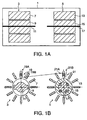
- a motor according to this invention is provided with a first motor unit 3 and a second motor unit 5 loaded into the same casing 1.
- the first motor unit 3 is a reluctance motor comprising a first stator 7 and a first rotor 9.
- the second motor unit 5 is a synchronized motor comprising a second stator 13 and a second rotor 15.
- the first stator 7 and a second stator 13 have the same cylindrical shape.
- the first rotor 9 is disposed on an inner side of the first stator 7 with a predetermined clearance therefrom.
- the second rotor 15 is disposed on an inner side of the second stator 13 with a predetermined clearance therefrom.
- the first and second rotors 9, 15 are disposed co-axially.
- the second rotor 15 comprises magnets which provide two N poles and two S poles disposed alternatively at intervals of 90 degrees. As a result, the second rotor 15 has four poles i.e., two pair of poles. In the following explanation, the number of pairs of poles of the second rotor 15 will be represented by a symbol P 2 .
- the first rotor 9 comprises an armature body having two protruding poles.
- the armature body is not magnetized but is made of a material which conducts magnetic flux.
- An iron core may be used as the armature body.
- the first rotor 9 has two poles i.e., a pair of poles. In the following explanation, the number of pairs of poles of the first rotor 9 will be represented by a symbol P 1 .
- the first stator 7 is provided with twelve coils 19.
- the second stator 13 is also provided with twelve coils 21. Since the number of coils of the first stator 7 and the number of coils of the second stator 13 are identical, they will be represented by the common symbol Ps in the following explanation,
- the coils 19 of the first stator 7 generate a rotating magnetic field having a pair of poles by applying a twelve-phase current with a phase difference of 30 degrees.
- the coils of the second stator 13 generate a rotating magnetic field having two pairs of poles by applying a six-phase current with a phase difference of 60 degrees.
- each coil 19 of the first stator 7 is connected with a terminal of the inverter 29.
- the other end 19B of each coil 19 is connected in series with an end 21A of each coil 21 of the second stator 13 through a cable.
- the other end of each coil 21 is connected to a terminating point 21B.
- the inverter 29 is provided with twelve terminals supplying an AC current to twelve pairs of coils 19 and 21.
- the inverter 29 converts a DC current from a battery 31 to AC composite currents I 0 - I 11 and outputs them through the twelve terminals.
- the inverter 29 comprises twenty four transistors and the same number of diodes.
- the inverter 29 may be obtained by modifying a normal three-phase bridge-type inverter into twelve phase.
- Fig. 2 shows a representative circuit layout of the inverter 29.
- the signal given to the base of each transistor, that is to say, to each gate of the inverter 29 is a pulse width modulation (PWM) signal comprising ON and OFF signals and is output from the control unit 27.
- PWM pulse width modulation
- Signals are input into the control unit 17 from a first position sensor 23 detecting a rotation position ⁇ 1 of the first rotor 9 and a second position sensor 25 detecting a rotation position ⁇ 2 of the second rotor 15.
- Command signals related to the rotational velocity or the output torque of the rotors 9 and 13 are also input into the control unit 27 through an input device, not shown.
- the control unit 27 outputs PWM signals so that the first stator 7 forms a rotating magnetic field with respect to the first rotor 9 and the second stator 13 forms a rotating magnetic field with respect to the second rotor 15 based on the command signal and the position signals ⁇ 1 and ⁇ 2 .
- the inverter 29 generates twelve-phase composite AC currents I 0 - I 11 with a phase difference of 30 degrees by switching the transIstors based on the PWM signals and supplies the currents to the first stator 7 and the second stator 13.
- control unit 27 The operation of the control unit 27 will be described in detail below.
- P 1 number of pairs of poles of first rotor 9.
- LA and LB in Equation (2) represent components of the self-inductance L n .
- LA is a component unrelated to the rotor position and LB is a component which varies according to the rotation position of the rotor.
- the flux linkage ⁇ n of each coil 21 of the second stator 13 which depends on the magnet of the second rotor 15 is represented by Equation (3).
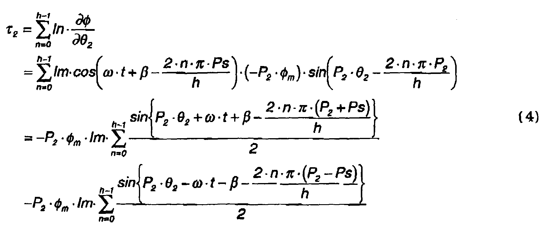
- Equation (4) a torque ⁇ 2 (instantaneous torque) applied to the second rotor 15 is calculated by Equation (4).
- Equation (4) can be expressed as Equation (5).
- ⁇ 2 P 2 ⁇ m ⁇ Im 2 ⁇ h ⁇ sin ⁇
- Equation (7) the component in ⁇ of Equation (5) is expressed in Equation (7). ⁇ sin P 2 ⁇ 2 - ⁇ t - ⁇ - 4 ⁇ n ⁇ ( P 2 - Ps ) h
- Equation (7) can be rewritten as Equation (8).
- Equation (8) ⁇ sin P 2 ⁇ 2 - ⁇ t - ⁇ - n ⁇ 3 0 ⁇ n ⁇ 11
- Equation (8) has a value of zero. Therefore when P 2 ⁇ Ps , ⁇ 2 is zero. That is to say, the torque ⁇ 2 is applied to the second rotor 15 only when the number of pairs of poles Ps of the rotating magnetic field generated by the coils 21 of the second stator 13 is equal to the number of pairs of poles P 2 of the second rotor 15.
- the torque ⁇ 1 (instantaneous torque) generated by the first rotor 9 is calculated by Equation (9).
- ⁇ 1 P 1 ⁇ L 2 ⁇ Im 2 2 ⁇ h ⁇ sin 2 ⁇
- Equation (12) the component in ⁇ of Equation (10) is expressed in Equation (12). ⁇ sin 2 ⁇ P 1 ⁇ 1 - 2 ⁇ t - 2 ⁇ - 4 ⁇ n ⁇ ( P 1 - Ps ) h
- Equation (12) can be rewritten as Equation (13). ⁇ sin 2 ⁇ n ⁇ - 2 ⁇ t - 2 ⁇ - 2 ⁇ n ⁇ 3 0 ⁇ n ⁇ 11
- Equation (13) has a value of zero. Therefore when P 1 ⁇ Ps , ⁇ 1 is zero. That is to say, the torque ⁇ 1 is applied to the first rotor 9 only when the number of pair of poles Ps of the rotating magnetic field generated by the coils 19 of the first stator 7 is equal to the number of pairs of poles P 1 of the first rotor 9.
- a composite current I n comprising the current for the second stator 13 to create the rotating magnetic field which exerts the torque ⁇ 2 on the second rotor 15, and the current for the first stator 7 to create the rotating magnetic field which exerts the torque ⁇ 1 on the first rotor 9.
- I n Im 1 ⁇ cos ⁇ 1 ⁇ 1 - 2 ⁇ n ⁇ P 1 h + Im 2 ⁇ cos ⁇ 2 ⁇ 2 - 2 ⁇ n ⁇ P 2 h
- Equation 15 P 1 ⁇ Im 1 2 2 ⁇ h ⁇ sin 2 ⁇ 1
- torque ⁇ 1 applied by the first stator 7 on the first rotor 9 can be controlled by the phase difference ⁇ 1 of the first term of Equation (14).
- torque ⁇ 2 applied by the second stator 13 on the second rotor 15 can be controlled by the phase difference ⁇ 2 of the second term of Equation (14).
- the number of coils h of the first stator 7 and the second stator 13 is twelve, the number of pairs of poles P 1 of the first rotor 9 is one and the number of pairs of poles P 2 of the second rotor 15 is two.
- Equation (17) the torque ⁇ 1 of the first rotor 9 from Equation (15) is expressed by Equation (17) and the torque ⁇ 2 of the second rotor 15 is expressed by Equation (18).
- the control unit 27 determines the phase differences ⁇ 1 and ⁇ 2 based on the torque ⁇ 1 of the first rotor 9 and the torque ⁇ 2 of the second rotor 15 which are determined on the basis of the command signal, and outputs PWM signals to the inverter so that a corresponding composite current I n is obtained.
- the two motor units 3 and 5 can be rotated independently by applying the composite current I n generated by the single inverter 29 to the coils 19 of the first stator 7 and the coils 21 of the second stator 13.
- the ratio of the number of poles of the first rotor 9 and the number of poles of the second rotor 15 is set to 1:2.
- this invention may be applied to a case where two rotors 9 and 15 constitute the generator units.
- this invention may also be applied to a case where one rotor serves as a generator for generating power while the other rotor serves as a motor rotating by the generated power.
- energy supplied from the inverter or energy regenerated through the inverter by rotation of the rotor is equal to the difference of the energy driving the motor and the electrical energy generated by the generator.
- the capacity of the inverter 29 can be reduced since the inverter only needs to regenerate or supply energy equal to this difference.
- a third rotor 57 is used instead of the second rotor 15 of the first embodiment.
- the third rotor 57 comprises an armature body with four protruding poles, i.e., two pairs of poles, which is not magnetized but made of a material which conducts magnetic flux.
- the second stator 13 generates a rotating magnetic field of which the number of pairs of poles is one by applying a twelve-phase current with a phase difference of 30 degrees in the same manner as the first embodiment.
- a rotating magnetic field of which the number of pairs of poles is two is generated by applying a six-phase current with a phase difference of 60 degrees.
- Equation (2) The principle of the rotational torque that the energized second stator 13 exerts on the third rotor 57 is expressed by Equation (2) which calculates the self-Inductance L n .
- an armature body having a plurality of protruding poles made of a magnetic material not magnetized may be used for both of the two rotors.
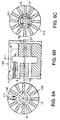
- a single stator 100 is used instead of the first stator 7 and the second stator 13 used in the first embodiment.
- the stator 100 is provided with a cylindrical body 101 and twelve teeth 102 protecting from the body 101 towards the center, Coils 103 are respectively wound on the teeth 102.
- the stator 100 is of a length in an axial direction which covers the first rotor 9 and the second rotor 15.
- This embodiment also enables independent rotation of the first rotor 9 and the second rotor 15 by controlling a composite current which is supplied to the coils 103 of the stator 100.
- a stator 110 of a different shape is used instead of the stator 100 of the third embodiment.
- the stator 110 is provided with twelve separated cores 111 which are separated in the circumferential direction as shown in FIGs. 6B and 6C.
- the separated cores 111 have a longitudinal cross section in the shape of a letter "U" as shown in FIG. 4A, with a coil 112 wound on one end facing the first rotor 9. Coils are not wound on the other end facing the second rotor 15.
- the magnetic flux generated in response to the current of the coils 112 flows towards the first rotor 9 as shown by the arrow in FIG. 6A and it also flows towards the second rotor 15 via the inner section of the separated cores 111.
- the concentration of the magnetic flux in the magnet is reduced due to a demagnetization effect that occurs when the same magnetic poles of the two rotors are opposed via the separated cores 111.
- This demagnetization effect may cause deterioration in the magnetic properties of the magnet.
- at least one of the rotors is made of a magnetic material not magnetized as in the above embodiments, deterioration of the magnet due to demagnetization effect can be avoided.
Landscapes
- Engineering & Computer Science (AREA)
- Power Engineering (AREA)
- Permanent Magnet Type Synchronous Machine (AREA)
Abstract
Description

Claims (10)
- A motor/generator comprising:a first rotor (9) having a plurality of protruding poles made of a magnetic material not magnetized;a second rotor (15, 57) having a plurality of poles;a stator (7, 13, 100, 111) facing the first rotor (9) and the second rotor (15, 57), the stator (7, 13, 100, 111) being provided with a plurality of coils (19,21);an inverter (29) supplying an alternating current to the coils (19, 21) in response to a signal; anda microprocessor (27) programmed to:calculate a first alternating current with which the coils (19, 21) generate a rotating magnetic field rotating in synchronism with the first rotor (9);calculate a second alternating current with which the coils (19, 21) generate a rotating magnetic field rotating in synchronism with the second rotor (15, 57);calculate a composite current comprising the first alternating current and the second alternating current; andoutput a signal corresponding to the composite current to the inverter (29).
- The motor/generator as defined in Claim 1, wherein the second rotor (15, 57) is made of a magnet.
- The motor/generator as defined in Claim 1, wherein the second rotor (15, 57) is made of a magnetic material not magnetized and provided with a plurality of protruding poles.
- The motor/generator as defined in Claim 1, wherein the number of protruding poles of the first rotor (9) differs from the number of poles of the second rotor (15, 57).
- The motor/generator as defined in Claim 1, wherein the number of the coils (19, 21) of the stator (7, 13, 100, 111) is a multiple of the number of the protruding poles of the first rotor (9) and is a multiple of the number of the poles of the second rotor (15).
- The motor/generator as defined in Claim 1, wherein the stator (7, 13, 100, 111) is provided with a plurality of separated cores (111) disposed on a circle, each of the cores (111) is provided with one end facing the first rotor (9) and another end facing the second rotor (15, 57), and the coils (112) are wound on either end of the cores (111).
- The motor/generator as defined in Claim 1, wherein the stator (7, 13, 100, 111) comprises a first stator (7) provided with a lust group of coils (19) facing the first rotor (9) and a second stator (13) provided with a second group of coils (21) facing the second rotor (15, 57), and the coils (19) of the first group and the coils (21) of the second group are connected in series.
- The motor/generator as defined in Claim 1, wherein the rotating magnetic field generated by the first alternating current has magnetic poles of equal number to the protruding poles of the first rotor (9) and the rotating magnetic field generated by the second alternating current has magnetic poles of equal number to the poles of the second rotor (15, 57).
- The motor/generator as defined in Claim 1, wherein the motor/generator further comprises a sensor (23) which detects a rotation position of the first rotor (9), and a sensor (25) which detects a rotation position of the second rotor (15, 57), and the microprocessor (27) is further programmed to calculate the first alternating current based on the rotating position of the first rotor (9), and calculate the second alternating current based on the rotating position of the second rotor (15, 57).
- A motor/generator comprising:a first rotor (9) having a plurality of protruding poles made of a magnetic material not magnetized;a second rotor (15, 57) having a plurality of poles;a stator (7, 13, 100, 111) facing the first rotor (9) and the second rotor (15, 57), the stator (7, 13, 100, 111) being provided with a plurality of coils (19,21);an inverter (29) supplying an alternating current to the coils (19, 21) in response to a signal;means (27) for calculating a first alternating current with which the coils (19, 21) generate a rotating magnetic field rotating in synchronism with the first rotor (9);means (27) for calculating a second alternating current with which the coils (19, 21) generate a rotating magnetic field rotating in synchronism with the second rotor (15, 57);means (27) for calculating a composite current comprising the first alternating current and the second alternating current; andmeans (27) for outputting a signal corresponding to the composite current to the inverter (29).
Applications Claiming Priority (2)
| Application Number | Priority Date | Filing Date | Title |
|---|---|---|---|
| JP27471999 | 1999-09-28 | ||
| JP27471999 | 1999-09-28 |
Publications (3)
| Publication Number | Publication Date |
|---|---|
| EP1089425A2 true EP1089425A2 (en) | 2001-04-04 |
| EP1089425A3 EP1089425A3 (en) | 2003-11-26 |
| EP1089425B1 EP1089425B1 (en) | 2008-07-30 |
Family
ID=17545629
Family Applications (1)
| Application Number | Title | Priority Date | Filing Date |
|---|---|---|---|
| EP00120939A Expired - Lifetime EP1089425B1 (en) | 1999-09-28 | 2000-09-26 | Motor/generator with multiple rotors |
Country Status (3)
| Country | Link |
|---|---|
| US (1) | US6376955B1 (en) |
| EP (1) | EP1089425B1 (en) |
| DE (1) | DE60039666D1 (en) |
Cited By (4)
| Publication number | Priority date | Publication date | Assignee | Title |
|---|---|---|---|---|
| ITBO20090075A1 (en) * | 2009-02-13 | 2010-08-14 | Magneti Marelli Spa | ELECTRIC MACHINE WITH SINGLE STATOR AND TWO ROTORS BETWEEN THEM INDEPENDENT AND ROAD VEHICLE PROVIDED WITH THIS ELECTRIC MACHINE |
| WO2011101501A3 (en) * | 2009-11-11 | 2012-05-18 | Abrahan Conde Mendez | Electrical energy multi-generator |
| CN103580407A (en) * | 2013-11-08 | 2014-02-12 | 北京明正维元电机技术有限公司 | Permanent magnetic synchronous combination motor |
| WO2017086886A3 (en) * | 2015-11-17 | 2017-07-06 | PUREEPASWONG, Phee | Electric generator with a rotational resistance avoidance feature |
Families Citing this family (15)
| Publication number | Priority date | Publication date | Assignee | Title |
|---|---|---|---|---|
| US6472845B2 (en) * | 2000-08-07 | 2002-10-29 | Nissan Motor Co., Ltd. | Motor/generator device |
| JP3818042B2 (en) * | 2000-10-16 | 2006-09-06 | 日産自動車株式会社 | Control device for rotating electrical machine |
| US6717281B1 (en) * | 2000-10-26 | 2004-04-06 | Dennis Brandon | Electric generator and motor drive system |
| US6713889B2 (en) * | 2001-04-27 | 2004-03-30 | Siemens Aktiengesellschaft | Motor-generator system for a motor vehicle with hybrid traction drive |
| US6646394B2 (en) * | 2001-07-09 | 2003-11-11 | Nissan Motor Co., Ltd. | Control device for plurality of rotating electrical machines |
| JP3671910B2 (en) | 2002-01-16 | 2005-07-13 | 日産自動車株式会社 | Connection method of rotating electric machine |
| JP2003244992A (en) * | 2002-02-21 | 2003-08-29 | Nissan Motor Co Ltd | Current control method for rotating electric machine |
| JP3757890B2 (en) * | 2002-04-01 | 2006-03-22 | 日産自動車株式会社 | Driving method of rotating electric machine |
| US6932367B2 (en) | 2002-10-16 | 2005-08-23 | Vistoen Global Technologies, Inc. | Integrated motor |
| JP4712585B2 (en) * | 2006-03-22 | 2011-06-29 | 本田技研工業株式会社 | Electric motor control device |
| JP4754379B2 (en) * | 2006-03-22 | 2011-08-24 | 本田技研工業株式会社 | Electric motor control device |
| FR2915523A1 (en) * | 2007-04-27 | 2008-10-31 | Snecma Sa | DEVICE FOR GENERATING ELECTRIC ENERGY IN A DOUBLE-BODY GAS TURBINE ENGINE |
| US8258737B2 (en) * | 2009-06-24 | 2012-09-04 | Casey John R | Electric machine with non-coaxial rotors |
| KR102855900B1 (en) * | 2020-12-21 | 2025-09-04 | 현대자동차주식회사 | Motor apparatus |
| CN116054517A (en) * | 2021-10-26 | 2023-05-02 | 励富创瑞士控股有限公司 | Energy-saving brushless micro-starter generator |
Family Cites Families (10)
| Publication number | Priority date | Publication date | Assignee | Title |
|---|---|---|---|---|
| US5719456A (en) * | 1994-05-18 | 1998-02-17 | Dana Corporation | Variable reluctance electric motor |
| JP2943657B2 (en) * | 1994-08-02 | 1999-08-30 | トヨタ自動車株式会社 | Control device for salient pole type permanent magnet motor |
| JP3052786B2 (en) * | 1995-06-09 | 2000-06-19 | 株式会社デンソー | Vehicle drive device and drive control method thereof |
| EP1630025B1 (en) * | 1995-05-19 | 2008-02-20 | Toyota Jidosha Kabushiki Kaisha | Power output apparatus and method of controlling the same |
| US5793136A (en) * | 1996-06-05 | 1998-08-11 | Redzic; Sabid | Differential motor/generator apparatus |
| JP3292688B2 (en) * | 1997-11-25 | 2002-06-17 | 株式会社東芝 | Rotating electric machine, hybrid drive device including the same, and operation method thereof |
| JP3480301B2 (en) * | 1998-03-25 | 2003-12-15 | 日産自動車株式会社 | Rotating electric machine |
| EP0945964B1 (en) * | 1998-03-25 | 2003-11-12 | Nissan Motor Co., Ltd. | Motor/generator |
| EP0945963B1 (en) * | 1998-03-25 | 2003-11-05 | Nissan Motor Co., Ltd. | Motor/generator |
| US6097118A (en) * | 1998-10-30 | 2000-08-01 | University Of Chicago | Reluctance apparatus for flywheel energy storage |
-
2000
- 2000-09-26 EP EP00120939A patent/EP1089425B1/en not_active Expired - Lifetime
- 2000-09-26 DE DE60039666T patent/DE60039666D1/en not_active Expired - Lifetime
- 2000-09-27 US US09/670,618 patent/US6376955B1/en not_active Expired - Fee Related
Cited By (9)
| Publication number | Priority date | Publication date | Assignee | Title |
|---|---|---|---|---|
| ITBO20090075A1 (en) * | 2009-02-13 | 2010-08-14 | Magneti Marelli Spa | ELECTRIC MACHINE WITH SINGLE STATOR AND TWO ROTORS BETWEEN THEM INDEPENDENT AND ROAD VEHICLE PROVIDED WITH THIS ELECTRIC MACHINE |
| EP2219285A1 (en) | 2009-02-13 | 2010-08-18 | Magneti Marelli S.p.A. | Electric machine with single stator and two mutually independent rotors, and road vehicle provided with said electric machine |
| US8222784B2 (en) | 2009-02-13 | 2012-07-17 | MAGNETI MARELLI S.p.A. | Electric machine with single stator and two mutually independent rotors, and road vehicle provided with said electric machine |
| WO2011101501A3 (en) * | 2009-11-11 | 2012-05-18 | Abrahan Conde Mendez | Electrical energy multi-generator |
| CN102648568A (en) * | 2009-11-11 | 2012-08-22 | 亚伯拉罕·康德门德斯 | Power generator set |
| CN103580407A (en) * | 2013-11-08 | 2014-02-12 | 北京明正维元电机技术有限公司 | Permanent magnetic synchronous combination motor |
| WO2017086886A3 (en) * | 2015-11-17 | 2017-07-06 | PUREEPASWONG, Phee | Electric generator with a rotational resistance avoidance feature |
| RU2737351C2 (en) * | 2015-11-17 | 2020-11-27 | Туангсин ПУРИПАСВОНГ | Electric generator with rotary resistance reduction function |
| US11025153B2 (en) | 2015-11-17 | 2021-06-01 | Phee PUREEPASWONG | Electric generator with a rotational resistance avoidance feature |
Also Published As
| Publication number | Publication date |
|---|---|
| EP1089425A3 (en) | 2003-11-26 |
| DE60039666D1 (en) | 2008-09-11 |
| EP1089425B1 (en) | 2008-07-30 |
| US6376955B1 (en) | 2002-04-23 |
Similar Documents
| Publication | Publication Date | Title |
|---|---|---|
| US6376955B1 (en) | Motor/generator with multiple rotors | |
| EP2001121B1 (en) | Engine start system with quadrature AC excitation | |
| EP0467517B1 (en) | Dual-stator induction synchronous motor | |
| US6429562B2 (en) | Motor/generator | |
| US6236172B1 (en) | Driving system for electric vehicle | |
| EP2107665A2 (en) | Permanent magnet dynamoelectric machine with variable magnetic flux excitation | |
| KR940000306A (en) | AC variable speed drive device and electric vehicle drive system using the device | |
| US6335606B1 (en) | Control device and method for motor/generator | |
| US10193428B2 (en) | Electric rotating machine | |
| EP0529873B1 (en) | Brushless induction synchronous motor with two stators | |
| EP3288180A1 (en) | Circuit and control method for the same | |
| US20030127931A1 (en) | Generator motor having inductor rotor | |
| EP1713163A1 (en) | Ipm rotating electric machine | |
| US4110669A (en) | Synchronous machine control system | |
| US4445081A (en) | Leading power factor induction motor device | |
| EP1330020B1 (en) | Electric rotating machine and its connecting method | |
| US12278523B2 (en) | Electrical machine | |
| US10756661B2 (en) | Field winding type rotating electric machine | |
| JP3289635B2 (en) | Permanent magnet rotating electric machine | |
| JPH11332277A (en) | Permanent magnet type motor and its control device | |
| JP2876738B2 (en) | Series-parallel switching rotary electric machine | |
| KR950008389B1 (en) | Armature winding method of AC servo motor | |
| JP3413816B2 (en) | Synchronous motor | |
| JP2006158166A (en) | Sensorless synchronous motor, and its driving method and device | |
| JP5412121B2 (en) | Permanent magnet rotor and electric motor equipped with the same |
Legal Events
| Date | Code | Title | Description |
|---|---|---|---|
| PUAI | Public reference made under article 153(3) epc to a published international application that has entered the european phase |
Free format text: ORIGINAL CODE: 0009012 |
|
| 17P | Request for examination filed |
Effective date: 20000926 |
|
| AK | Designated contracting states |
Kind code of ref document: A2 Designated state(s): AT BE CH CY DE DK ES FI FR GB GR IE IT LI LU MC NL PT SE |
|
| AX | Request for extension of the european patent |
Free format text: AL;LT;LV;MK;RO;SI |
|
| PUAL | Search report despatched |
Free format text: ORIGINAL CODE: 0009013 |
|
| AK | Designated contracting states |
Kind code of ref document: A3 Designated state(s): AT BE CH CY DE DK ES FI FR GB GR IE IT LI LU MC NL PT SE |
|
| AX | Request for extension of the european patent |
Extension state: AL LT LV MK RO SI |
|
| AKX | Designation fees paid |
Designated state(s): DE FR GB |
|
| 17Q | First examination report despatched |
Effective date: 20040929 |
|
| GRAP | Despatch of communication of intention to grant a patent |
Free format text: ORIGINAL CODE: EPIDOSNIGR1 |
|
| RIC1 | Information provided on ipc code assigned before grant |
Ipc: H02P 5/74 20060101AFI20080117BHEP |
|
| GRAS | Grant fee paid |
Free format text: ORIGINAL CODE: EPIDOSNIGR3 |
|
| GRAA | (expected) grant |
Free format text: ORIGINAL CODE: 0009210 |
|
| AK | Designated contracting states |
Kind code of ref document: B1 Designated state(s): DE FR GB |
|
| REG | Reference to a national code |
Ref country code: GB Ref legal event code: FG4D |
|
| REF | Corresponds to: |
Ref document number: 60039666 Country of ref document: DE Date of ref document: 20080911 Kind code of ref document: P |
|
| PLBE | No opposition filed within time limit |
Free format text: ORIGINAL CODE: 0009261 |
|
| STAA | Information on the status of an ep patent application or granted ep patent |
Free format text: STATUS: NO OPPOSITION FILED WITHIN TIME LIMIT |
|
| 26N | No opposition filed |
Effective date: 20090506 |
|
| PGFP | Annual fee paid to national office [announced via postgrant information from national office to epo] |
Ref country code: FR Payment date: 20100921 Year of fee payment: 11 |
|
| PGFP | Annual fee paid to national office [announced via postgrant information from national office to epo] |
Ref country code: GB Payment date: 20100922 Year of fee payment: 11 |
|
| PGFP | Annual fee paid to national office [announced via postgrant information from national office to epo] |
Ref country code: DE Payment date: 20100922 Year of fee payment: 11 |
|
| GBPC | Gb: european patent ceased through non-payment of renewal fee |
Effective date: 20110926 |
|
| REG | Reference to a national code |
Ref country code: FR Ref legal event code: ST Effective date: 20120531 |
|
| REG | Reference to a national code |
Ref country code: DE Ref legal event code: R119 Ref document number: 60039666 Country of ref document: DE Effective date: 20120403 |
|
| PG25 | Lapsed in a contracting state [announced via postgrant information from national office to epo] |
Ref country code: DE Free format text: LAPSE BECAUSE OF NON-PAYMENT OF DUE FEES Effective date: 20120403 |
|
| PG25 | Lapsed in a contracting state [announced via postgrant information from national office to epo] |
Ref country code: GB Free format text: LAPSE BECAUSE OF NON-PAYMENT OF DUE FEES Effective date: 20110926 Ref country code: FR Free format text: LAPSE BECAUSE OF NON-PAYMENT OF DUE FEES Effective date: 20110930 |