EP1089400A2 - Connector with primary molded member and secondary molded member - Google Patents
Connector with primary molded member and secondary molded member Download PDFInfo
- Publication number
- EP1089400A2 EP1089400A2 EP00710023A EP00710023A EP1089400A2 EP 1089400 A2 EP1089400 A2 EP 1089400A2 EP 00710023 A EP00710023 A EP 00710023A EP 00710023 A EP00710023 A EP 00710023A EP 1089400 A2 EP1089400 A2 EP 1089400A2
- Authority
- EP
- European Patent Office
- Prior art keywords
- molded member
- protrusion
- primary molded
- secondary resin
- primary
- Prior art date
- Legal status (The legal status is an assumption and is not a legal conclusion. Google has not performed a legal analysis and makes no representation as to the accuracy of the status listed.)
- Granted
Links
- 239000011347 resin Substances 0.000 claims abstract description 93
- 229920005989 resin Polymers 0.000 claims abstract description 93
- 238000005192 partition Methods 0.000 claims abstract description 6
- 230000002093 peripheral effect Effects 0.000 claims description 7
- NJPPVKZQTLUDBO-UHFFFAOYSA-N novaluron Chemical compound C1=C(Cl)C(OC(F)(F)C(OC(F)(F)F)F)=CC=C1NC(=O)NC(=O)C1=C(F)C=CC=C1F NJPPVKZQTLUDBO-UHFFFAOYSA-N 0.000 claims description 6
- 239000002184 metal Substances 0.000 claims description 3
- 230000008018 melting Effects 0.000 abstract description 56
- 238000002844 melting Methods 0.000 abstract description 56
- 238000002347 injection Methods 0.000 description 23
- 239000007924 injection Substances 0.000 description 23
- 239000000446 fuel Substances 0.000 description 22
- 238000000465 moulding Methods 0.000 description 21
- 230000003247 decreasing effect Effects 0.000 description 11
- 230000006866 deterioration Effects 0.000 description 3
- 239000004677 Nylon Substances 0.000 description 2
- 230000004048 modification Effects 0.000 description 2
- 238000012986 modification Methods 0.000 description 2
- 229920001778 nylon Polymers 0.000 description 2
- XLYOFNOQVPJJNP-UHFFFAOYSA-N water Substances O XLYOFNOQVPJJNP-UHFFFAOYSA-N 0.000 description 2
- 238000002485 combustion reaction Methods 0.000 description 1
- 239000004020 conductor Substances 0.000 description 1
- 230000004927 fusion Effects 0.000 description 1
- 230000035939 shock Effects 0.000 description 1
Images



Classifications
-
- H—ELECTRICITY
- H01—ELECTRIC ELEMENTS
- H01R—ELECTRICALLY-CONDUCTIVE CONNECTIONS; STRUCTURAL ASSOCIATIONS OF A PLURALITY OF MUTUALLY-INSULATED ELECTRICAL CONNECTING ELEMENTS; COUPLING DEVICES; CURRENT COLLECTORS
- H01R43/00—Apparatus or processes specially adapted for manufacturing, assembling, maintaining, or repairing of line connectors or current collectors or for joining electric conductors
- H01R43/20—Apparatus or processes specially adapted for manufacturing, assembling, maintaining, or repairing of line connectors or current collectors or for joining electric conductors for assembling or disassembling contact members with insulating base, case or sleeve
- H01R43/24—Assembling by moulding on contact members
-
- H—ELECTRICITY
- H01—ELECTRIC ELEMENTS
- H01R—ELECTRICALLY-CONDUCTIVE CONNECTIONS; STRUCTURAL ASSOCIATIONS OF A PLURALITY OF MUTUALLY-INSULATED ELECTRICAL CONNECTING ELEMENTS; COUPLING DEVICES; CURRENT COLLECTORS
- H01R13/00—Details of coupling devices of the kinds covered by groups H01R12/70 or H01R24/00 - H01R33/00
- H01R13/40—Securing contact members in or to a base or case; Insulating of contact members
- H01R13/405—Securing in non-demountable manner, e.g. moulding, riveting
Definitions
- the present invention relates to a connector used for a connection of electrical members, which is suitably applied to a fuel injection valve of a diesel engine, for example. More particularly, the present invention relates to a connector with a primary molded member made of a primary resin and a secondary molded member made of a secondary resin, which is formed by filling the secondary resin into a molding die in which the primary molded member is inserted.
- a melting portion to be fusion-bonded to a secondary molded member is provided in a primary molded member, so that seal performance of the connector at a boundary between the primary molded member and the secondary molded member is improved by fusion-bonding the primary molded member and the secondary molded member. That is, as the melting portion, a recess portion is simply provided on a surface of the primary molded member, facing the secondary molded member. Therefore, when the conventional connector has simple structures of the primary molded member and the secondary molded member described in JP-U-61-70016, a water instruction from the boundary between the primary molded member and the secondary molded member can be prevented by the melting of the melting portion.
- the connector has a complex structure, for example, when the connector is used for a fuel injection valve, it is difficult to completely seal a connection portion between the primary molded member and the secondary molded member, and an electrical short circuit between electrical members within the secondary molded member or between an electrical member within the secondary molded member and a metal member outside the secondary molded member may be caused.
- the secondary molded member in a connector with a primary molded member and a secondary molded member, the secondary molded member is disposed to enclose the primary molded member.
- the secondary molded member is made of a secondary resin filled between the primary molded member and a die disposed to have a predetermined clearance with the primary molded member, and a protrusion member is provided on an outer surface of the primary molded member to partition electrical conductive members.
- the protrusion member is melted during a filling of the secondary resin to be fusion-bonded to the secondary molded member.
- the fusion-bonding performance between the primary molded member and the secondary molded member is improved, while an electrical short circuit between the electrical conductive members is prevented.
- the primary molded member is disposed within the die to have a distance D between an outer surface of the primary molded member and an inner surface of the die, before the filling of the secondary resin for the secondary molded member, and the distance D is equal to or larger than 1 mm and is smaller than 2 mm. Therefore, a flow rate of the secondary resin during the filling of the secondary resin is increased, and pressure of the secondary resin is increased around the protrusion member. By increasing the pressure of the secondary resin, a decrease of the temperature of the secondary resin is prevented, and it is not necessary to increase the temperature of the secondary resin during the filling of the secondary resin.
- the distance D is set in such a manner that the protrusion member is melted by the secondary resin having a predetermined temperature and a predetermined pressure during the filling of the secondary resin.
- the fusion-bonding performance between the primary molded member and the secondary molded member is further improved, and a connection portion between the primary molded member and the secondary molded member can be accurately sufficiently sealed.
- a resin injection nozzle for filling the secondary resin can be used in a long time, and a dimension deformation of the secondary molded member can be prevented.
- a connector 40 shown in FIG. 1 is typically applied to a fuel injection valve 1 shown in FIG. 2 for a diesel engine.
- the fuel injection valve 1 is for injecting fuel having a predetermined high pressure into a combustion chamber of the diesel engine.
- the fuel injection valve 1 includes a valve body 13 having a fuel injection nozzle 10, a valve needle 12 for opening and closing an injection hole 11 formed at a top end of the fuel injection nozzle 10, a control piston 14 disposed in the valve body 13 to drive the valve needle 12, a pressure control chamber 15 in which a high-pressure fuel is stored to press the control piston 14 in a direction closing the injection hole 11, an electromagnetic valve 20 for interrupting a flow of high-pressure fuel from the pressure control chamber 15 to a low-pressure part 16, and the connector 40 for supplying electrical power.
- the electromagnetic valve 20 is an electromagnetic two-way valve for interrupting the pressure control chamber 15 and the low-pressure part 16.
- An electromagnetic coil 21 is wound within a stator 22, and is disposed so that electrical power from the connector 40 is supplied thereto.
- a valve member 23 of the electromagnetic valve 20 is slidably held in an inner wall of a cylinder 24.
- An armature 25 is fixed to the valve member 23 at a side of the stator 22.
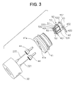
- the connector 40 As shown in FIG. 2, the connector 40 is connected to the electromagnetic valve 20 at a side opposite to the injection hole 11. As shown in FIGS. 1 and 3, the connector 40 includes a housing 41 used as a pedestal member, a primary molded member 50, a positive terminal 42 used as a positive electrode member, a negative terminal 43 used as a negative electrode member, and a secondary molded member 60.
- the housing 41 is made of metal, and is integrally connected to the stator 22 enclosing therein the electromagnetic coil 21, by a laser melting, for example.
- Connection terminals 221, 222 to be connected to the electromagnetic coil 21 are provided in the stator 22.
- the connection terminals 221, 222 of the stator 22 penetrate through holes 41a provided in the housing 41, and protrude from the housing 41 at a side opposite to the stator 22. Further, as shown in FIG. 3, bushes 44 are provided on the connection terminals 221, 222, respectively, so that the stator 22 and the housing 41 are electrically insulated from each other.
- a body part 51 is formed into an approximate T-shape in cross-section by a primary resin having heat-plasticity such as nylon.
- the positive terminal 42 and the negative terminal 43 made of an electrical conductive material are provided in the primary molded member 50. As shown in FIG. 3, the positive terminal 42 and the negative terminal 43 are provided to protrude from one surface (hereinafter, the one surface is referred to as "front surface) of the body part 51.
- the positive terminal 42 and the negative terminal 42 has connection terminal portions 421, 431 connected to the connection terminals 221, 222, and supply terminal portions 422, 432 connected to an electrical power source (not shown).
- the other parts of the positive terminal 42 and the negative terminal 43, except for the supply terminal portions 422, 433 and the connection terminal portions 421, 431, are inserted within the body part 51 of the primary molded member 50.
- the primary molded member 50 has position determining portions 52, and the position determining portions 52 are respectively inserted into position determining holes 412 provided in the housing 41 as shown in FIG. 1.
- the connection terminals 221, 222 protruding from the housing 41 are close to the connection terminal portion 421 of the positive terminal 42 and the connection terminal portion 431 of the negative terminal 43. Accordingly, the connection terminals 221, 222 are readily fusion-bonded to the connection terminal portions 421, 431 of the positive terminal 42 and the negative terminal 43, and the connection positions thereof can be readily determined.
- a melting protrusion 53 is formed in the body part 51 of the primary molded member 50.
- the melting protrusion 53 is disposed on an outer peripheral surface of the body part 51 to separate the electrical conductive parts from each other.
- the melting protrusion 53 includes a first protrusion portion 531, a second protrusion portion 532 and a third protrusion portion 533.
- the first protrusion portion 531 is formed on the front surface of the body part 51 to extend in an axial direction of the body part 51, and to partition the connection terminal portion 421 of the positive terminal 42 and the connection terminal portion 431 of the negative terminal 43 at an approximate center position between both the connection terminal portions 431, 432.
- the first protrusion portion is disposed for preventing an electrical short circuit between the connection terminal portion 421 of the positive terminal 42 and the connection terminal portion 431 of the negative terminal 43.
- the second protrusion portion 532 is provided continuously along an outer peripheral surface of the body part 51 in a direction approximately perpendicular to the first protrusion portion 531, and is connected to an upper end of the first protrusion portion 531. That is, the second protrusion portion 532 is provided continuously on the outer peripheral surface of the body part 51 to be approximately perpendicular to the axial direction of the body part 51.
- the second protrusion portion 532 is disposed to prevent an electrical short circuit between the supply terminal portions 422, 432 of the positive terminal 42 and the negative terminal 43 and the housing 41, and to prevent an electrical short circuit between the connection terminal portions 421, 431 and the supply terminal portions 422, 432 of the positive terminal 42 and the negative terminal 43.
- the third protrusion portion 533 is provided on the body part 51 continuously from both side end parts of the front surface of the body part 51 on side surfaces of the body part 51 to bottom end of the body part 51, so that top ends of the third protrusion portion 533 are connected to the second protrusion portion 532. That is, the third protrusion portion 533 has both side end parts extending in the axial direction of the body part 51 to be connected to the second protrusion portion 532, and bottom end part provided on a bottom end of the body part 51 to be connected to the side end parts.
- the third protrusion portion 533 is disposed to prevent an electrical short circuit between the housing 41 and both the connection terminal portions 421, 431 of the positive terminal 42 and the negative terminal 43, and to prevent an electrical short circuit between the connection terminal portion 421 of the positive terminal 42 and the connection terminal portion 431 of the negative terminal 43.
- An upper protrusion portion 551 is provided on an upper ends of side surfaces of the body part 51 and a rear surface of the body part 51, at a position upper than the second protrusion portion 532.
- the side surfaces of the body part 51 are placed at both sides of the front surface, and the rear surface of the body part 51 is placed at a side opposite to the front surface of the body part 51.
- the upper protrusion portion 551 is formed continuously from the both side surfaces of the body part 51 to the rear surface of the body part 51 to be parallel to the second protrusion portion 532.
- a lower protrusion portion 552 is formed at a position lower than the second protrusion portion 532 on the rear surface and end parts of the side surfaces of the body part 51.
- a horizontal part of the lower protrusion portion 552 is continuously provided to parallel to the second protrusion portion 532.
- a vertical part of the lower protrusion portion 552 is provided in the axial direction of the body part 51 to parallel to the side end parts of the third protrusion portion 533.
- the second protrusion portion 532 and the third protrusion portion 533 are disposed to be inserted by the upper protrusion portion 551 and the lower protrusion portion 552 at both upper and lower end sides. Further, each protrusion dimension (i.e., protrusion height) of the upper protrusion portion 551 and the lower protrusion portion 552 is made smaller than that of the melting protrusion 53, while sectional areas of the upper protrusion portions 551 and the lower protrusion portion 552 become larger than that of the melting protrusion 53.
- a distance between both the upper and lower protrusion portions 551, 552 and a molding die 70 described later is made larger than a distance between the melting protrusion 53 and the molding die 70. Therefore, temperature of a secondary resin is hardly increased around the upper protrusion portion 551 and the lower protrusion portion 552, and the upper protrusion portion 551 and the lower protrusion portion 552 are not melted by the secondary resin.
- the upper protrusion portion 551 and the lower protrusion portion 552 are formed so that the second protrusion portion 532 and the third protrusion 533 are inserted from upper and lower sides by the upper protrusion portion 551 and the lower protrusion portion 552, a stress is not directly applied to a melting position of the second protrusion portion 532 and the third protrusion portion 533, even when a secondary resin expends or contracts due to a temperature variation after a filling of the secondary resin.
- the secondary molded member 60 shown in FIG. 1 is made of the secondary resin, and is formed to cover around the primary molded member 50.
- the secondary resin for example, a heat-plasticity resin such as nylon can be used, similarly to the primary resin.
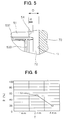
- FIG. 5 is an enlarged schematic view of the A part shown in FIG. 1.
- the molding die 70 is disposed to have a predetermined clearance between the molding die 70 and the primary molded member 50.
- a distance D between the surface 54 of the body part 51 of the primary molded member 50, on which the melting protrusion 53 is formed, and an inner wall surface 71 of the molding die 70 is set in a range of 1 mm ⁇ D ⁇ 2 mm. That is, a wall thickness T of the secondary molded member 60 is approximately equal to the distance D, and is set in a range of 1 mm ⁇ T ⁇ 2 mm.
- the wall thickness T of the secondary molded member 60 is approximately uniform around the primary molded member 50.
- the protrusion dimension d of the melting protrusion 53 is approximately 0.5 mm, for example.
- the distance D and the protruding dimension (height) d will be now described.
- a melting ratio (fusion-bonding strength) R of the melting protrusion 53 of the primary molded member 50 is decreased.
- the melting ratio (fusion-bonding strength) R is calculated by the following formula (1).
- the melting ratio R indicates a fusion-bonding ratio between the melting protrusion 53 of the primary molded member 50 and the secondary molded member 60.
- the melting ratio R is about 60 %.
- the melting ratio R is about 20 %.
- the clearance 72 is readily filled with the secondary resin. Therefore, a flow velocity of the secondary resin is decreased, and pressure of the secondary resin passing through the clearance 72 around the melting protrusion 53 is slightly increased. Since the pressure of the secondary resin around the melting portion 53 is greatly not increased, the temperature of the secondary resin around the melting protrusion 53 is decreased. As a result, it is difficult to melt the melting protrusion 53, the melting ratio R is decreased, and a fusion bonding between the melting protrusion 53 of the primary molded member 50 and the secondary molded member 60 made of the secondary resin becomes insufficient.
- a flow velocity of the secondary resin is increased, and pressure of the secondary resin around the melting protrusion 53 is greatly increased during the filling of the secondary resin. Accordingly, the temperature of the secondary resin proximate to the melting protrusion 53 is prevented from being decreased due to the increased pressure of the secondary resin.
- the melting protrusion 53 can be accurately sufficiently melted, and the melting ratio R is improved.
- the width dimension (i.e., the distance D) of the clearance 72 between the primary molded member 50 and the inner wall surface 71 of the molding die 70 is decreased to become smaller than 1 mm (e.g., D ⁇ 1 mm)
- a flow velocity of the secondary resin is further increased.
- the secondary resin is difficult to pass through the clearance 72, and the flow of the secondary resin around the melting protrusion 53 becomes difficult.
- a ratio of a contact area of the inner wall surface 71 of the molding die 70 relative to the filled amount of the secondary resin is increased, heat of the secondary resin is transmitted to the molding die 70, and the temperature of the secondary resin is decreased. As a result, the filling of the secondary resin becomes insufficient, and the fusion-bonding between the melting protrusion 53 and the secondary resin becomes insufficient.
- the protrusion dimension d (i.e., protrusion height) of the melting protrusion 53 is set to be approximately equal to 0.5 mm.
- the protrusion dimension d becomes larger, the width dimension of the clearance 72 through which the secondary resin flows becomes smaller, and the flow of the secondary resin around the melting protrusion 53 becomes difficult.
- the protrusion dimension d becomes smaller, the width dimension of the clearance 72 through which the secondary resin flows becomes larger, and the flow speed of the secondary resin around the melting protrusion 53 becomes lower. Accordingly, heat capacity of the melting protrusion 53 becomes smaller, and the melting protrusion 53 is difficult to be melted.
- the distance D is set in a range of 1 mm ⁇ T ⁇ 2 mm, the protrusion distance d of the melting protrusion 53 is set approximately at 0.5 mm.
- the temperature of the filling secondary resin can be set to be equal to or lower than 300 °C.
- the flow speed of the secondary resin can be increased.
- a heat deterioration of the secondary resin is increased, a resin injection nozzle for filling the secondary resin is readily deformed, and a dimension deformation of the secondary molded member 60 may be caused.
- the distance between the primary molding member 50 inserted into the molding die 70 and the inner wall surface 71 of the molding die 70 is set in a range of 1 mm ⁇ T ⁇ 2 mm so that the melting protrusion 53 is melted during the filling of the secondary resin by the secondary resin having a predetermined temperature and a predetermined pressure.
- the secondary molded member 60 is formed around the primary molded member 50 to have approximately uniform wall thickness.
- the melting protrusion 53 of the primary molded member 50 can be accurately sufficiently melted.
- a fusion-bonding performance between the primary molded member 50 and the secondary molded member 60 can be improved, and a boundary part between the primary molded member 50 and the secondary molded member 60 can be accurately tightly sealed.
- the temperature of the filling secondary resin is restricted around the melting protrusion 53, it is possible to set the temperature of the filling secondary resin to be equal to or lower than 300 °C. Therefore, heat deterioration of the secondary resin is prevented, a resin injection nozzle for filling the secondary resin can be used in a long time, and a dimension deformation of the secondary molded member 60 can be prevented. Further, it can prevent bubbles from being generated within the secondary molded member 60. As a result, a heat shock resistance of the connector 40 is improved.
- the melting protrusion 53 provided on the outer peripheral part of the primary molded member 50 includes the first protrusion portion 531, the second protrusion portion 532 and the third protrusion portion 533 which are connected to each other.
- the first protrusion portion 531 is provided to partition the connection terminal portion 421 of the positive terminal 42 and the connection terminal portion 431 of the negative terminal 43. Therefore, by the fusion-bonding between the first protrusion portion 531 and the secondary molded member 60, an electrical short circuit generated between the connection terminal portion 421 and the connection terminal portion 431 can be prevented.
- the second protrusion portion 532 is continuously provided around the outer peripheral surface at an approximate center position of the body part 51 in the axial direction of the body part 51. Therefore, by the fusion-bonding between the second protrusion portion 532 and the secondary molded member 60, an electrical short circuit between the supply terminal portions 422, 433 and the housing 41, and an electrical short circuit between the positive terminal 42 and the negative terminal 43 can be prevented.
- the third protrusion portion 533 is provided continuously from the side end part to the bottom end part of the body part 51. Therefore, by the fusion-bonding between the third protrusion portion 533 and the secondary molded member 60, an electrical short circuit between the housing 41 and the connection terminal portions 421, 431, and an electrical short circuit between the connection terminal portion 421 and the connection terminal portion 431 can be prevented. Accordingly, even when water is introduced between the secondary molded member 60 and the housing 41, an electrical short circuit between the electrical conductive members can be prevented.
- the upper protrusion portion 551 and the lower protrusion portion 552 are provided on the primary molded member 50, it can prevent a stress from being directly applied to the fusion-bonding portion (the melting protrusion 53) while the secondary resin for forming the secondary molded member 60 is expanded or is contracted.
- the connector 40 of the present invention is typically applied to the fuel injection valve 1 for a diesel engine.
- the connector 40 of the present invention may be applied to an other electrical unit.
- a distance (D) between the primary molded member and a die (70) is set before a filling of a secondary resin so that a melting protrusion (53) of the primary molded member is melted by a secondary resin having a predetermined temperature and a predetermined pressure during the filling of the secondary resin. Because a wall thickness of the secondary molded member around the primary molded member is made approximately uniform, a flow rate of the secondary resin is increased. Further, the melting protrusion is disposed to partition electrical conductive members from each other, and is accurately sufficiently melted to improve fusion-bonding performance between the primary molded member and the secondary molded member. Accordingly, an electrical short circuit between the electrical conductive members is accurately prevented in the connector.
Landscapes
- Engineering & Computer Science (AREA)
- Manufacturing & Machinery (AREA)
- Injection Moulding Of Plastics Or The Like (AREA)
- Connector Housings Or Holding Contact Members (AREA)
- Fuel-Injection Apparatus (AREA)
- Electrically Driven Valve-Operating Means (AREA)
- Manufacturing Of Electrical Connectors (AREA)
Abstract
Description
Claims (11)
- A connector (40) comprising:a pedestal member (41) made of metal;an electrical terminal member (221, 222) protruding from said pedestal member (41);a primary molded member (50) provided at a side where said terminal member (221, 222) protrudes from said pedestal member (41);a positive electrode member (42, 421, 422) and a negative electrode member (43, 431, 432) disposed in said primary molded member (50) to be connected to said terminal member (221, 222);a secondary molded member (60) disposed to enclose said primary molded member (50), which is formed by a secondary resin filled between said primary molded member (50) and a die (70) disposed to have a predetermined clearance with said primary molded member (50); anda protrusion member (53) provided on an outer surface of said primary molded member (50) to partition said positive electrode member (42, 421, 422) and said negative electrode member (43, 431, 432) protruding from said outer surface, said protrusion member (53) being melted during a filling of said secondary resin to be fusion-bonded to said secondary resin member (60).
- The connector according to claim 1, wherein said secondary molded member (60) is disposed on said pedestal member (41) to be connected to said pedestal member (41) in an axial direction.
- The connector according to claim 2, wherein:said protrusion member (53) has an axial protrusion (531, 533) protruding from said outer surface of said primary molded member (50) between said positive electrode member (421, 422) and said negative electrode member (431, 432); andsaid axial protrusion (531, 533) is provided to extend in said axial direction.
- The connector according to claim 3, wherein said protrusion member (53) further has a peripheral protrusion (532) protruding from said primary molded member (50) continuously in a peripheral direction of said primary molded member (50), approximately perpendicular to said axial direction.
- The connector according to any one of claims 1-4, wherein:said primary molded member (50) is disposed within the die (70) to have a distance D between an outer surface of said primary molded member (50), on which said protrusion member (53) is provided, and an inner surface of the die (70), before the filling of said secondary resin for said secondary molded member (60); andthe distance D is equal to or larger than 1 mm and is smaller than 2 mm.
- The connector according to claim 5, wherein the distance D is set in such a manner that said protrusion member (53) is melted by said secondary resin having a predetermined temperature and a predetermined pressure during the filling of said secondary resin.
- The connector according to any one of claims 1-6, wherein:
said secondary molded member (60) has a wall thickness (T) around said primary molded member (50), said wall thickness (T) being approximately uniform. - The connector according to any one of claims 1-7, wherein temperature of said secondary resin filling between said primary molded member (50) and the die (70) is equal to or lower than 300°C.
- The connector according to any one of claims 1-8, further comprising
an additional protrusion (551, 552) protruding from a surface of said primary molded member (51) at a position proximate to said protrusion member (53),
wherein said additional protrusion (551, 552) has a protrusion height smaller than that of said protrusion member (53), and has a sectional area larger than that of said protrusion member (53). - The connector according to any one of claims 1-9, said primary molded member (51) and said additional protrusion (551, 552) are integrally molded by a primary resin.
- The connector according to any one of claims 1-9, wherein said primary molded member (51) and said protrusion member (53) are integrally molded by a primary resin.
Applications Claiming Priority (2)
| Application Number | Priority Date | Filing Date | Title |
|---|---|---|---|
| JP27909799A JP4186145B2 (en) | 1999-09-30 | 1999-09-30 | connector |
| JP27909799 | 1999-09-30 |
Publications (3)
| Publication Number | Publication Date |
|---|---|
| EP1089400A2 true EP1089400A2 (en) | 2001-04-04 |
| EP1089400A3 EP1089400A3 (en) | 2002-04-17 |
| EP1089400B1 EP1089400B1 (en) | 2007-11-14 |
Family
ID=17606382
Family Applications (1)
| Application Number | Title | Priority Date | Filing Date |
|---|---|---|---|
| EP00710023A Expired - Lifetime EP1089400B1 (en) | 1999-09-30 | 2000-09-28 | Connector with primary molded member and secondary molded member |
Country Status (4)
| Country | Link |
|---|---|
| EP (1) | EP1089400B1 (en) |
| JP (1) | JP4186145B2 (en) |
| DE (1) | DE60037090T2 (en) |
| ES (1) | ES2292420T3 (en) |
Cited By (4)
| Publication number | Priority date | Publication date | Assignee | Title |
|---|---|---|---|---|
| DE102006035347A1 (en) * | 2005-10-14 | 2007-04-26 | Denso Corp., Kariya | Electromagnetic valve and manufacturing process for this |
| WO2011072827A1 (en) * | 2009-12-19 | 2011-06-23 | Bayerische Motoren Werke Aktiengesellschaft | Electric connector and method for producing an electric connector |
| CN107871947A (en) * | 2016-09-27 | 2018-04-03 | 泰科电子(上海)有限公司 | Connecting piece, electrical connector, assembly of connecting terminals, and method for manufacturing the connecting piece |
| CN116845671A (en) * | 2023-08-01 | 2023-10-03 | 东莞市典威电子有限公司 | Photovoltaic connector step-by-step injection molding production equipment and usage methods |
Families Citing this family (3)
| Publication number | Priority date | Publication date | Assignee | Title |
|---|---|---|---|---|
| JP2007064363A (en) * | 2005-08-31 | 2007-03-15 | Denso Corp | Solenoid valve and fuel injection valve equipped with the solenoid valve |
| EP2713040B1 (en) * | 2012-09-26 | 2017-06-07 | Delphi International Operations Luxembourg S.à r.l. | Electrical connector |
| DE102022103918A1 (en) | 2022-02-18 | 2023-08-24 | Thomas Magnete Gmbh | Process for manufacturing an electronic component |
Family Cites Families (5)
| Publication number | Priority date | Publication date | Assignee | Title |
|---|---|---|---|---|
| CA1113980A (en) * | 1979-02-26 | 1981-12-08 | Thomas A. Kutnyak | Vacuum cleaner hose assembly and two stage injection molding method in making same |
| JPH0211148Y2 (en) * | 1984-10-12 | 1990-03-20 | ||
| DE4003228A1 (en) * | 1990-02-03 | 1991-08-22 | Bosch Gmbh Robert | ELECTROMAGNETICALLY ACTUABLE VALVE |
| US5427319A (en) * | 1994-03-24 | 1995-06-27 | Siemens Automotive L.P. | Fuel injector armature assembly |
| FR2741832B1 (en) * | 1995-12-01 | 1998-01-23 | Bost Garnache Ind | METHOD FOR MANUFACTURING A TOOL HANDLE, AND CORRESPONDING TOOL |
-
1999
- 1999-09-30 JP JP27909799A patent/JP4186145B2/en not_active Expired - Lifetime
-
2000
- 2000-09-28 EP EP00710023A patent/EP1089400B1/en not_active Expired - Lifetime
- 2000-09-28 DE DE60037090T patent/DE60037090T2/en not_active Expired - Lifetime
- 2000-09-28 ES ES00710023T patent/ES2292420T3/en not_active Expired - Lifetime
Cited By (7)
| Publication number | Priority date | Publication date | Assignee | Title |
|---|---|---|---|---|
| DE102006035347A1 (en) * | 2005-10-14 | 2007-04-26 | Denso Corp., Kariya | Electromagnetic valve and manufacturing process for this |
| DE102006035347B4 (en) * | 2005-10-14 | 2008-08-28 | Denso Corp., Kariya | Electromagnetic valve and manufacturing process for this |
| WO2011072827A1 (en) * | 2009-12-19 | 2011-06-23 | Bayerische Motoren Werke Aktiengesellschaft | Electric connector and method for producing an electric connector |
| CN107871947A (en) * | 2016-09-27 | 2018-04-03 | 泰科电子(上海)有限公司 | Connecting piece, electrical connector, assembly of connecting terminals, and method for manufacturing the connecting piece |
| CN107871947B (en) * | 2016-09-27 | 2024-03-26 | 泰科电子(上海)有限公司 | Connector, electrical connector, connection terminal assembly, and method for manufacturing connector |
| CN116845671A (en) * | 2023-08-01 | 2023-10-03 | 东莞市典威电子有限公司 | Photovoltaic connector step-by-step injection molding production equipment and usage methods |
| CN116845671B (en) * | 2023-08-01 | 2024-01-05 | 东莞市典威电子有限公司 | Photovoltaic connector step-by-step injection molding production equipment and usage methods |
Also Published As
| Publication number | Publication date |
|---|---|
| EP1089400B1 (en) | 2007-11-14 |
| DE60037090D1 (en) | 2007-12-27 |
| JP2001102124A (en) | 2001-04-13 |
| ES2292420T3 (en) | 2008-03-16 |
| EP1089400A3 (en) | 2002-04-17 |
| DE60037090T2 (en) | 2008-09-11 |
| JP4186145B2 (en) | 2008-11-26 |
Similar Documents
| Publication | Publication Date | Title |
|---|---|---|
| US5190221A (en) | Electromagnetically actuatable fuel injection valve | |
| KR100645263B1 (en) | Unification Type Cap Assembly Containing Protection Circuit Board And Secondary Battery Comprising the Same | |
| US7642007B2 (en) | Battery pack and its method of manufacture | |
| US7732072B2 (en) | Rechargeable battery | |
| EP1089400B1 (en) | Connector with primary molded member and secondary molded member | |
| US9759172B2 (en) | Fuel injector having a reduced number of components | |
| EP1270926B1 (en) | Electromagnetic type fuel injection valve | |
| EP1193391B1 (en) | Coil system including a structure for preventing fluid from leaking therein | |
| US20080266040A1 (en) | Ignition coil | |
| JP5152035B2 (en) | Fuel injection valve | |
| EP3889482B1 (en) | Fuel pump | |
| JP2019211464A (en) | Current sensor | |
| US6816050B2 (en) | Size-reduced magnet coil carrier | |
| US6191674B1 (en) | Ignition coil for internal combustion engine | |
| US20200158071A1 (en) | Ignition coil unit | |
| US20250283550A1 (en) | Electrically operated valve | |
| US4993787A (en) | Electromagnetic relay | |
| JP7384412B2 (en) | Manufacturing method of stator unit | |
| US6882259B1 (en) | Using a circuit board for ignition coil internal connections | |
| JP2006077666A (en) | Piezo actuator device | |
| JP5104748B2 (en) | Electromagnetic drive device | |
| CN222088476U (en) | Dry spring relay | |
| JP3543421B2 (en) | Electromagnetic fuel injection valve and method of assembling the same | |
| CN221596309U (en) | Yoke assembly and relay | |
| US20250273840A1 (en) | Electrical energy storage device and manufacturing method for the same |
Legal Events
| Date | Code | Title | Description |
|---|---|---|---|
| PUAI | Public reference made under article 153(3) epc to a published international application that has entered the european phase |
Free format text: ORIGINAL CODE: 0009012 |
|
| AK | Designated contracting states |
Kind code of ref document: A2 Designated state(s): DE ES FR GB IT Kind code of ref document: A2 Designated state(s): AT BE CH CY DE DK ES FI FR GB GR IE IT LI LU MC NL PT SE |
|
| AX | Request for extension of the european patent |
Free format text: AL;LT;LV;MK;RO;SI |
|
| PUAL | Search report despatched |
Free format text: ORIGINAL CODE: 0009013 |
|
| AK | Designated contracting states |
Kind code of ref document: A3 Designated state(s): AT BE CH CY DE DK ES FI FR GB GR IE IT LI LU MC NL PT SE |
|
| AX | Request for extension of the european patent |
Free format text: AL;LT;LV;MK;RO;SI |
|
| 17P | Request for examination filed |
Effective date: 20020522 |
|
| AKX | Designation fees paid |
Free format text: DE ES FR GB IT |
|
| GRAP | Despatch of communication of intention to grant a patent |
Free format text: ORIGINAL CODE: EPIDOSNIGR1 |
|
| GRAS | Grant fee paid |
Free format text: ORIGINAL CODE: EPIDOSNIGR3 |
|
| GRAA | (expected) grant |
Free format text: ORIGINAL CODE: 0009210 |
|
| AK | Designated contracting states |
Kind code of ref document: B1 Designated state(s): DE ES FR GB IT |
|
| REG | Reference to a national code |
Ref country code: GB Ref legal event code: FG4D |
|
| REF | Corresponds to: |
Ref document number: 60037090 Country of ref document: DE Date of ref document: 20071227 Kind code of ref document: P |
|
| REG | Reference to a national code |
Ref country code: ES Ref legal event code: FG2A Ref document number: 2292420 Country of ref document: ES Kind code of ref document: T3 |
|
| ET | Fr: translation filed | ||
| PLBE | No opposition filed within time limit |
Free format text: ORIGINAL CODE: 0009261 |
|
| STAA | Information on the status of an ep patent application or granted ep patent |
Free format text: STATUS: NO OPPOSITION FILED WITHIN TIME LIMIT |
|
| 26N | No opposition filed |
Effective date: 20080815 |
|
| PGFP | Annual fee paid to national office [announced via postgrant information from national office to epo] |
Ref country code: ES Payment date: 20130927 Year of fee payment: 14 |
|
| PGFP | Annual fee paid to national office [announced via postgrant information from national office to epo] |
Ref country code: GB Payment date: 20130919 Year of fee payment: 14 Ref country code: FR Payment date: 20130919 Year of fee payment: 14 |
|
| PGFP | Annual fee paid to national office [announced via postgrant information from national office to epo] |
Ref country code: IT Payment date: 20130930 Year of fee payment: 14 |
|
| GBPC | Gb: european patent ceased through non-payment of renewal fee |
Effective date: 20140928 |
|
| REG | Reference to a national code |
Ref country code: FR Ref legal event code: ST Effective date: 20150529 |
|
| PG25 | Lapsed in a contracting state [announced via postgrant information from national office to epo] |
Ref country code: GB Free format text: LAPSE BECAUSE OF NON-PAYMENT OF DUE FEES Effective date: 20140928 |
|
| PG25 | Lapsed in a contracting state [announced via postgrant information from national office to epo] |
Ref country code: FR Free format text: LAPSE BECAUSE OF NON-PAYMENT OF DUE FEES Effective date: 20140930 Ref country code: IT Free format text: LAPSE BECAUSE OF NON-PAYMENT OF DUE FEES Effective date: 20140928 |
|
| REG | Reference to a national code |
Ref country code: ES Ref legal event code: FD2A Effective date: 20151028 |
|
| PG25 | Lapsed in a contracting state [announced via postgrant information from national office to epo] |
Ref country code: ES Free format text: LAPSE BECAUSE OF NON-PAYMENT OF DUE FEES Effective date: 20140929 |
|
| PGFP | Annual fee paid to national office [announced via postgrant information from national office to epo] |
Ref country code: DE Payment date: 20190918 Year of fee payment: 20 |
|
| REG | Reference to a national code |
Ref country code: DE Ref legal event code: R071 Ref document number: 60037090 Country of ref document: DE |