EP1089333A2 - Gleichrichteranordnung für eine Drehstromlichtmaschine eines Kraftfahrzeuges - Google Patents
Gleichrichteranordnung für eine Drehstromlichtmaschine eines Kraftfahrzeuges Download PDFInfo
- Publication number
- EP1089333A2 EP1089333A2 EP00203246A EP00203246A EP1089333A2 EP 1089333 A2 EP1089333 A2 EP 1089333A2 EP 00203246 A EP00203246 A EP 00203246A EP 00203246 A EP00203246 A EP 00203246A EP 1089333 A2 EP1089333 A2 EP 1089333A2
- Authority
- EP
- European Patent Office
- Prior art keywords
- heat sink
- alternator
- diodes
- motor vehicle
- rectifier
- Prior art date
- Legal status (The legal status is an assumption and is not a legal conclusion. Google has not performed a legal analysis and makes no representation as to the accuracy of the status listed.)
- Withdrawn
Links
Images
Classifications
-
- H—ELECTRICITY
- H10—SEMICONDUCTOR DEVICES; ELECTRIC SOLID-STATE DEVICES NOT OTHERWISE PROVIDED FOR
- H10W—GENERIC PACKAGES, INTERCONNECTIONS, CONNECTORS OR OTHER CONSTRUCTIONAL DETAILS OF DEVICES COVERED BY CLASS H10
- H10W90/00—Package configurations
-
- H—ELECTRICITY
- H02—GENERATION; CONVERSION OR DISTRIBUTION OF ELECTRIC POWER
- H02K—DYNAMO-ELECTRIC MACHINES
- H02K11/00—Structural association of dynamo-electric machines with electric components or with devices for shielding, monitoring or protection
- H02K11/04—Structural association of dynamo-electric machines with electric components or with devices for shielding, monitoring or protection for rectification
- H02K11/049—Rectifiers associated with stationary parts, e.g. stator cores
- H02K11/05—Rectifiers associated with casings, enclosures or brackets
-
- H—ELECTRICITY
- H10—SEMICONDUCTOR DEVICES; ELECTRIC SOLID-STATE DEVICES NOT OTHERWISE PROVIDED FOR
- H10W—GENERIC PACKAGES, INTERCONNECTIONS, CONNECTORS OR OTHER CONSTRUCTIONAL DETAILS OF DEVICES COVERED BY CLASS H10
- H10W72/00—Interconnections or connectors in packages
- H10W72/50—Bond wires
- H10W72/541—Dispositions of bond wires
- H10W72/5445—Dispositions of bond wires being orthogonal to a side surface of the chip, e.g. parallel arrangements
-
- H—ELECTRICITY
- H10—SEMICONDUCTOR DEVICES; ELECTRIC SOLID-STATE DEVICES NOT OTHERWISE PROVIDED FOR
- H10W—GENERIC PACKAGES, INTERCONNECTIONS, CONNECTORS OR OTHER CONSTRUCTIONAL DETAILS OF DEVICES COVERED BY CLASS H10
- H10W72/00—Interconnections or connectors in packages
- H10W72/50—Bond wires
- H10W72/541—Dispositions of bond wires
- H10W72/547—Dispositions of multiple bond wires
- H10W72/5475—Dispositions of multiple bond wires multiple bond wires connected to common bond pads at both ends of the wires
Definitions
- the invention relates to the construction of a rectifier arrangement of the three-phase alternator a motor vehicle.
- the classic principle of the three-phase alternator there are three identical, mutually independent turns u, v, w, which are spatial are arranged offset by 120 ° (stator).
- the excitation winding sits on the rotating part inside (rotor) the excitation winding sits.
- a magnetic field which in turn is a three-phase AC voltage in the stator windings induced, which supplies the three-phase current under load.
- This current is generated by means of a Bridge rectifier circuit rectified and used to feed the consumers and to charge the battery.
- the alternator output voltage is controlled by a regulator (Pulse width modulation of the excitation current: PWM) regulated, d. H. depending on the existing Battery voltage, the mean value of the excitation current is set.
- PWM Pulse width modulation of the excitation current
- diodes for the different half-waves are mounted on separate cooling plates.
- the complete assembly then results in a rectifier arrangement, the diodes at different levels with complex Wire carrier configurations connects.
- This type of assembly is very complex and consists of many individual steps. Mechanical processes are also necessary, such as riveting, screwing and spot welding that are not for the electrical components are optimal.
- the object of the invention is therefore a rectifier arrangement for three-phase alternators to create with improved manufacturing properties.
- the task is accomplished by a rectifier arrangement for an alternator of a motor vehicle with a heat sink, with at least one on the heat sink arranged circuit carrier with an electrically conductive structured surface, with at least one first provided for rectifying a first half-wave on which electrically conductive structured surface of a circuit board arranged diode, with at least one second provided for rectifying a second half-wave, solved on the heat sink arranged diode.
- the rectifier arrangement according to the invention uses the modular design from power electronics to create a rectifier for a three-phase alternator, which is compact and simplified Construction allows. Via a power substrate applied to a heat sink (e.g. direct bonded copper, DBC, substrate) are bare semiconductor diode chips (without Housing) assembled into a rectifier arrangement.
- the thermal resistance of the rectifier assembly described above can be significant achieve lower values than with conventional solutions. Construction and connection technologies are known from electronics manufacturing.
- the rectifier assembly can be made smaller due to its construction and low thermal resistance than conventional solutions.
- the module is suitable with a cooling plate very good for water-cooled three-phase machines.
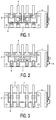
- a rectifier arrangement according to the invention with bond wire connections shown schematically.
- a heat sink 1 On a heat sink 1 is a double-sided metallized (e.g. copper metallization) substrate 2 (e.g. ceramic) applied.
- the heat sink 1 can be designed as a plate in which the heat is brought into contact with a cooling surface is manufactured, or as a finned heatsink, which over air flow is cooled.
- the connection between the substrate 2 and the heat sink 1 is intended with a thermally conductive material. This can e.g. be a solder joint at which reduces air and gas inclusions in the connection through special process control become.
- the bare semiconductor diode chips 3 are on the top of the substrate 2 and directly on the heat sink 1 soldered. They ensure the rectification of the three phases for both Half waves. Also when soldering the diode chips 3 is through special process control ensure that the air and gas inclusions in the solder layer are minimized.
- the heat sink 1 electrically forms the mass of the module.
- the individual stator phases of the three-phase generator and the connector for the battery are on the metallized top of the Tapped substrate 2 or by means of a lead frame.
- the substrate 2 is metallized on both sides laterally with connections 4 for battery and stator phases of the three-phase alternator Mistake.
- the metallization is structured so that it has areas with connections for the Forms semiconductor diode chips 3.
- Bond wire connections 5 for the electrical contacting of the upper chip areas. These are multiple executed to carry the high currents. The entire arrangement can be done by one Frame or a housing are enclosed, so that the semiconductor diode chips 3 through a soft potting can be protected. Alternatively, the structure can be thermoset be encapsulated.
- the rectifier arrangement shown in FIG. 2 corresponds to that in FIG. 1 shown.
- the electrical contacting of the upper semiconductor chip areas 3 takes place here via soldering iron 6. These have the advantage that they draw the current from the semiconductor over a large area take up. This reduces the contact resistance and thus the generation of heat on the semiconductor.
- the placement of the bracket 6 can be done using standard electronics without an additional process such as Wire bonding becomes necessary.
- Substrate 2 has an upper, continuous surface for receiving the semiconductor diode chips 3. These are soldered on as in the other exemplary embodiments.
- the substrate 2 and additional diodes 8 are soldered onto the heat sink 1.
- the diodes 8 are on both Apply soldering pads (e.g. nickel-plated copper) to the sides. This allows one Can solder large diodes in mesa structure technology from both sides without the Danger of creating short circuits.
- the connection between the diodes 3 and 8 is made by individual lead frames 7, which simultaneously make contact for the stator phases form. These lead frames 7 become electrically conductive (e.g. by soldering) on the Diodes 3 and 8 applied. Similar to the embodiment shown in Figure 2 the module can be protected at the end.
Landscapes
- Engineering & Computer Science (AREA)
- Power Engineering (AREA)
- Synchronous Machinery (AREA)
- Rectifiers (AREA)
- Motor Or Generator Cooling System (AREA)
Abstract
Description
- Figur 1:
- eine schematische Darstellung einer Gleichrichteranordnung mit Bonddrahtverbindungen,
- Figur 2:
- eine schematische Darstellung einer Gleichrichteranordnung mit Lotbügeln und
- Figur 3:
- eine schematische Darstellung einer Gleichrichteranordnung mit Stanzgittern.
Claims (1)
- Gleichrichteranordnung für eine Drehstromlichtmaschine eines Kraftfahrzeugesmit einem Kühlkörper (1),mit wenigstens einem auf dem Kühlkörper (1) angeordneten Schaltungsträger (2) mit einer elektrisch leitfähig strukturierten Oberfläche,mit wenigstens einer ersten zur Gleichrichtung einer ersten Halbwelle vorgesehenen, auf der elektrisch leitfähig strukturierten Oberfläche eines Schaltungsträgers (2) angeordneten Diode (3),mit wenigstens einer zweiten zur Gleichrichtung einer zweiten Halbwelle vorgesehenen, auf dem Kühlkörper (1) angeordneten Diode (8).
Applications Claiming Priority (2)
| Application Number | Priority Date | Filing Date | Title |
|---|---|---|---|
| DE19946259A DE19946259A1 (de) | 1999-09-27 | 1999-09-27 | Gleichrichteranordnung |
| DE19946259 | 1999-09-27 |
Publications (2)
| Publication Number | Publication Date |
|---|---|
| EP1089333A2 true EP1089333A2 (de) | 2001-04-04 |
| EP1089333A3 EP1089333A3 (de) | 2001-07-11 |
Family
ID=7923456
Family Applications (1)
| Application Number | Title | Priority Date | Filing Date |
|---|---|---|---|
| EP00203246A Withdrawn EP1089333A3 (de) | 1999-09-27 | 2000-09-19 | Gleichrichteranordnung für eine Drehstromlichtmaschine eines Kraftfahrzeuges |
Country Status (4)
| Country | Link |
|---|---|
| US (1) | US6411536B1 (de) |
| EP (1) | EP1089333A3 (de) |
| JP (1) | JP2001128455A (de) |
| DE (1) | DE19946259A1 (de) |
Families Citing this family (4)
| Publication number | Priority date | Publication date | Assignee | Title |
|---|---|---|---|---|
| DE102004063851B4 (de) | 2004-12-30 | 2020-01-09 | Robert Bosch Gmbh | Verfahren zur Herstellung einer elektronischen Schaltung |
| US7749877B2 (en) * | 2006-03-07 | 2010-07-06 | Siliconix Technology C. V. | Process for forming Schottky rectifier with PtNi silicide Schottky barrier |
| DE102006045293B4 (de) * | 2006-09-26 | 2012-03-29 | Noliac A/S | Festkörperaktor-Antriebsvorrichtung |
| US9312742B2 (en) | 2013-03-01 | 2016-04-12 | Hamilton Sundstrand Corporation | Connector and spring assembly for a generator |
Family Cites Families (7)
| Publication number | Priority date | Publication date | Assignee | Title |
|---|---|---|---|---|
| DE2543196A1 (de) * | 1975-09-27 | 1977-04-07 | Bosch Gmbh Robert | Schleifringlose elektrische maschine |
| JPS5746662A (en) * | 1980-09-04 | 1982-03-17 | Toshiba Corp | Semiconductor rectifier |
| US4538169A (en) * | 1982-11-04 | 1985-08-27 | Motorola, Inc. | Integrated alternator bridge heat sink |
| US4628219A (en) * | 1985-09-13 | 1986-12-09 | Sundstrand Corporation | Rectifier assembly for mounting in a rotor |
| US5731970A (en) * | 1989-12-22 | 1998-03-24 | Hitachi, Ltd. | Power conversion device and semiconductor module suitable for use in the device |
| US5319272A (en) * | 1992-07-14 | 1994-06-07 | Eemco/Datron, Inc. | Miniature rotating rectifier assembly |
| US5892676A (en) * | 1997-10-27 | 1999-04-06 | Hsieh; Joe C. | Rectifier bridges assembly having improved heat dispersing characteristics and an arcing-free design |
-
1999
- 1999-09-27 DE DE19946259A patent/DE19946259A1/de not_active Withdrawn
-
2000
- 2000-09-19 EP EP00203246A patent/EP1089333A3/de not_active Withdrawn
- 2000-09-26 US US09/670,132 patent/US6411536B1/en not_active Expired - Fee Related
- 2000-09-27 JP JP2000294659A patent/JP2001128455A/ja active Pending
Also Published As
| Publication number | Publication date |
|---|---|
| DE19946259A1 (de) | 2001-03-29 |
| US6411536B1 (en) | 2002-06-25 |
| EP1089333A3 (de) | 2001-07-11 |
| JP2001128455A (ja) | 2001-05-11 |
Similar Documents
| Publication | Publication Date | Title |
|---|---|---|
| EP0841843B1 (de) | Leistungsmodul zur Ansteuerung von Elektromotoren | |
| DE60119865T2 (de) | Elektrische Energie(um)wandlungsvorrichtung | |
| DE112007000919B4 (de) | Gemeinsames Gehäuse für eine hohe Leistungsdichte aufweisende Bauteile, insbesondere für IGBTs und Dioden, mit niedriger Induktivität und drahtfreien Bondverbindungen | |
| DE102014113787B4 (de) | Elektronische Vorrichtung und Leistungsvorrichtung mit einer Transistoranordnung mit Halbleiterchips zwischen zwei Substraten und Verfahren zu deren Herstellung | |
| DE102019210172A1 (de) | Halbleitervorrichtung, Leistungswandler, Verfahren zum Herstellen einer Halbleitervorrichtung und Verfahren zum Herstellen eines Leistungswandlers | |
| DE19900603A1 (de) | Elektronisches Halbleitermodul | |
| DE102020126810A1 (de) | Halbleitermodul und Leistungsumwandlungseinrichtung | |
| DE19716113B4 (de) | Elektrische Leistungsstrang-Baugruppe | |
| DE112015003757T5 (de) | Halbleitervorrichtung sowie Generator und Stromrichtvorrichtung, welche die Halbleitervorrichtung verwenden | |
| DE102018205991A1 (de) | Leistungsmodul und Leistungsumrichtervorrichtung | |
| DE102018210721A1 (de) | Semiconductor module, method for manufacturing the same and electric power conversion device | |
| EP0597144A1 (de) | Hybride leistungselektronische Anordnung | |
| DE102022116833B4 (de) | Halbleiterpackage mit niederparasitischer Verbindung zu einer passiven Vorrichtung und Verfahren zum Bestücken einer Halbleiterbaugruppe | |
| DE102018205121A1 (de) | Stromwandlungsvorrichtung | |
| DE112017007960B4 (de) | Halbleitermodul und Leistungsumwandlungsvorrichtung | |
| DE102017222481A1 (de) | Leistungsmodul für Leistungsumwandlungseinrichtung, Leistungsumwandlungseinrichtung und elekktrische Rotationsvorrichtung mit integriertem Steuergerät | |
| DE102023208490B4 (de) | Leistungselektronikmodul und Montageverfahren | |
| DE102015216779A1 (de) | Leistungshalbleitervorrichtung | |
| DE69605149T2 (de) | Gleichrichtereinheit für Wechselstromgenerator | |
| DE112018007231T5 (de) | Halbleiterbauelement und Leistungswandler | |
| DE112021007799T5 (de) | Halbleitermodul und leistungswandler | |
| DE19946259A1 (de) | Gleichrichteranordnung | |
| DE102022126046B4 (de) | Halbleitervorrichtung und Leistungsumwandlungsvorrichtung | |
| DE102022213007B4 (de) | Leistungsmodul für einen Wandler mit abschirmungsoptimierten Signalpins, Wandler, elektrischer Achsantrieb sowie Fahrzeug | |
| EP3399549A1 (de) | Halbleitermodul |
Legal Events
| Date | Code | Title | Description |
|---|---|---|---|
| PUAI | Public reference made under article 153(3) epc to a published international application that has entered the european phase |
Free format text: ORIGINAL CODE: 0009012 |
|
| AK | Designated contracting states |
Kind code of ref document: A2 Designated state(s): DE FR GB |
|
| AX | Request for extension of the european patent |
Free format text: AL;LT;LV;MK;RO;SI |
|
| PUAL | Search report despatched |
Free format text: ORIGINAL CODE: 0009013 |
|
| AK | Designated contracting states |
Kind code of ref document: A3 Designated state(s): AT BE CH CY DE DK ES FI FR GB GR IE IT LI LU MC NL PT SE |
|
| AX | Request for extension of the european patent |
Free format text: AL;LT;LV;MK;RO;SI |
|
| RIC1 | Information provided on ipc code assigned before grant |
Free format text: 7H 01L 25/11 A, 7H 01L 23/367 B, 7H 02K 11/04 B |
|
| 17P | Request for examination filed |
Effective date: 20020111 |
|
| AKX | Designation fees paid |
Free format text: DE FR GB |
|
| RAP1 | Party data changed (applicant data changed or rights of an application transferred) |
Owner name: PHILIPS CORPORATE INTELLECTUAL PROPERTY GMBH Owner name: KONINKLIJKE PHILIPS ELECTRONICS N.V. |
|
| RAP1 | Party data changed (applicant data changed or rights of an application transferred) |
Owner name: INTERNATIONAL RECTIFIER CORPORATION |
|
| 17Q | First examination report despatched |
Effective date: 20060808 |
|
| STAA | Information on the status of an ep patent application or granted ep patent |
Free format text: STATUS: THE APPLICATION IS DEEMED TO BE WITHDRAWN |
|
| 18D | Application deemed to be withdrawn |
Effective date: 20090616 |