EP1089321A1 - Ceramic arc tube - Google Patents
Ceramic arc tube Download PDFInfo
- Publication number
- EP1089321A1 EP1089321A1 EP00119008A EP00119008A EP1089321A1 EP 1089321 A1 EP1089321 A1 EP 1089321A1 EP 00119008 A EP00119008 A EP 00119008A EP 00119008 A EP00119008 A EP 00119008A EP 1089321 A1 EP1089321 A1 EP 1089321A1
- Authority
- EP
- European Patent Office
- Prior art keywords
- arc tube
- ceramic
- sections
- ceramic arc
- lap joint
- Prior art date
- Legal status (The legal status is an assumption and is not a legal conclusion. Google has not performed a legal analysis and makes no representation as to the accuracy of the status listed.)
- Withdrawn
Links
- 239000000919 ceramic Substances 0.000 title claims abstract description 26
- 238000007789 sealing Methods 0.000 claims description 36
- 239000000463 material Substances 0.000 claims description 5
- 238000000034 method Methods 0.000 abstract description 7
- 238000005245 sintering Methods 0.000 description 7
- 238000005266 casting Methods 0.000 description 6
- 239000011162 core material Substances 0.000 description 6
- 238000005260 corrosion Methods 0.000 description 4
- 230000007797 corrosion Effects 0.000 description 4
- 239000011230 binding agent Substances 0.000 description 3
- 239000007789 gas Substances 0.000 description 3
- 238000002844 melting Methods 0.000 description 3
- 230000008018 melting Effects 0.000 description 3
- UFHFLCQGNIYNRP-UHFFFAOYSA-N Hydrogen Chemical compound [H][H] UFHFLCQGNIYNRP-UHFFFAOYSA-N 0.000 description 2
- PNEYBMLMFCGWSK-UHFFFAOYSA-N aluminium oxide Inorganic materials [O-2].[O-2].[O-2].[Al+3].[Al+3] PNEYBMLMFCGWSK-UHFFFAOYSA-N 0.000 description 2
- 230000015572 biosynthetic process Effects 0.000 description 2
- 238000000071 blow moulding Methods 0.000 description 2
- 238000010276 construction Methods 0.000 description 2
- 239000001257 hydrogen Substances 0.000 description 2
- 229910052739 hydrogen Inorganic materials 0.000 description 2
- 238000005304 joining Methods 0.000 description 2
- 238000004519 manufacturing process Methods 0.000 description 2
- 229910001507 metal halide Inorganic materials 0.000 description 2
- 150000005309 metal halides Chemical class 0.000 description 2
- 239000000203 mixture Substances 0.000 description 2
- 238000007664 blowing Methods 0.000 description 1
- 238000009833 condensation Methods 0.000 description 1
- 230000005494 condensation Effects 0.000 description 1
- 238000001816 cooling Methods 0.000 description 1
- 238000011161 development Methods 0.000 description 1
- 230000018109 developmental process Effects 0.000 description 1
- 238000009792 diffusion process Methods 0.000 description 1
- 230000000694 effects Effects 0.000 description 1
- 239000011521 glass Substances 0.000 description 1
- 238000010438 heat treatment Methods 0.000 description 1
- 238000001746 injection moulding Methods 0.000 description 1
- 238000000462 isostatic pressing Methods 0.000 description 1
- 230000007774 longterm Effects 0.000 description 1
- 230000013011 mating Effects 0.000 description 1
- 238000012986 modification Methods 0.000 description 1
- 230000004048 modification Effects 0.000 description 1
- 238000000465 moulding Methods 0.000 description 1
- 239000011368 organic material Substances 0.000 description 1
- 230000035515 penetration Effects 0.000 description 1
- 238000007569 slipcasting Methods 0.000 description 1
Images


Classifications
-
- H—ELECTRICITY
- H01—ELECTRIC ELEMENTS
- H01J—ELECTRIC DISCHARGE TUBES OR DISCHARGE LAMPS
- H01J61/00—Gas-discharge or vapour-discharge lamps
- H01J61/02—Details
- H01J61/36—Seals between parts of vessels; Seals for leading-in conductors; Leading-in conductors
- H01J61/361—Seals between parts of vessel
-
- H—ELECTRICITY
- H01—ELECTRIC ELEMENTS
- H01J—ELECTRIC DISCHARGE TUBES OR DISCHARGE LAMPS
- H01J61/00—Gas-discharge or vapour-discharge lamps
- H01J61/02—Details
- H01J61/36—Seals between parts of vessels; Seals for leading-in conductors; Leading-in conductors
- H01J61/361—Seals between parts of vessel
- H01J61/365—Annular seals disposed between the ends of the vessel
Definitions
- This invention relates to ceramic arc tubes for high intensity discharge lamps.
- this invention relates to forming hermetic seals in ceramic arc tubes.
- Ceramic arc tubes are used to contain the high temperature arcs of high intensity discharge (HID) lamps.
- HID high intensity discharge
- General examples of ceramic arc tubes for HID lighting applications are shown in U.S. Patent Nos. 4,387,067, 4,999,145, and 4,799,601 which are incorporated herein by reference.
- these arc tubes were long cylindrical tubes, but recent lamp developments and the use of corrosive metal halide fill materials have dictated the use of more compact and complex shapes. For example, when a cylindrical geometry is used with a metal halide fill, the lamp fill tends to reside at the ends of the arc tube in the corner between the tube wall and the end button. During long term operation, these lamps are often characterized by corrosion of the ceramic in this area.
- the lamp ultimately fails when the corrosion breaches the arc tube wall allowing the fill gas to leak.
- Modifying the arc tube geometry to have hemispherical ends reduces the arc tube corrosion by eliminating the cold spot where the fill condenses. Not unexpectedly, the compact and complex arc tube shapes are more difficult to manufacture.
- greater effort is required to keep the parts aligned and obtain hermetic seals.
- Blow molding and gel casting can be used to form unitary arc tube bodies having the desired internal geometry but both methods have inherent disadvantages.
- Blow molded lamps are limited by the degree of expansion achievable during blowing and are characterized by a thinning of the arc tube wall.
- Gel casting is limited by the need to use a temporary core to define the cavity shape. The temporary core becomes entrapped inside the formed arc tube and must be removed. Typically, this is achieved by melting the core which is made of a low melting point material such as a wax. Because the core is destroyed by this process, gel casting tends to be a more expensive process. Additionally, the temporary core material can contaminate the arc tube cavity causing problems with lamp operation.
- a ceramic arc tube comprising a hollow ceramic body having a wall, electrodes, male and female sections, and a cavity containing a fill material; the electrodes extending into the cavity through the wall and being connectable to an external source of electrical power; the male section being sealed hermetically to the female section by a lap joint; the lap joint having internal and external positioning interfaces and a sealing interface.
- a ceramic arc tube assembly comprising male and female arc tube sections; each section being substantially hollow and having a wall and open and closed ends; the open ends having a sealing surface and internal and external positioning surfaces, the internal and external positioning surfaces being located at opposite ends of the sealing surface; the closed ends having an opening for receiving an electrode; the male and female sections when joined at the open ends forming a lap joint and enclosing a cavity.
- the present invention uses a two piece arc tube design requiring only one hermetic joint.
- the arc tube is made in two sections and joined using a lap joint. Because the arc tube body is made in two sections, each section can be produced by conventional ceramic forming techniques such as isostatic pressing, injection molding, slip casting, or gel casting. If gel casting is used, a temporary core is not needed to form the internal contours of the arc tube because each section has an accessible open end.
- the lap joint is designed so that the two sections may be easily aligned and fitted together. Overlapping flanges are created on the open ends of each section. The flanges provide present surfaces for sealing and positioning the two sections. To maintain a tight seal, the sections may be designed with a slight interference fit. The amount of interference fit required to maintain a tight seal is typically 1 to 8%. Greater degrees of interference fit could be used but might lead to considerable distortion of the arc tube shape.
- any organic binder in the green parts is removed.
- the assembled sections are presintered to tack bond them together and remove residual organic material.
- An alternative method of joining the two sections is to combine a temperature slightly above the softening or melting point of the organic binders used in the fabrication of the sections with a slight pressure to weld the two sections together prior to binder removal. In this manner, the degree of interference fit could be reduced or eliminated thereby reducing distortion of the sintered arc tube.
- the final sealing of the two sections is achieved by sintering the arc tube usually in a hydrogen containing atmosphere. The temperatures, heating rate, cooling rate and soak period at peak temperature will vary depending on the ceramic composition.
- Various arc tube and lap joint configurations are shown in Figs. 1-6.
- Fig. 1 is a cross sectional view of an arc tube assembly having substantially hollow, cylindrical male 4 and female 2 sections. Each section has the same inside and outside diameters. At the closed end 11 of each section, there is an opening 12 in the wall 14 for inserting an electrode (not shown). Capillaries 30 are attached at the closed ends 11 to facilitate positioning and sealing of the electrode in the completed arc tube. At open ends 15 and 17, the sections have internal 10 and external 8 positioning surfaces and sealing surfaces 3 and 6. These surfaces conjoin to form the lap joint shown in Fig. 2. More particularly, flange 5 of male section 4 extends coaxially at the periphery of open end 17. The outside diameter of flange 5 is less than the outside diameter of the male section.
- Sealing surface 3 is cylindrical and is formed by the outside diameter of flange 5.
- flange 7 of female section 2 extends coaxially at the periphery of open end 15.
- Flange 7 has an inside diameter which is greater than the inside diameter of female section 2 and equal to the outside diameter of flange 5.
- Sealing surface 6 is cylindrical and is formed by the inside diameter of flange 7.
- the recess formed at the open end 15 accepts flange 5 of the male section when the parts are mated to form the arc tube.
- Positioning surfaces 8 and 10 are formed by the discontinuities in the diameters of each section 2 and 4 at their open ends. Positioning surfaces 8 and 10 ensure proper mating of the two sections. Preferably, positioning surfaces 8 and 10 are substantially orthogonal to the central axis of sections 2 and 4 however other configurations are possible.
- sealing surfaces 3 and 6 are cylindrical and coaxial with the central axis of the two sections.
- one or both of the sealing surfaces may be slightly tapered.
- the outside diameter of flange 5 is made slightly larger than the inside diameter of flange 7 and sealing surface 3 of male section 4 is tapered inwardly.
- Hermetic seals have been obtained using a 1% interference fit (0.004 inches) and a 2° taper on the male flange. Similar performance was observed when the interference fit cut in half to 0.002 inches.
- the arc tube sections are made preferably from alumina which provides the necessary degree of translucency after sintering.
- a preferred composition is a pure alumina containing about 500 ppm MgO.
- the assembled sections are presintered in air at below 1350°C, and preferably at 1200°C for 1 hour. Final sintering is performed in a hydrogen containing atmosphere at a temperature from about 1820°C to 1950°C. More preferably, the arc tube parts are sintered in wet H 2 at 1935°C for 4 hours.
- the sintered arc tubes of the present invention exhibit excellent dimensional control and reproducibility.
- Fig. 2 is a cross sectional view of an assembled arc tube having the configuration shown in Fig. 1.
- Male section 4 has been mated to female section 2 and sintered to form a hermetic seal at lap joint 25.
- Lap joint 25 is composed of sealing interface 28 and positioning interfaces 22 and 24.
- the sealing and positioning interfaces in the assembled arc tube are formed at the junction of the sealing and positioning surfaces shown in Fig. 1.
- a hermetic seal is formed at the sealing interface 28 after final sintering.
- the general placement of sealing interface 28 is midway through arc tube wall 14. However, the relative thickness of flanges 5 and 7 may be adjusted to effect the formation of the sealing interface at different depths in wall 14.
- the width of sealing interface 28 be at least equal to half the thickness of the wall 14 in the region immediately adjacent to the lap joint.
- Hermetic seals may also be formed at the positioning interfaces 22 and 24. However, depending on the lap joint configuration, gaps may form at the positioning interfaces after sintering. In this embodiment, these gaps may extend up to halfway through the arc tube wall but have not been shown to affect lamp performance. The interior gap can be eliminated by making the male flange 0.001 to 0.005 inches longer than the female flange.
- Electrodes 20 are sealed hermetically into capillaries 30 by a glass frit.
- the electrodes extend into cavity 32 and are connectable to an external source of electrical power such as a ballast.
- the cavity 32 contains fill 35 and a fill gas (not shown).
- the fill 32 may consist of any number of known arc tube fill materials and fill gases.
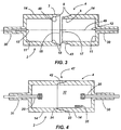
- Fig. 3 and 4 are cross sectional views of an arc tube assembly and resultant arc tube similar to those shown in Figs. 1 and 2.
- Flanges 5 and 7 are tapered with respect to central axis 49 to give sealing surfaces 40 and 43 and sealing interface 42 a frustoconical shape.
- the taper angle formed by frustoconical sealing surfaces 40 and 43 and central axis 49 may varied from 5 to 20 degrees. The limit on the taper angle is the angle beyond which a good diffusion bond seal can be achieved. If the angle is too steep, the driving force for bonding using an interference seal would be reduced to a point where sections 2 and 4 would separate during sealing by sliding along the sealing interface 42 instead of joining.
- the frustoconical shape can provide a wider sealing interface than the cylindrical shape and tends to reduce the formation and penetration of gaps at positioning interfaces 22 and 24. This is believed to increase the strength of the lap joint 47.
- Fig. 5 and 6 illustrates an embodiment of the present invention in which the arc tube shape is not a right cylinder but still remains axially symmetric about central axis 49.
- closed ends 11 have a rounded, hemispherical geometry.
- the rounded contour reduces corrosion of the arc tube wall caused by the condensation of fill 35.
- Lap joint 47 is the same as the lap joint shown in Figs. 3 and 4.
Landscapes
- Vessels And Coating Films For Discharge Lamps (AREA)
Abstract
Description
- This invention relates to ceramic arc tubes for high intensity discharge lamps. In particular, this invention relates to forming hermetic seals in ceramic arc tubes.
- Ceramic arc tubes are used to contain the high temperature arcs of high intensity discharge (HID) lamps. General examples of ceramic arc tubes for HID lighting applications are shown in U.S. Patent Nos. 4,387,067, 4,999,145, and 4,799,601 which are incorporated herein by reference. Historically, these arc tubes were long cylindrical tubes, but recent lamp developments and the use of corrosive metal halide fill materials have dictated the use of more compact and complex shapes. For example, when a cylindrical geometry is used with a metal halide fill, the lamp fill tends to reside at the ends of the arc tube in the corner between the tube wall and the end button. During long term operation, these lamps are often characterized by corrosion of the ceramic in this area. The lamp ultimately fails when the corrosion breaches the arc tube wall allowing the fill gas to leak. Modifying the arc tube geometry to have hemispherical ends reduces the arc tube corrosion by eliminating the cold spot where the fill condenses. Not unexpectedly, the compact and complex arc tube shapes are more difficult to manufacture. In addition, if several parts are used in the arc tube assembly, greater effort is required to keep the parts aligned and obtain hermetic seals. Thus, it is also desirable to reduce number of parts and seals used to construct the arc tube.
- Blow molding and gel casting can be used to form unitary arc tube bodies having the desired internal geometry but both methods have inherent disadvantages. Blow molded lamps are limited by the degree of expansion achievable during blowing and are characterized by a thinning of the arc tube wall. Gel casting is limited by the need to use a temporary core to define the cavity shape. The temporary core becomes entrapped inside the formed arc tube and must be removed. Typically, this is achieved by melting the core which is made of a low melting point material such as a wax. Because the core is destroyed by this process, gel casting tends to be a more expensive process. Additionally, the temporary core material can contaminate the arc tube cavity causing problems with lamp operation.
- While it is possible to form a unitary arc tube body by blow molding or gel casting, current designs further require that two capillaries which contain and seal the electrodes be joined to the arc tube by interference sintering. This results in a three piece arc tube construction having two joints that must be hermetic after sintering.
- It is an object of the invention to obviate the disadvantages of the prior art.
- It is another object of the invention to provide a ceramic arc tube having a two piece construction.
- It is a further object of the invention to provide a ceramic arc tube assembly which can be formed by conventional ceramic molding techniques.
- In accordance with one aspect the invention, there is provided a ceramic arc tube comprising a hollow ceramic body having a wall, electrodes, male and female sections, and a cavity containing a fill material; the electrodes extending into the cavity through the wall and being connectable to an external source of electrical power; the male section being sealed hermetically to the female section by a lap joint; the lap joint having internal and external positioning interfaces and a sealing interface.
- In accordance with another aspect of the invention, there is provided a ceramic arc tube assembly comprising male and female arc tube sections; each section being substantially hollow and having a wall and open and closed ends; the open ends having a sealing surface and internal and external positioning surfaces, the internal and external positioning surfaces being located at opposite ends of the sealing surface; the closed ends having an opening for receiving an electrode; the male and female sections when joined at the open ends forming a lap joint and enclosing a cavity.
-
- Fig 1. is a cross sectional view of a cylindrical arc tube assembly having cylindrical sealing surfaces.
- Fig. 2 is a cross sectional view of an assembled arc tube having the configuration shown in Fig. 1.
- Fig. 3 is a cross sectional view of a cylindrical arc tube assembly having frustoconical sealing surfaces.
- Fig. 4 is a cross sectional view of an assembled arc tube having the configuration shown in Fig. 3.
- Fig. 5 is a cross sectional view of another axially symmetric arc tube having frustoconical sealing surfaces.
- Fig. 6 is a cross sectional view of an assembled arc tube having the configuration shown in Fig. 5.
-
- For a better understanding of the present invention, together with other and further objects, advantages and capabilities thereof, reference is made to the following disclosure and appended claims taken in conjunction with the above-described drawings.
- The present invention uses a two piece arc tube design requiring only one hermetic joint. The arc tube is made in two sections and joined using a lap joint. Because the arc tube body is made in two sections, each section can be produced by conventional ceramic forming techniques such as isostatic pressing, injection molding, slip casting, or gel casting. If gel casting is used, a temporary core is not needed to form the internal contours of the arc tube because each section has an accessible open end. The lap joint is designed so that the two sections may be easily aligned and fitted together. Overlapping flanges are created on the open ends of each section. The flanges provide present surfaces for sealing and positioning the two sections. To maintain a tight seal, the sections may be designed with a slight interference fit. The amount of interference fit required to maintain a tight seal is typically 1 to 8%. Greater degrees of interference fit could be used but might lead to considerable distortion of the arc tube shape.
- After the parts are formed and assembled, any organic binder in the green parts is removed. The assembled sections are presintered to tack bond them together and remove residual organic material. An alternative method of joining the two sections is to combine a temperature slightly above the softening or melting point of the organic binders used in the fabrication of the sections with a slight pressure to weld the two sections together prior to binder removal. In this manner, the degree of interference fit could be reduced or eliminated thereby reducing distortion of the sintered arc tube. The final sealing of the two sections is achieved by sintering the arc tube usually in a hydrogen containing atmosphere. The temperatures, heating rate, cooling rate and soak period at peak temperature will vary depending on the ceramic composition. Various arc tube and lap joint configurations are shown in Figs. 1-6.
- Fig. 1 is a cross sectional view of an arc tube assembly having substantially hollow,
cylindrical male 4 and female 2 sections. Each section has the same inside and outside diameters. At the closedend 11 of each section, there is anopening 12 in thewall 14 for inserting an electrode (not shown).Capillaries 30 are attached at the closedends 11 to facilitate positioning and sealing of the electrode in the completed arc tube. Atopen ends surfaces flange 5 ofmale section 4 extends coaxially at the periphery ofopen end 17. The outside diameter offlange 5 is less than the outside diameter of the male section.Sealing surface 3 is cylindrical and is formed by the outside diameter offlange 5. Similarly,flange 7 offemale section 2 extends coaxially at the periphery ofopen end 15.Flange 7 has an inside diameter which is greater than the inside diameter offemale section 2 and equal to the outside diameter offlange 5. Sealingsurface 6 is cylindrical and is formed by the inside diameter offlange 7. The recess formed at theopen end 15 acceptsflange 5 of the male section when the parts are mated to form the arc tube. Positioning surfaces 8 and 10 are formed by the discontinuities in the diameters of eachsection positioning surfaces sections - In the embodiment shown in Fig. 1, sealing
surfaces flange 5 is made slightly larger than the inside diameter offlange 7 and sealingsurface 3 ofmale section 4 is tapered inwardly. Hermetic seals have been obtained using a 1% interference fit (0.004 inches) and a 2° taper on the male flange. Similar performance was observed when the interference fit cut in half to 0.002 inches. - The arc tube sections are made preferably from alumina which provides the necessary degree of translucency after sintering. A preferred composition is a pure alumina containing about 500 ppm MgO. After forming and assembling the parts, the assembled sections are presintered in air at below 1350°C, and preferably at 1200°C for 1 hour. Final sintering is performed in a hydrogen containing atmosphere at a temperature from about 1820°C to 1950°C. More preferably, the arc tube parts are sintered in wet H2 at 1935°C for 4 hours. In addition to forming hermetic seals, the sintered arc tubes of the present invention exhibit excellent dimensional control and reproducibility.
- Fig. 2 is a cross sectional view of an assembled arc tube having the configuration shown in Fig. 1.
Male section 4 has been mated tofemale section 2 and sintered to form a hermetic seal at lap joint 25. Lap joint 25 is composed of sealinginterface 28 andpositioning interfaces interface 28 after final sintering. The general placement of sealinginterface 28 is midway througharc tube wall 14. However, the relative thickness offlanges wall 14. It is preferred that the width of sealinginterface 28 be at least equal to half the thickness of thewall 14 in the region immediately adjacent to the lap joint. Hermetic seals may also be formed at the positioning interfaces 22 and 24. However, depending on the lap joint configuration, gaps may form at the positioning interfaces after sintering. In this embodiment, these gaps may extend up to halfway through the arc tube wall but have not been shown to affect lamp performance. The interior gap can be eliminated by making the male flange 0.001 to 0.005 inches longer than the female flange. -
Electrodes 20 are sealed hermetically intocapillaries 30 by a glass frit. The electrodes extend intocavity 32 and are connectable to an external source of electrical power such as a ballast. Thecavity 32 containsfill 35 and a fill gas (not shown). Thefill 32 may consist of any number of known arc tube fill materials and fill gases. - Fig. 3 and 4 are cross sectional views of an arc tube assembly and resultant arc tube similar to those shown in Figs. 1 and 2.
Flanges central axis 49 to give sealingsurfaces central axis 49 may varied from 5 to 20 degrees. The limit on the taper angle is the angle beyond which a good diffusion bond seal can be achieved. If the angle is too steep, the driving force for bonding using an interference seal would be reduced to a point wheresections interface 42 instead of joining. The frustoconical shape can provide a wider sealing interface than the cylindrical shape and tends to reduce the formation and penetration of gaps atpositioning interfaces - Fig. 5 and 6 illustrates an embodiment of the present invention in which the arc tube shape is not a right cylinder but still remains axially symmetric about
central axis 49. In this embodiment, closed ends 11 have a rounded, hemispherical geometry. As previously explained, the rounded contour reduces corrosion of the arc tube wall caused by the condensation offill 35. Lap joint 47 is the same as the lap joint shown in Figs. 3 and 4. - While there has been shown and described what are at the present considered the preferred embodiments of the invention, it will be obvious to those skilled in the art that various changes and modifications may be made therein without departing from the scope of the invention as defined by the appended claims.
Claims (8)
- A ceramic arc tube comprising:a hollow ceramic body having a wall, electrodes, male and female sections, and a cavity containing a fill material; the electrodes extending into the cavity through the wall and being connectable to an external source of electrical power; the male section being sealed hermetically to the female section by a lap joint; the lap joint having internal and external positioning interfaces and a sealing interface.
- The ceramic arc tube of claim 1 wherein the ceramic body and sealing interface are symmetric about a central axis.
- The ceramic arc tube of claim 2 wherein the sealing interface is frustoconical.
- The ceramic arc tube of claim 3 wherein the sealing interface is cylindrical.
- The ceramic arc tube of claim 2 wherein the internal and external positioning interfaces are orthogonal to the central axis.
- The ceramic arc tube of claim 3 wherein the sealing interface has a taper angle of between 5 and 20 degrees.
- The ceramic arc tube of claim 1 wherein the width of the sealing interface is at least equal to half of the thickness of the arc tube wall in a region immediately adjacent the lap joint.
- A ceramic arc tube assembly comprising: male and female arc tube sections; each section being substantially hollow and having a wall and open and closed ends; the open ends having a sealing surface and internal and external positioning surfaces, the internal and external positioning surfaces being located at opposite ends of the sealing surface; the closed ends having an opening for receiving an electrode; the male and female sections when joined at the open ends forming a lap joint and enclosing a cavity.
Applications Claiming Priority (2)
| Application Number | Priority Date | Filing Date | Title |
|---|---|---|---|
| US40881299A | 1999-09-29 | 1999-09-29 | |
| US408812 | 1999-09-29 |
Publications (1)
| Publication Number | Publication Date |
|---|---|
| EP1089321A1 true EP1089321A1 (en) | 2001-04-04 |
Family
ID=23617874
Family Applications (1)
| Application Number | Title | Priority Date | Filing Date |
|---|---|---|---|
| EP00119008A Withdrawn EP1089321A1 (en) | 1999-09-29 | 2000-09-01 | Ceramic arc tube |
Country Status (4)
| Country | Link |
|---|---|
| EP (1) | EP1089321A1 (en) |
| JP (1) | JP4709361B2 (en) |
| CA (1) | CA2316649A1 (en) |
| HU (1) | HUP0003776A3 (en) |
Cited By (12)
| Publication number | Priority date | Publication date | Assignee | Title |
|---|---|---|---|---|
| US6724144B2 (en) | 2000-03-21 | 2004-04-20 | Japan Storage Battery Co., Ltd. | Discharge lamp |
| DE102004001176A1 (en) * | 2004-01-05 | 2005-08-04 | Schott Ag | Technical system including at least one structural group and/or component from at least two individual parts which can be subjected to high mechanical loads and/or high temperatures up to 1100degreesC |
| WO2007078574A1 (en) * | 2005-12-19 | 2007-07-12 | General Electric Company | Ceramic arc chamber having shaped ends |
| WO2006054237A3 (en) * | 2004-11-19 | 2008-04-17 | Koninkl Philips Electronics Nv | High-pressure discharge lamp |
| DE102007006180A1 (en) | 2007-02-07 | 2008-08-14 | Patent-Treuhand-Gesellschaft für elektrische Glühlampen mbH | Method for producing a ceramic discharge vessel and associated high-pressure discharge lamp |
| DE102008063620A1 (en) * | 2008-12-18 | 2010-06-24 | Osram Gesellschaft mit beschränkter Haftung | Ceramic discharge vessel for a high-pressure discharge lamp |
| WO2009139978A3 (en) * | 2008-05-15 | 2010-09-16 | Osram Sylvania, Inc. | Ceramic discharge lamp with integral burner and reflector |
| CN101353263B (en) * | 2007-07-26 | 2010-09-29 | 余恺为 | Integrated ceramic metallic halogen lamp electric arc pipe shell gel cementing manufacturing method |
| EP2323156A3 (en) * | 2009-11-13 | 2011-06-01 | NGK Insulators, Ltd. | Ceramic tube for high-intensity discharge lamp and method of producing the same |
| WO2012113659A1 (en) | 2011-02-22 | 2012-08-30 | Osram Ag | Ceramic discharge vessel and related lamp and method of manufacturing such a vessel |
| US8398796B2 (en) | 2007-11-20 | 2013-03-19 | General Electric Company | Green joining ceramics |
| CN116250841A (en) * | 2023-02-27 | 2023-06-13 | 中北大学 | An electrocardiographic electrode and an electrocardiographic monitoring system for reducing motion noise |
Families Citing this family (7)
| Publication number | Priority date | Publication date | Assignee | Title |
|---|---|---|---|---|
| US6798139B2 (en) * | 2002-06-25 | 2004-09-28 | General Electric Company | Three electrode ceramic metal halide lamp |
| JP2011090001A (en) * | 2005-04-26 | 2011-05-06 | Seiko Instruments Inc | Method of manufacturing near-field light generation element |
| JP4787557B2 (en) * | 2005-04-26 | 2011-10-05 | セイコーインスツル株式会社 | Manufacturing method of near-field light generating element |
| JP5798853B2 (en) * | 2006-01-16 | 2015-10-21 | セイコーインスツル株式会社 | Manufacturing method of near-field light generating element |
| WO2007111380A1 (en) | 2006-03-24 | 2007-10-04 | Ngk Insulators, Ltd. | Method for producing sintered body, and sintered body |
| KR100866502B1 (en) * | 2007-05-08 | 2008-11-03 | 주식회사 기노리 | Ceramic tube having spiral coupling part for high pressure discharge lamp and manufacturing method thereof |
| CN103151238A (en) * | 2011-12-07 | 2013-06-12 | 宁波光令材料科技有限公司 | Ceramic electric arc lamp tube and manufacturing method thereof |
Citations (4)
| Publication number | Priority date | Publication date | Assignee | Title |
|---|---|---|---|---|
| NL7415840A (en) * | 1974-12-05 | 1976-06-09 | Philips Nv | High pressure discharge tube for lamp with narrow ends - has mould with flexible polyurethane outer jacket and polycrystalline wall structure |
| US4387067A (en) * | 1980-02-06 | 1983-06-07 | Ngk Insulators, Ltd. | Ceramic arc tube of metal vapor discharge lamps and a method of producing the same |
| EP0331154A1 (en) * | 1988-03-03 | 1989-09-06 | Feldmühle Aktiengesellschaft | Tube provided with an enlarged portion for metal vapour discharge lamps |
| JPH1064481A (en) * | 1996-08-20 | 1998-03-06 | Kyocera Corp | Ceramic tube for discharge lamp and method of manufacturing the same |
Family Cites Families (7)
| Publication number | Priority date | Publication date | Assignee | Title |
|---|---|---|---|---|
| JPS5280675A (en) * | 1975-12-26 | 1977-07-06 | Toshiba Corp | Metal vapor discharge lamp |
| JPS6264046A (en) * | 1985-09-17 | 1987-03-20 | Toshiba Corp | Manufacture of ceramic discharge lamp |
| JPS6484564A (en) * | 1987-09-25 | 1989-03-29 | Kyoritsu Denki Kk | Extra-high pressure discharge lamp |
| JP2869097B2 (en) * | 1989-09-28 | 1999-03-10 | 岩城硝子株式会社 | Lamp with multilayer reflector |
| JPH08273616A (en) * | 1995-03-31 | 1996-10-18 | Toto Ltd | Sealing part structure of aperture part of metal vapor light emitting tube |
| JPH10134768A (en) * | 1996-10-25 | 1998-05-22 | Toto Ltd | Discharge lamp |
| TW478006B (en) * | 1999-12-23 | 2002-03-01 | Gen Electric | Single ended ceramic arc discharge lamp and method of making same |
-
2000
- 2000-08-24 CA CA002316649A patent/CA2316649A1/en not_active Abandoned
- 2000-09-01 EP EP00119008A patent/EP1089321A1/en not_active Withdrawn
- 2000-09-26 JP JP2000292409A patent/JP4709361B2/en not_active Expired - Fee Related
- 2000-09-27 HU HU0003776A patent/HUP0003776A3/en unknown
Patent Citations (4)
| Publication number | Priority date | Publication date | Assignee | Title |
|---|---|---|---|---|
| NL7415840A (en) * | 1974-12-05 | 1976-06-09 | Philips Nv | High pressure discharge tube for lamp with narrow ends - has mould with flexible polyurethane outer jacket and polycrystalline wall structure |
| US4387067A (en) * | 1980-02-06 | 1983-06-07 | Ngk Insulators, Ltd. | Ceramic arc tube of metal vapor discharge lamps and a method of producing the same |
| EP0331154A1 (en) * | 1988-03-03 | 1989-09-06 | Feldmühle Aktiengesellschaft | Tube provided with an enlarged portion for metal vapour discharge lamps |
| JPH1064481A (en) * | 1996-08-20 | 1998-03-06 | Kyocera Corp | Ceramic tube for discharge lamp and method of manufacturing the same |
Cited By (18)
| Publication number | Priority date | Publication date | Assignee | Title |
|---|---|---|---|---|
| US6724144B2 (en) | 2000-03-21 | 2004-04-20 | Japan Storage Battery Co., Ltd. | Discharge lamp |
| DE102004001176A1 (en) * | 2004-01-05 | 2005-08-04 | Schott Ag | Technical system including at least one structural group and/or component from at least two individual parts which can be subjected to high mechanical loads and/or high temperatures up to 1100degreesC |
| WO2006054237A3 (en) * | 2004-11-19 | 2008-04-17 | Koninkl Philips Electronics Nv | High-pressure discharge lamp |
| WO2007078574A1 (en) * | 2005-12-19 | 2007-07-12 | General Electric Company | Ceramic arc chamber having shaped ends |
| DE102007006180A1 (en) | 2007-02-07 | 2008-08-14 | Patent-Treuhand-Gesellschaft für elektrische Glühlampen mbH | Method for producing a ceramic discharge vessel and associated high-pressure discharge lamp |
| WO2008095771A3 (en) * | 2007-02-07 | 2008-11-13 | Osram Gmbh | Method for producing a ceramic discharge vessel and corresponding high pressure discharge lamp |
| CN101353263B (en) * | 2007-07-26 | 2010-09-29 | 余恺为 | Integrated ceramic metallic halogen lamp electric arc pipe shell gel cementing manufacturing method |
| US8398796B2 (en) | 2007-11-20 | 2013-03-19 | General Electric Company | Green joining ceramics |
| WO2009139978A3 (en) * | 2008-05-15 | 2010-09-16 | Osram Sylvania, Inc. | Ceramic discharge lamp with integral burner and reflector |
| US8247972B2 (en) | 2008-05-15 | 2012-08-21 | Osram Sylvania Inc. | Ceramic discharge lamp with integral burner and reflector |
| DE102008063620A1 (en) * | 2008-12-18 | 2010-06-24 | Osram Gesellschaft mit beschränkter Haftung | Ceramic discharge vessel for a high-pressure discharge lamp |
| EP2323156A3 (en) * | 2009-11-13 | 2011-06-01 | NGK Insulators, Ltd. | Ceramic tube for high-intensity discharge lamp and method of producing the same |
| US8420932B2 (en) | 2009-11-13 | 2013-04-16 | Ngk Insulators, Ltd. | Ceramic tube for high-intensity discharge lamp and method of producing the same |
| WO2012113659A1 (en) | 2011-02-22 | 2012-08-30 | Osram Ag | Ceramic discharge vessel and related lamp and method of manufacturing such a vessel |
| DE112012000355T5 (en) | 2011-02-22 | 2013-10-17 | Osram Gmbh | Ceramic discharge vessel and corresponding lamp and method for producing such a vessel |
| US9218950B2 (en) | 2011-02-22 | 2015-12-22 | Osram Gmbh | Ceramic discharge vessel and related lamp and method of manufacturing such a vessel |
| CN116250841A (en) * | 2023-02-27 | 2023-06-13 | 中北大学 | An electrocardiographic electrode and an electrocardiographic monitoring system for reducing motion noise |
| CN116250841B (en) * | 2023-02-27 | 2025-04-25 | 中北大学 | An electrocardiogram electrode and an electrocardiogram monitoring system for reducing motion noise |
Also Published As
| Publication number | Publication date |
|---|---|
| HUP0003776A2 (en) | 2002-01-28 |
| CA2316649A1 (en) | 2001-03-29 |
| JP4709361B2 (en) | 2011-06-22 |
| JP2001118543A (en) | 2001-04-27 |
| HUP0003776A3 (en) | 2002-12-28 |
Similar Documents
| Publication | Publication Date | Title |
|---|---|---|
| CA2316649A1 (en) | Ceramic arc tube | |
| JP3465193B2 (en) | High pressure discharge lamp | |
| US6274982B1 (en) | Monolithic seal for sapphire CMH lamp | |
| US20070159105A1 (en) | Hermetical lamp sealing techniques and lamp having uniquely sealed components | |
| EP1544889B1 (en) | Hermetical lamp sealing techniques and lamp having uniquely sealed components | |
| CN100437890C (en) | High pressure discharge lamp and manufacturing method thereof | |
| EP0991108B1 (en) | Method of making a ceramic arc tube for metal halide lamps | |
| JP2008505442A (en) | System and method for designing projector lamps | |
| US7438621B2 (en) | Hermetical end-to-end sealing techniques and lamp having uniquely sealed components | |
| JP4772050B2 (en) | Ceramic metal halide discharge lamp | |
| JP5148034B2 (en) | Injection-molded ceramic metal halide arc tube having non-tapered end and method for manufacturing the same | |
| US7852006B2 (en) | Ceramic lamp having molybdenum-rhenium end cap and systems and methods therewith | |
| KR20060076738A (en) | Ceramic discharge vessel with expansion reaction-bonded aluminum oxide member | |
| KR20020062672A (en) | High-pressure discharge lamp | |
| JPH10125230A (en) | Manufacture of tube for ceramic metal halide lamp | |
| US7641755B2 (en) | Assembly for forming a ceramic arc discharge vessel and method of manufacture | |
| US6007398A (en) | Method of making cathode assembly for high pressure sodium lamps | |
| US20080047665A1 (en) | Ceramic Arc Discharge Vessel and Method of Manufacture | |
| US9218950B2 (en) | Ceramic discharge vessel and related lamp and method of manufacturing such a vessel | |
| EP0926700B1 (en) | Electrode for a high pressure discharge lamp | |
| JPH10334852A (en) | Metal halide lamp | |
| GB2428867A (en) | A one-piece end plug with tapered leg portion for a ceramic arc tube | |
| JP2005056660A (en) | High pressure discharge lamp and manufacturing method thereof | |
| JP2001243918A (en) | Ceramic discharge lamp | |
| WO2010014440A1 (en) | Ceramic discharge vessel and method of making same |
Legal Events
| Date | Code | Title | Description |
|---|---|---|---|
| PUAI | Public reference made under article 153(3) epc to a published international application that has entered the european phase |
Free format text: ORIGINAL CODE: 0009012 |
|
| AK | Designated contracting states |
Kind code of ref document: A1 Designated state(s): AT BE CH CY DE DK ES FI FR GB GR IE IT LI LU MC NL PT SE |
|
| AX | Request for extension of the european patent |
Free format text: AL;LT;LV;MK;RO;SI |
|
| 17P | Request for examination filed |
Effective date: 20010507 |
|
| AKX | Designation fees paid |
Free format text: AT BE CH CY DE DK ES FI FR GB GR IE IT LI LU MC NL PT SE |
|
| 17Q | First examination report despatched |
Effective date: 20030423 |
|
| GRAP | Despatch of communication of intention to grant a patent |
Free format text: ORIGINAL CODE: EPIDOSNIGR1 |
|
| STAA | Information on the status of an ep patent application or granted ep patent |
Free format text: STATUS: THE APPLICATION IS DEEMED TO BE WITHDRAWN |
|
| 18D | Application deemed to be withdrawn |
Effective date: 20120621 |