EP1088995A1 - Hydraulic circuit device - Google Patents
Hydraulic circuit device Download PDFInfo
- Publication number
- EP1088995A1 EP1088995A1 EP00913095A EP00913095A EP1088995A1 EP 1088995 A1 EP1088995 A1 EP 1088995A1 EP 00913095 A EP00913095 A EP 00913095A EP 00913095 A EP00913095 A EP 00913095A EP 1088995 A1 EP1088995 A1 EP 1088995A1
- Authority
- EP
- European Patent Office
- Prior art keywords
- hydraulic
- valve
- pressure
- hydraulic line
- flow distribution
- Prior art date
- Legal status (The legal status is an assumption and is not a legal conclusion. Google has not performed a legal analysis and makes no representation as to the accuracy of the status listed.)
- Withdrawn
Links
Images



Classifications
-
- F—MECHANICAL ENGINEERING; LIGHTING; HEATING; WEAPONS; BLASTING
- F15—FLUID-PRESSURE ACTUATORS; HYDRAULICS OR PNEUMATICS IN GENERAL
- F15B—SYSTEMS ACTING BY MEANS OF FLUIDS IN GENERAL; FLUID-PRESSURE ACTUATORS, e.g. SERVOMOTORS; DETAILS OF FLUID-PRESSURE SYSTEMS, NOT OTHERWISE PROVIDED FOR
- F15B11/00—Servomotor systems without provision for follow-up action ; Circuits therefor
- F15B11/16—Servomotor systems without provision for follow-up action ; Circuits therefor with two or more servomotors
- F15B11/161—Servomotor systems without provision for follow-up action ; Circuits therefor with two or more servomotors with sensing of servomotor demand or load
- F15B11/167—Servomotor systems without provision for follow-up action ; Circuits therefor with two or more servomotors with sensing of servomotor demand or load using pilot pressure to sense the demand
-
- E—FIXED CONSTRUCTIONS
- E02—HYDRAULIC ENGINEERING; FOUNDATIONS; SOIL SHIFTING
- E02F—DREDGING; SOIL-SHIFTING
- E02F3/00—Dredgers; Soil-shifting machines
- E02F3/04—Dredgers; Soil-shifting machines mechanically-driven
- E02F3/28—Dredgers; Soil-shifting machines mechanically-driven with digging tools mounted on a dipper- or bucket-arm, i.e. there is either one arm or a pair of arms, e.g. dippers, buckets
- E02F3/36—Component parts
- E02F3/42—Drives for dippers, buckets, dipper-arms or bucket-arms
- E02F3/43—Control of dipper or bucket position; Control of sequence of drive operations
-
- E—FIXED CONSTRUCTIONS
- E02—HYDRAULIC ENGINEERING; FOUNDATIONS; SOIL SHIFTING
- E02F—DREDGING; SOIL-SHIFTING
- E02F9/00—Component parts of dredgers or soil-shifting machines, not restricted to one of the kinds covered by groups E02F3/00 - E02F7/00
- E02F9/08—Superstructures; Supports for superstructures
- E02F9/10—Supports for movable superstructures mounted on travelling or walking gears or on other superstructures
- E02F9/12—Slewing or traversing gears
- E02F9/121—Turntables, i.e. structure rotatable about 360°
- E02F9/128—Braking systems
-
- E—FIXED CONSTRUCTIONS
- E02—HYDRAULIC ENGINEERING; FOUNDATIONS; SOIL SHIFTING
- E02F—DREDGING; SOIL-SHIFTING
- E02F9/00—Component parts of dredgers or soil-shifting machines, not restricted to one of the kinds covered by groups E02F3/00 - E02F7/00
- E02F9/20—Drives; Control devices
- E02F9/22—Hydraulic or pneumatic drives
- E02F9/2221—Control of flow rate; Load sensing arrangements
- E02F9/2225—Control of flow rate; Load sensing arrangements using pressure-compensating valves
-
- E—FIXED CONSTRUCTIONS
- E02—HYDRAULIC ENGINEERING; FOUNDATIONS; SOIL SHIFTING
- E02F—DREDGING; SOIL-SHIFTING
- E02F9/00—Component parts of dredgers or soil-shifting machines, not restricted to one of the kinds covered by groups E02F3/00 - E02F7/00
- E02F9/20—Drives; Control devices
- E02F9/22—Hydraulic or pneumatic drives
- E02F9/226—Safety arrangements, e.g. hydraulic driven fans, preventing cavitation, leakage, overheating
-
- E—FIXED CONSTRUCTIONS
- E02—HYDRAULIC ENGINEERING; FOUNDATIONS; SOIL SHIFTING
- E02F—DREDGING; SOIL-SHIFTING
- E02F9/00—Component parts of dredgers or soil-shifting machines, not restricted to one of the kinds covered by groups E02F3/00 - E02F7/00
- E02F9/20—Drives; Control devices
- E02F9/22—Hydraulic or pneumatic drives
- E02F9/2278—Hydraulic circuits
- E02F9/2296—Systems with a variable displacement pump
-
- F—MECHANICAL ENGINEERING; LIGHTING; HEATING; WEAPONS; BLASTING
- F15—FLUID-PRESSURE ACTUATORS; HYDRAULICS OR PNEUMATICS IN GENERAL
- F15B—SYSTEMS ACTING BY MEANS OF FLUIDS IN GENERAL; FLUID-PRESSURE ACTUATORS, e.g. SERVOMOTORS; DETAILS OF FLUID-PRESSURE SYSTEMS, NOT OTHERWISE PROVIDED FOR
- F15B11/00—Servomotor systems without provision for follow-up action ; Circuits therefor
- F15B11/16—Servomotor systems without provision for follow-up action ; Circuits therefor with two or more servomotors
- F15B11/161—Servomotor systems without provision for follow-up action ; Circuits therefor with two or more servomotors with sensing of servomotor demand or load
- F15B11/163—Servomotor systems without provision for follow-up action ; Circuits therefor with two or more servomotors with sensing of servomotor demand or load for sharing the pump output equally amongst users or groups of users, e.g. using anti-saturation, pressure compensation
-
- F—MECHANICAL ENGINEERING; LIGHTING; HEATING; WEAPONS; BLASTING
- F15—FLUID-PRESSURE ACTUATORS; HYDRAULICS OR PNEUMATICS IN GENERAL
- F15B—SYSTEMS ACTING BY MEANS OF FLUIDS IN GENERAL; FLUID-PRESSURE ACTUATORS, e.g. SERVOMOTORS; DETAILS OF FLUID-PRESSURE SYSTEMS, NOT OTHERWISE PROVIDED FOR
- F15B11/00—Servomotor systems without provision for follow-up action ; Circuits therefor
- F15B11/16—Servomotor systems without provision for follow-up action ; Circuits therefor with two or more servomotors
- F15B11/161—Servomotor systems without provision for follow-up action ; Circuits therefor with two or more servomotors with sensing of servomotor demand or load
- F15B11/168—Servomotor systems without provision for follow-up action ; Circuits therefor with two or more servomotors with sensing of servomotor demand or load with at least one load sense pressure being derived from a work port load pressure but not being the work port load pressure itself
-
- F—MECHANICAL ENGINEERING; LIGHTING; HEATING; WEAPONS; BLASTING
- F15—FLUID-PRESSURE ACTUATORS; HYDRAULICS OR PNEUMATICS IN GENERAL
- F15B—SYSTEMS ACTING BY MEANS OF FLUIDS IN GENERAL; FLUID-PRESSURE ACTUATORS, e.g. SERVOMOTORS; DETAILS OF FLUID-PRESSURE SYSTEMS, NOT OTHERWISE PROVIDED FOR
- F15B13/00—Details of servomotor systems ; Valves for servomotor systems
- F15B13/02—Fluid distribution or supply devices characterised by their adaptation to the control of servomotors
- F15B13/04—Fluid distribution or supply devices characterised by their adaptation to the control of servomotors for use with a single servomotor
- F15B13/0416—Fluid distribution or supply devices characterised by their adaptation to the control of servomotors for use with a single servomotor with means or adapted for load sensing
- F15B13/0417—Load sensing elements; Internal fluid connections therefor; Anti-saturation or pressure-compensation valves
-
- F—MECHANICAL ENGINEERING; LIGHTING; HEATING; WEAPONS; BLASTING
- F15—FLUID-PRESSURE ACTUATORS; HYDRAULICS OR PNEUMATICS IN GENERAL
- F15B—SYSTEMS ACTING BY MEANS OF FLUIDS IN GENERAL; FLUID-PRESSURE ACTUATORS, e.g. SERVOMOTORS; DETAILS OF FLUID-PRESSURE SYSTEMS, NOT OTHERWISE PROVIDED FOR
- F15B2211/00—Circuits for servomotor systems
- F15B2211/40—Flow control
- F15B2211/405—Flow control characterised by the type of flow control means or valve
- F15B2211/40515—Flow control characterised by the type of flow control means or valve with variable throttles or orifices
-
- F—MECHANICAL ENGINEERING; LIGHTING; HEATING; WEAPONS; BLASTING
- F15—FLUID-PRESSURE ACTUATORS; HYDRAULICS OR PNEUMATICS IN GENERAL
- F15B—SYSTEMS ACTING BY MEANS OF FLUIDS IN GENERAL; FLUID-PRESSURE ACTUATORS, e.g. SERVOMOTORS; DETAILS OF FLUID-PRESSURE SYSTEMS, NOT OTHERWISE PROVIDED FOR
- F15B2211/00—Circuits for servomotor systems
- F15B2211/40—Flow control
- F15B2211/405—Flow control characterised by the type of flow control means or valve
- F15B2211/40553—Flow control characterised by the type of flow control means or valve with pressure compensating valves
- F15B2211/40569—Flow control characterised by the type of flow control means or valve with pressure compensating valves the pressure compensating valve arranged downstream of the flow control means
-
- F—MECHANICAL ENGINEERING; LIGHTING; HEATING; WEAPONS; BLASTING
- F15—FLUID-PRESSURE ACTUATORS; HYDRAULICS OR PNEUMATICS IN GENERAL
- F15B—SYSTEMS ACTING BY MEANS OF FLUIDS IN GENERAL; FLUID-PRESSURE ACTUATORS, e.g. SERVOMOTORS; DETAILS OF FLUID-PRESSURE SYSTEMS, NOT OTHERWISE PROVIDED FOR
- F15B2211/00—Circuits for servomotor systems
- F15B2211/40—Flow control
- F15B2211/42—Flow control characterised by the type of actuation
- F15B2211/428—Flow control characterised by the type of actuation actuated by fluid pressure
-
- F—MECHANICAL ENGINEERING; LIGHTING; HEATING; WEAPONS; BLASTING
- F15—FLUID-PRESSURE ACTUATORS; HYDRAULICS OR PNEUMATICS IN GENERAL
- F15B—SYSTEMS ACTING BY MEANS OF FLUIDS IN GENERAL; FLUID-PRESSURE ACTUATORS, e.g. SERVOMOTORS; DETAILS OF FLUID-PRESSURE SYSTEMS, NOT OTHERWISE PROVIDED FOR
- F15B2211/00—Circuits for servomotor systems
- F15B2211/40—Flow control
- F15B2211/455—Control of flow in the feed line, i.e. meter-in control
-
- F—MECHANICAL ENGINEERING; LIGHTING; HEATING; WEAPONS; BLASTING
- F15—FLUID-PRESSURE ACTUATORS; HYDRAULICS OR PNEUMATICS IN GENERAL
- F15B—SYSTEMS ACTING BY MEANS OF FLUIDS IN GENERAL; FLUID-PRESSURE ACTUATORS, e.g. SERVOMOTORS; DETAILS OF FLUID-PRESSURE SYSTEMS, NOT OTHERWISE PROVIDED FOR
- F15B2211/00—Circuits for servomotor systems
- F15B2211/40—Flow control
- F15B2211/46—Control of flow in the return line, i.e. meter-out control
-
- F—MECHANICAL ENGINEERING; LIGHTING; HEATING; WEAPONS; BLASTING
- F15—FLUID-PRESSURE ACTUATORS; HYDRAULICS OR PNEUMATICS IN GENERAL
- F15B—SYSTEMS ACTING BY MEANS OF FLUIDS IN GENERAL; FLUID-PRESSURE ACTUATORS, e.g. SERVOMOTORS; DETAILS OF FLUID-PRESSURE SYSTEMS, NOT OTHERWISE PROVIDED FOR
- F15B2211/00—Circuits for servomotor systems
- F15B2211/50—Pressure control
- F15B2211/505—Pressure control characterised by the type of pressure control means
- F15B2211/50509—Pressure control characterised by the type of pressure control means the pressure control means controlling a pressure upstream of the pressure control means
- F15B2211/50518—Pressure control characterised by the type of pressure control means the pressure control means controlling a pressure upstream of the pressure control means using pressure relief valves
-
- F—MECHANICAL ENGINEERING; LIGHTING; HEATING; WEAPONS; BLASTING
- F15—FLUID-PRESSURE ACTUATORS; HYDRAULICS OR PNEUMATICS IN GENERAL
- F15B—SYSTEMS ACTING BY MEANS OF FLUIDS IN GENERAL; FLUID-PRESSURE ACTUATORS, e.g. SERVOMOTORS; DETAILS OF FLUID-PRESSURE SYSTEMS, NOT OTHERWISE PROVIDED FOR
- F15B2211/00—Circuits for servomotor systems
- F15B2211/50—Pressure control
- F15B2211/505—Pressure control characterised by the type of pressure control means
- F15B2211/50509—Pressure control characterised by the type of pressure control means the pressure control means controlling a pressure upstream of the pressure control means
- F15B2211/50536—Pressure control characterised by the type of pressure control means the pressure control means controlling a pressure upstream of the pressure control means using unloading valves controlling the supply pressure by diverting fluid to the return line
-
- F—MECHANICAL ENGINEERING; LIGHTING; HEATING; WEAPONS; BLASTING
- F15—FLUID-PRESSURE ACTUATORS; HYDRAULICS OR PNEUMATICS IN GENERAL
- F15B—SYSTEMS ACTING BY MEANS OF FLUIDS IN GENERAL; FLUID-PRESSURE ACTUATORS, e.g. SERVOMOTORS; DETAILS OF FLUID-PRESSURE SYSTEMS, NOT OTHERWISE PROVIDED FOR
- F15B2211/00—Circuits for servomotor systems
- F15B2211/50—Pressure control
- F15B2211/515—Pressure control characterised by the connections of the pressure control means in the circuit
- F15B2211/5157—Pressure control characterised by the connections of the pressure control means in the circuit being connected to a pressure source and a return line
-
- F—MECHANICAL ENGINEERING; LIGHTING; HEATING; WEAPONS; BLASTING
- F15—FLUID-PRESSURE ACTUATORS; HYDRAULICS OR PNEUMATICS IN GENERAL
- F15B—SYSTEMS ACTING BY MEANS OF FLUIDS IN GENERAL; FLUID-PRESSURE ACTUATORS, e.g. SERVOMOTORS; DETAILS OF FLUID-PRESSURE SYSTEMS, NOT OTHERWISE PROVIDED FOR
- F15B2211/00—Circuits for servomotor systems
- F15B2211/50—Pressure control
- F15B2211/55—Pressure control for limiting a pressure up to a maximum pressure, e.g. by using a pressure relief valve
-
- F—MECHANICAL ENGINEERING; LIGHTING; HEATING; WEAPONS; BLASTING
- F15—FLUID-PRESSURE ACTUATORS; HYDRAULICS OR PNEUMATICS IN GENERAL
- F15B—SYSTEMS ACTING BY MEANS OF FLUIDS IN GENERAL; FLUID-PRESSURE ACTUATORS, e.g. SERVOMOTORS; DETAILS OF FLUID-PRESSURE SYSTEMS, NOT OTHERWISE PROVIDED FOR
- F15B2211/00—Circuits for servomotor systems
- F15B2211/60—Circuit components or control therefor
- F15B2211/635—Circuits providing pilot pressure to pilot pressure-controlled fluid circuit elements
- F15B2211/6355—Circuits providing pilot pressure to pilot pressure-controlled fluid circuit elements having valve means
-
- F—MECHANICAL ENGINEERING; LIGHTING; HEATING; WEAPONS; BLASTING
- F15—FLUID-PRESSURE ACTUATORS; HYDRAULICS OR PNEUMATICS IN GENERAL
- F15B—SYSTEMS ACTING BY MEANS OF FLUIDS IN GENERAL; FLUID-PRESSURE ACTUATORS, e.g. SERVOMOTORS; DETAILS OF FLUID-PRESSURE SYSTEMS, NOT OTHERWISE PROVIDED FOR
- F15B2211/00—Circuits for servomotor systems
- F15B2211/60—Circuit components or control therefor
- F15B2211/65—Methods of control of the load sensing pressure
- F15B2211/651—Methods of control of the load sensing pressure characterised by the way the load pressure is communicated to the load sensing circuit
-
- F—MECHANICAL ENGINEERING; LIGHTING; HEATING; WEAPONS; BLASTING
- F15—FLUID-PRESSURE ACTUATORS; HYDRAULICS OR PNEUMATICS IN GENERAL
- F15B—SYSTEMS ACTING BY MEANS OF FLUIDS IN GENERAL; FLUID-PRESSURE ACTUATORS, e.g. SERVOMOTORS; DETAILS OF FLUID-PRESSURE SYSTEMS, NOT OTHERWISE PROVIDED FOR
- F15B2211/00—Circuits for servomotor systems
- F15B2211/70—Output members, e.g. hydraulic motors or cylinders or control therefor
- F15B2211/71—Multiple output members, e.g. multiple hydraulic motors or cylinders
-
- F—MECHANICAL ENGINEERING; LIGHTING; HEATING; WEAPONS; BLASTING
- F15—FLUID-PRESSURE ACTUATORS; HYDRAULICS OR PNEUMATICS IN GENERAL
- F15B—SYSTEMS ACTING BY MEANS OF FLUIDS IN GENERAL; FLUID-PRESSURE ACTUATORS, e.g. SERVOMOTORS; DETAILS OF FLUID-PRESSURE SYSTEMS, NOT OTHERWISE PROVIDED FOR
- F15B2211/00—Circuits for servomotor systems
- F15B2211/70—Output members, e.g. hydraulic motors or cylinders or control therefor
- F15B2211/78—Control of multiple output members
Definitions
- the present invention relates to a hydraulic circuit system mounted on a construction machine, such as a hydraulic excavator, including a plurality of hydraulic actuators which are often simultaneously operated, and more particularly to a hydraulic circuit system including a load sensing system and having control valves provided with flow distribution valves which enable a combined operation to be performed without being affected by a difference in load pressure between a plurality of hydraulic actuators.
- JP,C 2721383 discloses a hydraulic circuit system employing a load sensing system in a hydraulic excavator as a typical example of construction machines, and including flow distribution valves which enable a combined operation to be performed.
- the hydraulic circuit system shown in Fig. 3 of the known art comprises a variable displacement hydraulic pump, a tilting control cylinder for the hydraulic pump, an LS valve for operating the tilting control cylinder depending on a differential pressure between a delivery pressure of the hydraulic pump and a maximum load pressure, and a flow distribution valve disposed on the outlet side of each meter-in throttle of a plurality of directional control valves.
- a branch hydraulic line for detecting a load pressure is provided on the outlet side of each flow distribution valve, and a check valve is provided in the branch hydraulic line.
- the signal pressure is introduced to a control chamber in which a pressure bearing portion of each flow distribution valve acting in the throttling direction is positioned, and an inlet-side pressure of each flow distribution valve is introduced to a space in which a pressure bearing portion of each flow distribution valve on the opposite side (acting in the valve opening direction) is positioned.
- the same signal pressure is applied to the pressure bearing portions of all the flow distribution valves acting in the throttling direction, and the flow distribution valve on the lower load pressure side is balanced when the pressure bearing portion of that valve on the opposite side (acting in the valve opening direction) is subjected to the same pressure as the inlet-side pressure of the flow distribution valve on the higher load pressure side.
- a differential pressure across the meter-in throttle has the same value on both the higher and lower load pressure sides so that the hydraulic fluid delivered from the hydraulic pump is distributed depending on a ratio between valve openings of the meter-in throttles.
- the hydraulic actuators can be operated at the same time regardless of the difference in load pressure.
- a swing motor and a boom cylinder are provided as the hydraulic actuators, and an on/off valve is disposed in a branch hydraulic line for detecting a load pressure on the swing motor side.
- the on/off valve is operated by a pilot pressure signal for the boom-raising operation.
- PCT Laid-Open Publication WO98/31940 discloses a control valve for use in a hydraulic circuit system including a load sensing system, the control valve being constructed as a valve assembly in combination of a flow distribution valve and a hold check valve for simplification.
- a valve body of the flow distribution valve is partly incorporated in a hollow valve body of the hold check valve, and a load-pressure detecting hydraulic line of the control valve is formed as an internal passage (hydraulic line slit) of the flow distribution valve.
- the internal passage is utilized to provide a check valve function.
- the bucket at a fore end of the front device must be at a position higher than the level of the truck bed when the upper swing body has been turned 90 degrees.
- a method of first turning the upper swing body through 90 degrees and then raising the boom accompanies a possibility that the bucket may strike against the truck bed.
- the boom can be operated with a lower pressure than the relief pressure when operated solely, an extra pressure loss (energy loss) is caused in a flow distribution valve portion on the boom side when the boom is operated simultaneously with the upper swing body.
- the hydraulic circuit system includes a horsepower control function associated with the hydraulic pump, a pump delivery rate is reduced with an increase in the delivery pressure of the hydraulic pump.
- a load on the swing side corresponds to the case of moving an object on a horizontal plane. In this case, therefore, the load can be moved by a force greater than a frictional force between the object and the plane.
- the upper swing body can be moved with the driving pressure in the boom side. To this end, it is desired that the pressure in the boom side be detected during the combined operation without detecting the pressure in the swing side.
- the load-pressure detecting hydraulic line as the internal passage (hydraulic line slit) of the flow distribution valve and utilizing the internal passage to provide the check valve function
- employing the arrangement of the disclosed hydraulic circuit system i.e., providing the on/off valve to cut off the load pressure of the swing motor and detecting, as the signal pressure, the load pressure of the boom-raising operation on the lower pressure side during the combined operation of swing and boom-raising, implies not only that the load pressure of the swing motor is cut off (not detected), but also that the signal pressure (load pressure of another actuator) in the signal transmitting hydraulic line cannot be introduced to the control chamber of the flow distribution valve.
- the flow distributing function cannot be developed.
- a first object of the present invention is to provide a hydraulic circuit system capable of detecting a pressure on the lower load pressure side, as a signal pressure, without cutting off a load-pressure detecting hydraulic line on the higher load pressure side during a combined operation in which an inertial body is driven.
- a second object of the present invention is to provide a hydraulic circuit system capable of detecting a pressure on the lower load pressure side, as a signal pressure, during a combined operation in which an inertial body is driven, and capable of simplifying a portion for detecting a load pressure without impairing the flow distributing function.
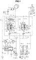
- the hydraulic circuit system of this embodiment comprises a variable displacement hydraulic pump 1, a horsepower control valve (referred to as a PQ valve hereinafter) 12 for controlling a tilting of the hydraulic pump 1 depending on consumed horsepower, and an LS-control bleed valve 2 for bleeding a hydraulic fluid delivered from the hydraulic pump 1 to a reservoir T depending on a difference between a delivery pressure of the hydraulic pump 1 and a signal pressure Pc (described later) based on a maximum load pressure.
- a horsepower control valve referred to as a PQ valve hereinafter
- Pc signal pressure
- the hydraulic fluid delivered from the hydraulic pump 1 is supplied to a plurality of hydraulic actuators 3-1, 3-2.
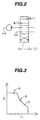
- control valves 4-1, 4-2 including spool-type main valves 4a-1, 4a-2 each of which has a meter-in variable throttle M/I and a meter-out variable throttle M/O as shown in Fig. 2.
- the hydraulic actuator 3-1 is a hydraulic motor (swing motor) for turning an upper swing body of a hydraulic excavator
- the hydraulic actuator 3-2 is a hydraulic cylinder (boom cylinder) for moving a boom of the hydraulic excavator up and down. While only two actuators are shown in this embodiment, it is a matter of course that the number of actuators usable is not limited to two.
- Fig. 1 shows the meter-in variable throttle M/I and the meter-out variable throttle M/O, which are only associated with one shift position of each of the main valves 4a-1, 4a-2, in a manner separated into the meter-in side and the meter-out side.
- the throttles M/I and M/O of the main valve 4a-1 correspond to the shift position for turning the swing body to the right or left
- the throttles M/I and M/O of the main valve 4a-2 correspond to the shift position for raising the boom (i.e., for operating the boom cylinder 3-2 in the direction of extension thereof).
- control valves 4-1, 4-2 incorporate therein flow distribution valves 5-1, 5-2 for achieving the combined operation and hold check valves 6-1, 6-2, respectively.
- the flow distribution valve 5-1 and the hold check valve 6-1 are disposed between the meter-in variable throttle M/I and the hydraulic actuator 3-1.
- the flow distribution valve 5-1 is disposed between the meter-in variable throttle M/I and the hold check valve 6-1.
- the flow distribution valve 5-1 has a valve body 50 that is moved through its stroke within a housing to change an opening area between an inlet passage 5a and an outlet passage 5b.
- a control chamber 70 is formed behind the valve body 50.
- the valve body 50 has a valve-opening-direction acting end (pressure bearing sector) positioned in the inlet passage 5a and a valve-closing-direction acting end (pressure bearing sector) positioned in the control chamber 70.
- the valve body 50 is moved through its stroke depending on balance between a pressure in the control chamber 70 and a pressure in the inlet passage 5a to make control such that the pressure in the inlet passage 5a is kept equal to the pressure in the control chamber 70.
- a differential pressure across the meter-in variable throttle M/I of the main valve 4a-1 is thereby controlled.
- a hydraulic line slit 20 is formed in an outer periphery of the valve body 50 and is opened to the outlet passage 5b.
- An end portion 20a of the hydraulic line slit 20 on the side nearer to the control chamber 70 is not opened to an end of the valve body 50 so that, when the valve body 50 is in the closed position as shown, a lap portion 32 having a lap amount X is formed between the hydraulic line slit 20 and the control chamber 70 to cut off communication therebetween.
- the hydraulic line slit 20 is opened to the control chamber 70.
- the lap portion 32 functions as a dead zone in the operation of the valve body 50.
- the control chamber 70 is connected to a signal transmitting hydraulic line 9 through a hydraulic line 31-1, and a 2-position, 3-way valve 11, which is a feature of the present invention, is disposed in the hydraulic line 31-1.
- the hydraulic line slit 20 and the lap portion 32 constitute a first hydraulic line with a check valve function, which is branched from a point between the meter-in variable throttle M/I and the hydraulic actuator 3-1 and detects a pressure at the branched point, and which is connected to the control chamber 70 of the flow distribution valve 5-1.
- the hydraulic line 31-1 constitutes a second hydraulic line for connecting the control chamber 70 to the signal transmitting hydraulic line.
- the first hydraulic line with the check valve function (i.e., the hydraulic line slit 20 and the lap portion 32) is branched from a point between the meter-in variable throttle M/I and the hold check valve 6-1, more precisely, between the flow distribution valve 5-1 and the hold check valve 6-1, and detects a pressure at the branched point.
- the lap portion 32 effects a check valve function for allowing the load pressure to be detected only when the load pressure of the associated hydraulic actuator 3-1 is a maximum one (as described later).
- a larger diameter portion 50a is formed at an end of the valve body 50 of the flow distribution valve 5-1 on the side of the inlet passage 5a so that a pressure bearing area Ai of the valve body 50 on the side of the inlet passage 5a and a pressure bearing area Ac thereof on the side of the control chamber 70 satisfies a relationship of Ai > Ac.
- This arrangement reduces the influence of a flow force acting upon the valve body 50.
- the control valve 4-2 on the side of the hydraulic actuator 3-2 includes the flow distribution valve 5-2 that is constructed similarly to the above-described flow distribution valve 5-1 of the control valve 4-1.
- identical components of the control valve 4-2 to those of the control valve 4-1 are denoted by the same main numerals added with the sub-numeral 2 in place of 1 and a description thereof is omitted here.
- a 2-position, 3-way valve is not disposed in a hydraulic line 31-2.
- a lower-pressure detecting hydraulic line 35 is connected, as a third hydraulic line, to an outlet passage 5b of the flow distribution valve 5-2 of the control valve 4-2, and a check valve 36 is disposed in the lower-pressure detecting hydraulic line 35.
- the check valve 36 blocks off a flow of the hydraulic fluid from the side of the flow distribution valve 5-2 when the load pressure of the hydraulic actuator 3-2 is higher than the load pressure of the hydraulic actuator 3-1.
- the 2-position, 3-way valve 11 disposed in the control valve 4-1 on the side of the hydraulic actuator 3-1 has one inlet port 11a and two outlet ports 11b, 11c.
- the inlet port 11a is connected to a portion of the hydraulic line 31-1 on the side nearer to the control chamber 70.
- One outlet port 11b is connected to the signal detecting hydraulic 9, and the other outlet port 11c is connected to the outlet passage 5b of the flow distribution valve of the control valve 4-2 on the side of the hydraulic actuator 3-2 via the lower-pressure detecting hydraulic line 35.
- the 2-position, 3-way valve 11 has a hydraulically operating sector lid to which a hydraulic signal is introduced as an external signal F.
- the 2-position, 3-way valve 11 is in a position I, and when the external signal F is applied to the hydraulically operating sector 11d, the 2-position, 3-way valve 11 is shifted to a position II.
- the 2-position, 3-way valve 11 is in the position I, the inlet port 11a is connected to the outlet port 11b only, causing the control chamber 70 of the flow distribution valve 5-1 to be connected to only the signal transmitting hydraulic line 9.
- the 2-position, 3-way valve 11 is in the position II, the inlet port 11a is connected to both the outlet ports 11b and 11c, causing the control chamber 70 to be connected to both the signal transmitting hydraulic line 9 and the lower-pressure detecting hydraulic line 35.
- the main valves 4a-1, 4a-2 of the control valves 4-1, 4-2 are operated respectively by remote control valves 41-1, 41-2, and the external signal F is produced using output pressures of the remote control valves 41-1, 41-2. More specifically, the remote control valves 41-1, 41-2 produce pilot pressures depending on amounts, by which those valves are operated, by utilizing a pressure of a pilot hydraulic fluid source 40 as a source pressure.
- the pilot pressure produced by the remote control valve 41-1 is introduced to the throttles M/I and M/O of the main valve 4a-1 via a pilot hydraulic line 43-1, and the pilot pressure produced by the remote control valve 41-2 is introduced to the throttles M/I and M/O of the main valve 4a-2 via a pilot hydraulic line 43-2.
- the pilot pressure in the pilot hydraulic line 43-1 is used in turning the upper swing body to the right or left, and the pilot pressure in the pilot hydraulic line 43-2 is used in raising the boom.
- An AND circuit 42 comprising a valve group of selector valves 42-1, 42-2 are disposed in a branch hydraulic line 44 branched from the hydraulic fluid source 40. Operating sectors of the selector valves 42-1, 42-2 are connected respectively to the pilot hydraulic lines 43-1, 43-2. When both the remote control valves 41-1, 41-2 are operated and the pilot pressures are produced in both the pilot hydraulic lines 43-1, 43-2, the selector valves 42-1, 42-2 are both shifted from the positions shown, whereby the pressure of the pilot hydraulic fluid source 40 is outputted as the external signal F.
- the PQ valve 12 functions to control a tilting of the hydraulic pump 1 so that the product (horsepower) of a delivery pressure P1 of the hydraulic pump 1 and a delivery rate Q of the hydraulic pump 1 is held constant.
- the delivery rate Q of the hydraulic pump 1 is controlled so as to reduce with an increase in the delivery pressure P1 of the hydraulic pump 1.
- the bleed valve 2 comprises a valve body 2a, a spring chamber 2b in which a valve-closing-direction acting end of the valve body 2a is positioned, and a spring 2c disposed in the spring chamber 2b for biasing the valve body 2a in the valve closing direction.
- the spring chamber 2b is connected to the signal transmitting hydraulic line 9 through a throttle 15 for introducing the signal pressure detected in the signal transmitting hydraulic line 9 to the spring chamber 2b.
- the bleed valve 2 functions such that, when a difference between P1 and Pc exceeds a differential pressure ⁇ PL set by the spring 2c, an extra flow from the hydraulic pump 1 is returned to the reservoir T.
- a differential pressure created depending on the flow rate of the hydraulic fluid passing each of the control valves 4-1, 4-2, i.e., a differential pressure between the inlet pressure ( P1) of the meter-in variable throttle M/I and the signal pressure Pc in the signal transmitting hydraulic line 9, exceeds ⁇ PL.
- Numeral 21 denotes a main relief valve for protecting the main circuit
- 22 denotes an auxiliary relief valve for protecting the signal circuit.
- Fig. 4 shows an equivalent circuit for explaining the load-pressure detecting function of the control valves 4-1, 4-2.
- a load-pressure detecting hydraulic line 7-1 is branched from a hydraulic line 30-1 between the outlet passage 5b of the flow distribution valve 5-1 and the hold check valve 6-1 in the control valve 4-1, and is connected to the signal transmitting hydraulic line 9.
- a control hydraulic line 10-1 is branched from the load-pressure detecting hydraulic line 7-1 and connected to the control chamber 70.
- a check valve 8-1 allowing the hydraulic fluid to flow only in a direction toward the signal transmitting hydraulic line 9 from the hydraulic line 30-1 is provided in a hydraulic line portion 7a of the load-pressure detecting hydraulic line 7-1 between a branched point from the hydraulic line 30-1 and a branched point to the control hydraulic line 10-1.
- the 2-position, 3-way valve 11 is disposed in a hydraulic line portion 7b of the load-pressure detecting hydraulic line 7-1 between the branched point to the control hydraulic line 10-1 and the signal transmitting hydraulic line 9.
- the hydraulic line slit 20 corresponds to the hydraulic line portion 7a of the load-pressure detecting hydraulic line 7-1
- the hydraulic line 31-1 corresponds to the hydraulic line portion 7b of the load-pressure detecting hydraulic line 7-1
- the lap portion 32 corresponds to the check valve 8-1 and the control hydraulic line 10-1.
- the load-pressure detecting function on the side of the control valve 4-2 is essentially the same as that of the control valve 4-2 except for that a 2-position, 3-way valve is not provided.
- the load-pressure detecting hydraulic lines each provided with the check valve function are incorporated as respective internal passages of the flow distribution valves 5-1, 5-2.
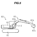
- Fig. 5 shows an appearance of a hydraulic excavator in which the hydraulic circuit system of this embodiment is equipped.
- numeral 80 denotes a hydraulic excavator.
- the hydraulic excavator 80 comprises a lower track structure 81, an upper swing body 82 turning on the lower track structure 81, and a front device 83 provided on the upper swing body 82.
- the front device 83 comprises a boom 83a mounted to the upper swing body 82 to be able to move in the vertical direction, an arm 83b coupled to a fore end of the boom 83a to be able to move in the vertical and back-to-forth directions, and a bucket 83c coupled to a fore end of the arm 83b to be able to move in the vertical and back-to-forth directions.
- the upper swing body 82 is driven for swing by the hydraulic actuator (swing motor) 3-1 shown in Fig. 1, and the boom 83a is driven for rotating in the vertical direction by the hydraulic actuator (boom cylinder) 3-2.
- the 2-position, 3-way valve 11 is in the position I.
- the meter-in variable throttle M/I of the main valve 4-1 is opened and the hydraulic fluid delivered from the hydraulic pump 1 is supplied to the hydraulic actuator 3-1 via the meter-in variable throttle M/I and the flow distribution valve 5-1.
- the valve body 50 of the flow distribution valve 5-1 is opened by being moved upward as viewed in the drawing, causing the hydraulic line slit 20 to be opened to the control chamber 70.
- the load pressure of the hydraulic actuator 3-1 is detected by the hydraulic line slit 20, the control chamber 70 and the hydraulic line 30-1 (the load-pressure detecting hydraulic line 7-1 in Fig. 4).
- the detected load pressure is introduced, as the signal pressure Pc, to the signal transmitting hydraulic line 9.
- the signal pressure Pc is then introduced to the spring chamber 2b of the bleed valve 2, which controls the delivery pressure P1 of the hydraulic pump 1 so as to be kept higher than the signal pressure Pc by the setting value ⁇ PL of the spring 2c.
- the pressure in the inlet passage 5a (also referred to as the inlet pressure hereinafter) of the flow distribution valve 5-1 is P2
- the pressure in the outlet passage 5b (also referred to as the outlet pressure hereinafter) thereof is P3
- the pressure in the control chamber 70 (also referred to as the control pressure hereinafter) is P4
- a pressure loss caused in the hold check valve 6-1 is very small and the outlet pressure P3 of the flow distribution valve 5-1 is almost equal to the load pressure of the hydraulic actuator 3-1.
- the AND circuit 42 comprising the selector valves 42-1, 42-2 outputs the external signal F, and the 2-position, 3-way valve 11 is shifted to the position II by the external signal F.
- the control chamber 70 is connected, as described above, to both the signal transmitting hydraulic line 9 and the lower-pressure detecting hydraulic line 35, that is to say, to the output passage of the flow distribution valve 5-2 on the side of the hydraulic actuator 3-2 as well.
- the hydraulic actuator 3-1 is the hydraulic motor (swing motor) for turning the upper swing body 82 of the hydraulic excavator
- the hydraulic actuator 3-2 is the hydraulic cylinder (boom cylinder) for moving the boom 83a of the hydraulic excavator in the vertical direction.
- the pilot pressure outputted to the pilot hydraulic line 43-1 from the remote control valve 41-1 is used to turn the upper swing body to the right or left
- the pilot pressure outputted to the pilot hydraulic line 43-2 from the remote control valve 41-2 is used to raise the boom. Accordingly, the above-mentioned combined operation is implemented as an operation of turning the upper swing body and raising the boom simultaneously.
- the load pressure of the hydraulic actuator 3-1 (swing motor) is higher than the load pressure of the hydraulic actuator 3-2 (boom cylinder), thus resulting in that the hydraulic actuator 3-1 is on the higher load pressure side and the hydraulic actuator 3-2 is on the lower load pressure side.
- the outlet pressure P3 of the flow distribution valve 5-1 is almost equal to the inlet pressure P2 thereof and is detected as the signal pressure Pc in the signal transmitting hydraulic line 9.
- a value close to the inlet pressure P2 is detected as the signal pressure Pc under the condition that the flow rate is small and the signal transmitting hydraulic line 9 is closed by a throttle 14.
- the flow distribution valve 5-2 develops a throttling operation because of the pump delivery pressure P1 being increased to a high level, and hence produces an extra pressure loss therein.
- the PQ valve 12 having the characteristic shown in Fig. 3 controls the hydraulic pump 1 to shift from an operating point (A) to an operating point (B) in Fig. 3, whereby the delivery rate Q of the hydraulic pump 1 is reduced.
- the 2-position, 3-way valve 11 is provided in the hydraulic line 31-1 (the hydraulic line portion 7b of the load-pressure detecting hydraulic line 7-1 in Fig. 4), and the 2-position, 3-way valve 11 is shifted to the position II during the combined operation of swing and boom-raising so that the control chamber 70 is connected to both the signal transmitting hydraulic line 9 and the lower-pressure detecting hydraulic line 35. Therefore, the signal transmitting hydraulic line 9 is also opened to the outlet passage 5b of the flow distribution valve 5-2 on the side of the hydraulic actuator 3-2 via the lower-pressure detecting hydraulic line 35 and the check valve 36, whereby the load pressure of the hydraulic actuator 3-2 on the lower load pressure side is detected, as the signal pressure Pc, by the signal transmitting hydraulic line 9.
- the bleed valve 2 When the load pressure on the side of the hydraulic actuator 3-2 is detected, the bleed valve 2 is operated so as to compensate the detected pressure, and the delivery pressure P1 of the hydraulic pump 1 is controlled to be kept higher than the load pressure of the hydraulic actuator 3-2 by the setting value ⁇ PL. Accordingly, the flow distribution valve 5-2 does not develop a throttling operation, and can prevent an extra pressure loss from being produced therein. Further, since a reduction in the pump delivery rate due to the action of the PQ valve 12 is suppressed, the hydraulic fluid can be supplied to the hydraulic actuator 3-2 at a required flow rate and the boom 83a can be raised in sufficient amount.
- driving the upper swing body 82 which is a load of the swing motor 3-1
- the upper swing body 82 can be moved by a force greater than a frictional force produced by the upper swing body 82.
- the swing motor 3-1 can be moved with the driving pressure on the side of the boom cylinder 3-1.
- the load pressure of the hydraulic actuator 3-1 is reduced, and therefore the driving pressure of the hydraulic actuator 3-1 may be reduced midway before the hydraulic actuator 3-2 reaches its stroke end.
- the check valve 36 is not provided in the lower-pressure detecting hydraulic line 35, there would occur a risk that the load pressure of the hydraulic actuator 3-1 is detected as the signal pressure Pc by the signal transmitting hydraulic line 9 and the hydraulic actuator 3-2 cannot be driven any more.
- the check valve 36 is provided in the lower-pressure detecting hydraulic line 35, the load pressure of the hydraulic actuator 3-1 is never detected as the signal pressure Pc by the signal transmitting hydraulic line 9 and the hydraulic actuator 3-2 can be positively driven.
- the load pressure of the hydraulic actuator 3-2 on the lower load pressure side is detected as the signal pressure, and the delivery pressure of the hydraulic pump 1 is controlled by the bleed valve 2 for driving the swing motor 3-1 and the boom cylinder 3-2. It is therefore possible to prevent an extra pressure loss from being produced in the flow distribution valve 5-2 on the side of the boom cylinder 3-2, and to reduce an energy loss. Further, the boom 83a can be raised sufficiently and the operability is improved when the upper swing body is turned and the boom is raised at the same time.
- the boom cylinder 3-2 can be positively driven.
- the load-pressure detecting hydraulic line of each control valve 4-1, 4-2 is formed as the internal passage (the hydraulic line slit 20) of the flow distribution valve 5-1, 5-2, and the internal passage is utilized to provide the check valve function. Therefore, a dedicated hydraulic line and valve element in the form of a check valve are no longer required, and the load-pressure detecting function can be realized with a simplified structure.
- the swing load pressure can be cut off by providing an on/off valve in the hydraulic line 31-1 of the control valve 4-1 (the hydraulic line portion 7b of the load-pressure detecting hydraulic line 7-1 in Fig. 4) and closing the on/off valve during the combined operation.
- the signal pressure (the load pressure of the boom cylinder 3-2) in the signal transmitting hydraulic line 9 cannot be introduced to the control chamber 70 and the flow distributing function fails to develop.
- the 2-position, 3-way valve 11 is provided in the hydraulic line 31-1 to provide the function of detecting the lower load pressure. As a result, the function of introducing the signal pressure in the signal transmitting hydraulic line 9 to the control chamber 70 is maintained and the flow distributing function is not impaired.
- the hydraulic line with the check valve function (the hydraulic line portion 7a of each load-pressure detecting hydraulic line 7-1, 7-2 including the check valve 8-1, 8-2), which is constituted by the hydraulic line slit 20 and the lap portion 32, is branched from the hydraulic line 30-1, 30-2 between the flow distribution valve 5-1, 5-2 and the hold check valve 6-1, 6-2 and detects a pressure in the hydraulic line 30-1, 30-2 as the load pressure.
- each hydraulic actuator 3-1, 3-2 is increased beyond the pressure at the meter-in variable throttle M/I of the main valve 4a-1, 4a-2, the load pressure is held by the hold check valve 6-1, 6-2 and the hydraulic fluid is avoided from reversely flowing into the reservoir T via the load-pressure detecting hydraulic line 7-1, 7-2, the signal detecting hydraulic line 9 and the throttle 14.
- a second embodiment of the present invention will be described with reference to Fig. 6.
- the present invention is intended to improve the operation when the boom cylinder reaches its stroke end.
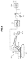
- an angle sensor 85 for detecting an angle of rotation of the boom 83a is provided at a base end serving as a fulcrum about which the boom 83a rotates, and a detection signal from the angle sensor 85 is inputted to a controller 86. Based on the detection signal from the angle sensor 85, the controller 86 determines whether the hydraulic actuator 3-2 has reached the stroke end. If it is determined that the hydraulic actuator 3-2 has reached the stroke end, the controller 86 outputs an electrical signal to a solenoid selector valve 87. When the electrical signal is applied, the solenoid selector valve 87 is shifted to an open position, whereupon the pilot pressure of the pilot hydraulic source 40 is outputted as an external signal Z to a pilot check valve 36A.
- the pilot check valve 36A is provided, for example, in place of the check valve 36 shown in Fig. 1, and is operated so as to open upon the external signal Z (pilot pressure) being applied from the solenoid selector valve 87.
- this embodiment when the angle sensor 86 and the controller 86 detect a condition that the hydraulic actuator 3-2 is in the vicinity of the stroke end, the solenoid selector valve 87 applies the pilot pressure, as the external signal Z, to the pilot check valve 36A to open it, whereby the pressure in the signal transmitting hydraulic line 9 is given by the pressure on the side of the hydraulic actuator 3-1.
- this embodiment contributes to providing a more appropriate working speed and reducing an energy loss.
- the stroke end of the hydraulic actuator 3-2 may also be detected by, rather than the angle sensor, a stroke sensor or a pressure sensor for detecting the load pressure of the hydraulic actuator 3-2.
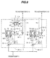
- FIG. 7 and 8 A third embodiment of the present invention will be described with reference to Figs. 7 and 8.
- the load pressure is detected at a different position.
- identical members to those in Figs. 1 and 4 are denoted by the same numerals.
- a control valve 4B-1 in the third embodiment of the present invention includes a flow distribution valve 5B-1.
- a valve body 50B of the flow distribution valve 5B-1 has an internal passage 20B which is formed therein and opened at one end to an inlet passage 5a.
- An opposite end portion 20a of the internal passage 20B is opened to an outer peripheral surface of the valve body 50B so that, when the valve body 50B is in the closed position as shown, a lap portion 32 having a lap amount X is formed between the open end portion 20a of the internal passage 20B and the control chamber 70 to cut off communication therebetween.
- the valve body 50B is moved through its stroke from the shown closed position in excess of the lap amount X, the internal passage 20B is opened to the control chamber 70.
- the internal passage 20B and the lap portion 32 constitute a first hydraulic line with a check valve function, which is branched from a point between the meter-in variable throttle M/I and the hydraulic actuator 3-1 and detects a pressure at the branched point, and which is connected to the control chamber 70 of the flow distribution valve 5B-1.
- the first hydraulic line with the check valve function i.e., the hydraulic line slit 20 and the lap portion 32
- the 2-position, 3-way valve 11 which is a feature of the present invention, is disposed in the hydraulic line 31-1.
- a flow distribution valve 5B-2 on the side of the control valve 4B-2 shown in Fig. 7 is constructed similarly to the above-described flow distribution valve 5B-1. However, a 2-position, 3-way valve is not disposed in a hydraulic line 31-2.
- a lower-pressure detecting hydraulic line 35 is connected, as a third hydraulic line, to an outlet passage 5b of the flow distribution valve 5B-2 and a check valve 36 is disposed in the lower-pressure detecting hydraulic line 35.
- Fig. 8 is an equivalent circuit, similar to that of Fig. 4, for explaining the load-pressure detecting function of the control valves 4B-1, 4B-2.
- a load-pressure detecting hydraulic line 7B-1 is branched from a hydraulic line 29-1 between the meter-in variable throttle M/I of the main valve 4a-1 in the control valve 4B-1 and the inlet passage 5a of the flow distribution valve 5B-1, and is connected to the signal transmitting hydraulic line 9.
- a control hydraulic line 10-1 is branched from the load-pressure detecting hydraulic line 7B-1 and connected to the control chamber 70.
- a check valve 8-1 allowing the hydraulic fluid to flow only in a direction toward the signal transmitting hydraulic line 9 from the hydraulic line 20-1 is provided in a hydraulic line portion 7a of the load-pressure detecting hydraulic line 7B-1 on the inlet side thereof.
- the 2-position, 3-way valve 11 is disposed in a hydraulic line portion 7b of the load-pressure detecting hydraulic line 7B-1 between a branched point to the control hydraulic line 10-1 and the signal transmitting hydraulic line 9.
- the internal passage 20B corresponds to the hydraulic line portion 7a of the load-pressure detecting hydraulic line 7B-1
- the hydraulic line 31-1 corresponds to the hydraulic line portion 7b of the load-pressure detecting hydraulic line 7B-1
- the lap portion 32 corresponds to the check valve 8-1 and the control hydraulic line 10-1.
- the load-pressure detecting function on the side of the control valve 4-2B is essentially the same as that of the control valve 4B-2 except for that a 2-position, 3-way valve is not provided.
- the load-pressure detecting hydraulic lines each provided with the check valve function are incorporated as respective internal passages of the flow distribution valves 5B-1, 5B-2.
- this embodiment can also provide similar advantages to those in the first embodiment.
- the bleed 2 is employed as the pump control means for the load sensing system.
- a tilting controller 2A may be used to perform tilting control of a hydraulic pump 1A so that the delivery pressure P1 of the hydraulic pump 1 is kept higher than the signal pressure Pc of the signal transmitting hydraulic line 9 by the setting value ⁇ PL of the spring 2d. Similar advantages to those described above can also be obtained in the case where the present invention is applied to a hydraulic circuit system having such a load sensing system.
- a pressure on the lower load pressure side is detected as a signal pressure.
- swing and boom-raising for example, which is performed in the work of loading excavated earth and sand on a dump truck, it is therefore possible to prevent an extra pressure loss from being produced in a flow distribution valve portion of a second particular control valve, and to reduce an energy loss.
- a hydraulic fluid can be supplied to the side of the second particular control valve at a sufficient flow rate and good operability can be obtained in the combined operation.
- a load-pressure detecting hydraulic line of each control valve is formed as an internal passage (hydraulic line slit) of a flow distribution valve and the internal passage (hydraulic line slit) is utilized to provide a check valve function, a load-pressure detecting function of the control valve can be realized with a simplified structure.
- the same function as resulted from not detecting a pressure on the side of a first particular control valve is provided by, rather than cutting off a hydraulic line, connecting a control chamber to both a signal transmitting hydraulic line and a lower-pressure detecting hydraulic line (outlet side of the flow distribution valve in the second particular control valve). Therefore, a function of introducing a pressure on the side of the second particular control valve to the control chamber is maintained and the flow distributing function is not impaired.
- a first hydraulic line is branched from a hydraulic line between the flow distribution valve and a hold check valve and detects a pressure in the hydraulic line therebetween as a load pressure. Therefore, even when the load pressure of a hydraulic actuator is increased beyond the pressure at a meter-in variable throttle M/I of a main valve, the load pressure is held by the hold check valve and the hydraulic fluid is avoided from reversely flowing into a reservoir via the first hydraulic line, a second hydraulic line, a signal detecting hydraulic line and a first throttle.
- a pilot check is opened so that the signal pressure in the signal transmitting hydraulic line is given by the pressure on the side of the first particular control valve.
Landscapes
- Engineering & Computer Science (AREA)
- General Engineering & Computer Science (AREA)
- Physics & Mathematics (AREA)
- Fluid Mechanics (AREA)
- Mechanical Engineering (AREA)
- Mining & Mineral Resources (AREA)
- Civil Engineering (AREA)
- Structural Engineering (AREA)
- Fluid-Pressure Circuits (AREA)
- Operation Control Of Excavators (AREA)
- Control Of Transmission Device (AREA)
Abstract
Description
Claims (8)
- A hydraulic circuit system comprising a hydraulic pump (1), a plurality of hydraulic actuators (3-1, 3-2) driven by a hydraulic fluid delivered from said hydraulic pump, a plurality of control valves (4-1, 4-2) disposed between said hydraulic pump and said plurality of actuators, a signal transmitting hydraulic line (9) to which a signal pressure based on a maximum load pressure among said plurality of hydraulic actuators is introduced, and pump control means (2) for controlling a delivery pressure of said hydraulic pump to be held higher than said signal pressure by a predetermined value,said plurality of control valves comprising respectively main valves (4a-1, 4a-2) including meter-in variable throttles (M/I) for controlling flow rates of the hydraulic fluid supplied to said hydraulic actuators, andflow distribution valves (5-1, 5-2) disposed between said meter-in variable throttles and said actuators, each of said flow distribution valves including a valve body (50) which has one end positioned on the inlet side (5a) of said flow distribution valve connected to said meter-in variable throttle and the other end positioned in a control chamber (70), said valve body being moved through a stroke depending on balance between a pressure in said control chamber and a pressure in said inlet side to control the pressure in said inlet side, thereby controlling a differential pressure across said meter-in variable throttle, wherein:said hydraulic circuit system further comprises a load-pressure detecting hydraulic line (20, 32, 31-1, 31-2; 7a, 8-1, 8-2, 10-1, 10-2, 7b) provided in each of said plurality of control valves (4-1, 4-2), said load-pressure detecting hydraulic line including a first hydraulic line (20, 32; 7a, 8-1, 8-2, 10-1, 10-2) with a check valve function, which is branched from a point between said meter-in variable throttle (M/I) and said hydraulic actuator (3-1, 3-2) for detecting a pressure at the branched point, and is connected to said control chamber (70) of said flow distribution valve (5-1, 5-2), and a second hydraulic line (31-1, 31-2, 7b) for connecting said control chamber to said signal transmitting hydraulic line (9), said first hydraulic line with the check valve function including a valve body passage (20), which is formed in a valve body (50) of said flow distribution valve (5-1, 5-2) and has one end being opened to one of the inlet side (5a) and the outlet side (5b) of said flow distribution valve and the other end being opened to an outer periphery of said valve body, and a lap portion (32) located between the other end (20a) of said valve body passage and said control chamber (70) and making the other end of said valve body passage opened to said control chamber when the valve body of said flow distribution valve is moved through a stroke of a predetermined distance in the valve opening direction;a selector valve (11) provided in said second hydraulic line (31-1) of said load-pressure detecting hydraulic line in a first particular control valve (4-1) of said plurality of control valves; anda third hydraulic line (35) connected to the outlet side (5b) of said flow distribution valve in a second particular control valve (4-2) of said plurality of control valves,said selector valve (11) having a first position (I) at which only a portion of said second hydraulic line (31-1) on the side of said control chamber is connected to said signal transmitting hydraulic line (9), and a second position (II) at which the portion of said second hydraulic line (31-1) on the side of said control chamber is connected to both said signal transmitting hydraulic line (9) and said third hydraulic line (35).
- A hydraulic circuit system according to Claim 1, wherein said plurality of control valves (4-1, 4-2) further comprise respectively hold check valves (6-1, 6-2) disposed between said flow distribution valves (5-1, 5-2) and said hydraulic actuators (3-1, 3-2), and said first hydraulic line (20, 32; 7a, 8-1, 8-2, 10-1, 10-2) with the check valve function is branched from a point between said meter-in variable throttle (M/I) and each of said hold check valves (6-1, 6-2) to detect a pressure at the branched point.
- A hydraulic circuit system according to Claim 1 or 2, wherein said plurality of control valves (4-1, 4-2) each include a hydraulic line slit (20) formed in the outer periphery of the valve body (50) of said flow distribution valve and opened at one end to the outlet side (5b) of said flow distribution valve, said hydraulic line slit constituting said valve body passage.
- A hydraulic circuit system according to Claim 1, further comprising means (42) for producing a first signal (F) when said first and second particular control valves (4-1, 4-2) are both operated,
wherein said selector valve (11) is shifted from said first position to said second position by said first signal. - A hydraulic circuit system according to Claim 1, further comprising a check valve (36) disposed in said third hydraulic line (35) and allowing the hydraulic fluid to flow only in a direction toward said flow distribution valve (5-2) of said second particular control valve (4-2) from said selector valve (11).
- A hydraulic circuit system according to Claim 5, wherein said check valve is a pilot check (36A) capable of being selectively opened.
- A hydraulic circuit system according to Claim 6, further comprising means (85, 86, 87) for producing a second signal (Z) when said hydraulic actuator (3-2) associated with said second particular control valve (4-2) reaches a stroke end,
wherein said pilot check (36A) is opened by said second signal. - A hydraulic circuit system comprising a hydraulic pump (1), a plurality of hydraulic actuators (3-1, 3-2) driven by a hydraulic fluid delivered from said hydraulic pump, a plurality of control valves (4-1, 4-2) disposed between said hydraulic pump and said plurality of actuators, a signal transmitting hydraulic line (9) to which a signal pressure based on a maximum load pressure among said plurality of hydraulic actuators is introduced, and pump control means (2) for controlling a delivery pressure of said hydraulic pump to be held higher than said signal pressure by a predetermined value,said plurality of control valves comprising respectively main valves (4a-1, 4a-2) including meter-in variable throttles (M/I) for controlling flow rates of the hydraulic fluid supplied to said hydraulic actuators, andflow distribution valves (5-1, 5-2) disposed between said meter-in variable throttles and said actuators, each of said flow distribution valves including a valve body (50) which has one end positioned on the inlet side (5a) of said flow distribution valve connected to said meter-in variable throttle and the other end positioned in a control chamber (70), said valve body being moved through a stroke depending on balance between a pressure in said control chamber and a pressure in said inlet side to control the pressure in said inlet side, thereby controlling a differential pressure across said meter-in variable throttle, wherein:said hydraulic circuit system further comprises a load-pressure detecting hydraulic line (7a, 8-1, 8-2, 10-1, 10-2, 7b) provided in each of said plurality of control valves (4-1, 4-2), said load-pressure detecting hydraulic line including a first hydraulic line (7a, 8-1, 8-2, 10-1, 10-2) with a check valve function, which is branched from a point between said meter-in variable throttle (M/I) and said hydraulic actuator (3-1, 3-2) for detecting a pressure at the branched point, and is connected to said control chamber (70) of said flow distribution valve (5-1, 5-2), and a second hydraulic line (7b) for connecting said control chamber to said signal transmitting hydraulic line (9);a selector valve (11) provided in said second hydraulic line (31-1) of said load-pressure detecting hydraulic line in a first particular control valve (4-1) of said plurality of control valves; anda third hydraulic line (35) connected to the outlet side (5b) of said flow distribution valve in a second particular control valve (4-2) of said plurality of control valves,said selector valve (11) having a first position (I) at which only a portion of said second hydraulic line (31-1) on the side of said control chamber is connected to said signal transmitting hydraulic line (9), and a second position (II) at which the portion of said second hydraulic line (31-1) on the side of said control chamber is connected to both said signal transmitting hydraulic line (9) and said third hydraulic line (35).
Applications Claiming Priority (3)
| Application Number | Priority Date | Filing Date | Title |
|---|---|---|---|
| JP11864499 | 1999-04-26 | ||
| JP11864499 | 1999-04-26 | ||
| PCT/JP2000/002170 WO2000065238A1 (en) | 1999-04-26 | 2000-04-04 | Hydraulic circuit device |
Publications (2)
| Publication Number | Publication Date |
|---|---|
| EP1088995A1 true EP1088995A1 (en) | 2001-04-04 |
| EP1088995A4 EP1088995A4 (en) | 2006-04-05 |
Family
ID=14741665
Family Applications (1)
| Application Number | Title | Priority Date | Filing Date |
|---|---|---|---|
| EP00913095A Withdrawn EP1088995A4 (en) | 1999-04-26 | 2000-04-04 | HYDRAULIC CIRCUIT ARRANGEMENT |
Country Status (5)
| Country | Link |
|---|---|
| US (1) | US6378302B1 (en) |
| EP (1) | EP1088995A4 (en) |
| KR (1) | KR100379863B1 (en) |
| CN (1) | CN1316038A (en) |
| WO (1) | WO2000065238A1 (en) |
Cited By (2)
| Publication number | Priority date | Publication date | Assignee | Title |
|---|---|---|---|---|
| WO2005066505A1 (en) * | 2004-01-07 | 2005-07-21 | Bosch Rexroth Ag | Flow valve and flow distributor comprising several flow valves |
| EP1837529A1 (en) * | 2006-03-20 | 2007-09-26 | HAWE Hydraulik GmbH & Co. KG | Hydraulic control device |
Families Citing this family (16)
| Publication number | Priority date | Publication date | Assignee | Title |
|---|---|---|---|---|
| US7431043B2 (en) * | 2005-03-17 | 2008-10-07 | Borgwarner Inc. | Automatic transmission having a pressure regulator with flow force compensation |
| US7856999B2 (en) * | 2005-03-17 | 2010-12-28 | Borgwarner Inc. | Automatic transmission having hydraulic valves with flow force compensation |
| DE102007028864A1 (en) * | 2007-03-27 | 2008-10-02 | Robert Bosch Gmbh | Hydraulic control arrangement |
| SE531754C2 (en) * | 2007-05-11 | 2009-07-28 | Nordhydraulic Ab | Hydraulic load control valve device |
| US8046122B1 (en) | 2008-08-04 | 2011-10-25 | Brunswick Corporation | Control system for a marine vessel hydraulic steering cylinder |
| US8376906B2 (en) * | 2008-12-09 | 2013-02-19 | Borgwarner Inc. | Automatic transmission for a hybrid vehicle |
| EP2449290B1 (en) | 2009-06-29 | 2015-10-21 | Borgwarner Inc. | Hydraulic valve for use in a control module of an automatic transmission |
| DE112010003606T5 (en) | 2009-09-10 | 2012-08-23 | Borgwarner Inc. | HYDRAULIC CIRCUIT FOR AN AUTOMATIC TRANSMISSION WITH AN OPEN-CONTROL SWITCH ACTUATOR VALVE THERMAL POWER COMPENSATION |
| US8483916B2 (en) * | 2011-02-28 | 2013-07-09 | Caterpillar Inc. | Hydraulic control system implementing pump torque limiting |
| JP5739066B2 (en) * | 2011-06-27 | 2015-06-24 | ボルボ コンストラクション イクイップメント アーベー | Hydraulic control valve for construction machinery |
| JP5948260B2 (en) * | 2013-01-24 | 2016-07-06 | Kyb株式会社 | Fluid pressure control device |
| CN105443474B (en) * | 2015-12-29 | 2017-05-17 | 太原理工大学 | Control loop for working device of loader |
| FR3060046B1 (en) * | 2016-12-14 | 2020-10-30 | Soletanche Freyssinet | DRILLING MACHINE EQUIPPED WITH FOUR DRILLING UNITS |
| CN107313998B (en) * | 2017-07-17 | 2019-06-18 | 湖南三一港口设备有限公司 | Hydraulic energy-saving system and front crane |
| CN116290163B (en) * | 2023-02-07 | 2025-01-28 | 爱克斯维智能科技(苏州)有限公司 | Automatic flow distribution control method, system, device and excavator |
| CN116733807A (en) * | 2023-08-08 | 2023-09-12 | 山西斯普瑞机械制造股份有限公司 | Pressure and flow double proportional valve |
Family Cites Families (12)
| Publication number | Priority date | Publication date | Assignee | Title |
|---|---|---|---|---|
| JP2721383B2 (en) * | 1989-02-13 | 1998-03-04 | 日立建機株式会社 | Hydraulic circuit of work machine |
| US5209063A (en) * | 1989-05-24 | 1993-05-11 | Kabushiki Kaisha Komatsu Seisakusho | Hydraulic circuit utilizing a compensator pressure selecting value |
| WO1991002902A1 (en) * | 1989-08-16 | 1991-03-07 | Hitachi Construction Machinery Co., Ltd. | Valve device and hydraulic circuit device |
| DE69120818T2 (en) * | 1990-05-15 | 1996-12-05 | Kabushiki Kaisha Komatsu Seisakusho, Tokio/Tokyo | HYDRAULIC SYSTEM |
| EP0491050B1 (en) * | 1990-07-05 | 1995-04-26 | Hitachi Construction Machinery Co., Ltd. | Hydraulic drive system and valve device |
| DE4235707B4 (en) * | 1992-10-22 | 2007-10-18 | Linde Material Handling Gmbh | Hydrostatic drive system |
| DE4235709A1 (en) * | 1992-10-22 | 1994-04-28 | Linde Ag | Hydrostatic drive system |
| DE4417962A1 (en) * | 1994-05-21 | 1995-11-23 | Rexroth Mannesmann Gmbh | Control arrangement for at least two hydraulic consumers |
| KR970011608B1 (en) * | 1994-09-06 | 1997-07-12 | 대우중공업 주식회사 | Apparatus for controlling tunning torque in a construction equipment |
| JPH1037250A (en) * | 1996-07-26 | 1998-02-10 | Komatsu Ltd | Hydraulic circuit |
| KR100289419B1 (en) | 1997-01-21 | 2001-05-02 | 세구치 류이치 | Directional Control Valve with Split Valve |
| DE19703997A1 (en) * | 1997-02-04 | 1998-08-06 | Mannesmann Rexroth Ag | Hydraulic control circuit for a priority and for a subordinate hydraulic consumer |
-
2000
- 2000-04-04 WO PCT/JP2000/002170 patent/WO2000065238A1/en not_active Ceased
- 2000-04-04 KR KR10-2000-7014118A patent/KR100379863B1/en not_active Expired - Fee Related
- 2000-04-04 EP EP00913095A patent/EP1088995A4/en not_active Withdrawn
- 2000-04-04 CN CN00800378A patent/CN1316038A/en active Pending
- 2000-04-04 US US09/674,366 patent/US6378302B1/en not_active Expired - Fee Related
Cited By (3)
| Publication number | Priority date | Publication date | Assignee | Title |
|---|---|---|---|---|
| WO2005066505A1 (en) * | 2004-01-07 | 2005-07-21 | Bosch Rexroth Ag | Flow valve and flow distributor comprising several flow valves |
| US7380491B2 (en) | 2004-01-07 | 2008-06-03 | Bosch Rexroth Ag | Flow valve and flow distributor comprising several flow valves |
| EP1837529A1 (en) * | 2006-03-20 | 2007-09-26 | HAWE Hydraulik GmbH & Co. KG | Hydraulic control device |
Also Published As
| Publication number | Publication date |
|---|---|
| WO2000065238A1 (en) | 2000-11-02 |
| KR100379863B1 (en) | 2003-04-11 |
| US6378302B1 (en) | 2002-04-30 |
| EP1088995A4 (en) | 2006-04-05 |
| KR20010071462A (en) | 2001-07-28 |
| CN1316038A (en) | 2001-10-03 |
Similar Documents
| Publication | Publication Date | Title |
|---|---|---|
| US6378302B1 (en) | Hydraulic circuit system | |
| EP0795690B1 (en) | Hydraulic driving device | |
| US6430922B2 (en) | Construction machine | |
| EP1995155B1 (en) | Traveling device for crawler type heavy equipment | |
| JPH11303809A (en) | Pump control device for hydraulic drive machine | |
| EP3604685B1 (en) | Hydraulic drive device for construction machine | |
| KR940008821B1 (en) | Valve device and hydraulic driving device | |
| US11078646B2 (en) | Shovel and control valve for shovel | |
| KR20190109549A (en) | Control system of construction machinery and control method of construction machinery | |
| JP7304776B2 (en) | CONTROL VALVE GEAR AND HYDRAULIC DRIVING SYSTEM INCLUDING THE SAME | |
| US11466426B2 (en) | Material moving machines and pilot hydraulic switching systems for use therein | |
| JP2018145984A (en) | Hydraulic transmission for construction machine | |
| JP3965932B2 (en) | Hydraulic control circuit of excavator | |
| JP3403535B2 (en) | Control equipment for construction machinery | |
| JP2005140153A (en) | Hydraulic control equipment for construction machinery | |
| KR102142679B1 (en) | Hydraulic Oil Control System for Working Machine | |
| KR20070095446A (en) | Hydraulic drive | |
| JP2002005109A (en) | Operation control device | |
| JP2003028101A (en) | Hydraulic control device for construction machinery | |
| JP3511504B2 (en) | Hydraulic circuit of construction machinery | |
| JP2707413B2 (en) | Hydraulic construction machinery equipped with a variable displacement hydraulic pump | |
| JP3980501B2 (en) | Hydraulic drive unit for construction machinery | |
| JP2978739B2 (en) | Pilot pressure control circuit for construction machinery | |
| WO2025150508A1 (en) | Hydraulic drive system | |
| JP3016004B2 (en) | Work machine interference prevention control circuit device |
Legal Events
| Date | Code | Title | Description |
|---|---|---|---|
| PUAI | Public reference made under article 153(3) epc to a published international application that has entered the european phase |
Free format text: ORIGINAL CODE: 0009012 |
|
| AK | Designated contracting states |
Kind code of ref document: A1 Designated state(s): AT BE CH CY DE DK ES FI FR GB GR IE IT LI LU MC NL PT SE |
|
| 17P | Request for examination filed |
Effective date: 20010423 |
|
| RBV | Designated contracting states (corrected) |
Designated state(s): DE FR GB IT SE |
|
| A4 | Supplementary search report drawn up and despatched |
Effective date: 20060221 |
|
| RIC1 | Information provided on ipc code assigned before grant |
Ipc: F15B 11/05 20060101ALI20060215BHEP Ipc: F15B 11/16 20060101ALI20060215BHEP Ipc: F15B 11/00 20060101AFI20001107BHEP Ipc: E02F 9/22 20060101ALI20060215BHEP |
|
| STAA | Information on the status of an ep patent application or granted ep patent |
Free format text: STATUS: THE APPLICATION IS DEEMED TO BE WITHDRAWN |
|
| 18D | Application deemed to be withdrawn |
Effective date: 20060511 |