EP1088968B1 - Silencer - Google Patents
Silencer Download PDFInfo
- Publication number
- EP1088968B1 EP1088968B1 EP99922499A EP99922499A EP1088968B1 EP 1088968 B1 EP1088968 B1 EP 1088968B1 EP 99922499 A EP99922499 A EP 99922499A EP 99922499 A EP99922499 A EP 99922499A EP 1088968 B1 EP1088968 B1 EP 1088968B1
- Authority
- EP
- European Patent Office
- Prior art keywords
- convex
- plate
- portions
- concave portions
- plates
- Prior art date
- Legal status (The legal status is an assumption and is not a legal conclusion. Google has not performed a legal analysis and makes no representation as to the accuracy of the status listed.)
- Expired - Lifetime
Links
Images


Classifications
-
- F—MECHANICAL ENGINEERING; LIGHTING; HEATING; WEAPONS; BLASTING
- F01—MACHINES OR ENGINES IN GENERAL; ENGINE PLANTS IN GENERAL; STEAM ENGINES
- F01N—GAS-FLOW SILENCERS OR EXHAUST APPARATUS FOR MACHINES OR ENGINES IN GENERAL; GAS-FLOW SILENCERS OR EXHAUST APPARATUS FOR INTERNAL-COMBUSTION ENGINES
- F01N1/00—Silencing apparatus characterised by method of silencing
- F01N1/02—Silencing apparatus characterised by method of silencing by using resonance
-
- F—MECHANICAL ENGINEERING; LIGHTING; HEATING; WEAPONS; BLASTING
- F01—MACHINES OR ENGINES IN GENERAL; ENGINE PLANTS IN GENERAL; STEAM ENGINES
- F01N—GAS-FLOW SILENCERS OR EXHAUST APPARATUS FOR MACHINES OR ENGINES IN GENERAL; GAS-FLOW SILENCERS OR EXHAUST APPARATUS FOR INTERNAL-COMBUSTION ENGINES
- F01N1/00—Silencing apparatus characterised by method of silencing
- F01N1/08—Silencing apparatus characterised by method of silencing by reducing exhaust energy by throttling or whirling
-
- F—MECHANICAL ENGINEERING; LIGHTING; HEATING; WEAPONS; BLASTING
- F01—MACHINES OR ENGINES IN GENERAL; ENGINE PLANTS IN GENERAL; STEAM ENGINES
- F01N—GAS-FLOW SILENCERS OR EXHAUST APPARATUS FOR MACHINES OR ENGINES IN GENERAL; GAS-FLOW SILENCERS OR EXHAUST APPARATUS FOR INTERNAL-COMBUSTION ENGINES
- F01N1/00—Silencing apparatus characterised by method of silencing
- F01N1/08—Silencing apparatus characterised by method of silencing by reducing exhaust energy by throttling or whirling
- F01N1/084—Silencing apparatus characterised by method of silencing by reducing exhaust energy by throttling or whirling the exhaust gases flowing through the silencer two or more times longitudinally in opposite directions, e.g. using parallel or concentric tubes
-
- F—MECHANICAL ENGINEERING; LIGHTING; HEATING; WEAPONS; BLASTING
- F01—MACHINES OR ENGINES IN GENERAL; ENGINE PLANTS IN GENERAL; STEAM ENGINES
- F01N—GAS-FLOW SILENCERS OR EXHAUST APPARATUS FOR MACHINES OR ENGINES IN GENERAL; GAS-FLOW SILENCERS OR EXHAUST APPARATUS FOR INTERNAL-COMBUSTION ENGINES
- F01N1/00—Silencing apparatus characterised by method of silencing
- F01N1/08—Silencing apparatus characterised by method of silencing by reducing exhaust energy by throttling or whirling
- F01N1/089—Silencing apparatus characterised by method of silencing by reducing exhaust energy by throttling or whirling using two or more expansion chambers in series
-
- F—MECHANICAL ENGINEERING; LIGHTING; HEATING; WEAPONS; BLASTING
- F01—MACHINES OR ENGINES IN GENERAL; ENGINE PLANTS IN GENERAL; STEAM ENGINES
- F01N—GAS-FLOW SILENCERS OR EXHAUST APPARATUS FOR MACHINES OR ENGINES IN GENERAL; GAS-FLOW SILENCERS OR EXHAUST APPARATUS FOR INTERNAL-COMBUSTION ENGINES
- F01N2490/00—Structure, disposition or shape of gas-chambers
- F01N2490/02—Two or more expansion chambers in series connected by means of tubes
- F01N2490/06—Two or more expansion chambers in series connected by means of tubes the gases flowing longitudinally from inlet to outlet in opposite directions
-
- F—MECHANICAL ENGINEERING; LIGHTING; HEATING; WEAPONS; BLASTING
- F01—MACHINES OR ENGINES IN GENERAL; ENGINE PLANTS IN GENERAL; STEAM ENGINES
- F01N—GAS-FLOW SILENCERS OR EXHAUST APPARATUS FOR MACHINES OR ENGINES IN GENERAL; GAS-FLOW SILENCERS OR EXHAUST APPARATUS FOR INTERNAL-COMBUSTION ENGINES
- F01N2490/00—Structure, disposition or shape of gas-chambers
- F01N2490/15—Plurality of resonance or dead chambers
- F01N2490/155—Plurality of resonance or dead chambers being disposed one after the other in flow direction
Definitions
- the present invention relates to a muffler.
- a muffler As a conventional internal combustion engine muffler, a muffler has been generally employed which is, as shown in Fig. 7, constituted by dividing a main body formed of a shell 101 and outer plates 102, 103 into expansion chambers 106, 107 and a resonance chamber 108 by inner plates 104, 105. Furthermore, the muffler is constituted of an inlet pipe 109 for introducing exhaust gas, an outlet pipe 110 for discharging the exhaust gas to the atmosphere, and an inner pipe 111 for connecting the respective chambers to each other.
- connection holes 112 for passing the respective pipes are formed in a flat plate molded by press processing, and linear ribs (beads) 114 are formed in a plane portion 113 excluding the connection holes 112, so as to restrain surface vibration of the outer plates 102, 103 and inner plates 104, 105, and to prevent abnormal noise and breakage caused by the surface vibration.
- Document JP2 040 914 U shows another muffler which has an inner dividing plate having adjacent convex and concave portions.
- an object of the present invention is to provide a muffler in which by enhancing vibration-damping effects of outer and inner plates, and by effectively utilizing a limited plate area to form many irregular reflection elements, the exhaust noise can be reduced as compared with the aforementioned conventional plate.
- a muffler in which an inside is divided into a plurality of chambers by at least an inner plate, a plurality of dot-shaped convex and concave portions are provided in at least one of the inner plate and/or the outer plate, the convex portions and the concave portions are alternately arranged in a pattern on said one surface such that one concave portion is surrounded by plural convex portions and one convex portion is surrounded by concave portions and adjacent convex portions and concave portions are connected by a curved surface.
- the present invention since high frequency components of the exhaust noise having hit the dot-shaped convex and concave portions are diffusely reflected to interfere with each other in all spatial directions, the secondary noise is restrained, and the exhaust noise is reduced as compared with the conventional art. Furthermore, since the convex and concave portions are alternately disposed and connected to each other by the curved surfaces, plate surface rigidity is enhanced, and abnormal noise and breakage by plate vibration can also be prevented.
- the convex and concave portions may be disposed substantially on the entire surface of the plate.
- a burring portion for passing a pipe can also be disposed on the convex or concave portion.
- Pipe vibration is restrained by providing the burring portion without deteriorating the plate surface rigidity.
- the convex and concave portions may be provided on the outer and inner plates disposed opposite to each other or the inner plates disposed opposite to each other.
- Fig. 1 shows an embodiment of a muffler in which the present invention is applied to outer and inner plates.
- a main body formed by a shell 1 and outer plates 2, 3 is divided into three chambers 6, 7, 8 by two inner plates 4, 5. Moreover, an inlet pipe 9, an outlet pipe 10, and an inner pipe 11 are passed through the plates and arranged as shown in Fig. 1.
- the respective members are formed of metal plates.
- the outer plates 2, 3 and inner plates 4, 5 are provided with convex and concave portions as irregular reflection elements according to the present invention, and the irregular reflection elements will be described in detail using the inner plate 4 as an example with reference to Figs. 2A to 2C.
- Fig. 2A is a front view of the inner plate 4, and a connection hole 12 in the inlet pipe 9, connection hole 13 in the outlet pipe 10 and connection hole 14 in the inner pipe 11 are formed through the inner plate.
- Fig. 2A The entire surface excluding the respective connection holes 12 to 14 and an outer peripheral portion of the plate 4 is dotted with hemispherical convex portions 15 and hemispherical concave portions 16 formed by press processing with respect to one surface (front surface) of the inner plate 4. Additionally, in Fig. 2A the convex portion 15 is shown by a white circle, and the concave portion 16 is shown by a black circle.
- one convex portion 15 is surrounded with four concave portions 16, and one concave portion 16 is surrounded with four convex portions 15. Furthermore, the convex portion 15 and concave portion 16, the convex portion 15 and convex portion 15, or the concave portion 16 and concave portion 16, which are disposed adjacent to each other, are connected to each other by a smooth curved surface as shown in Figs. 2B, 2C. Furthermore, around the connection holes 12 to 14, burrings 19 for making the pipe pass through are positioned on the convex portions 15 or the concave portions 16 and formed in a bent shape.
- convex portion 15 and concave portion 16 may be provided on the entire surface of the plate, but in the embodiment of Fig. 2A, a plane portion 20 for pressing a jig onto the outer peripheral portion of the plate 4 during insertion of the plate 4 into the shell 1 in a muffler assembly process is provided on the outer peripheral portion of the plate 4.
- a flange 18 for engagement with the shell 1 is formed in a bent shape around the inner plate 4.
- the convex portion 15 and the concave portion 16 in the dot shapes as described above, these portions can be arranged with a high density, and by the high-density arrangement, the irregular reflection and interference of the high frequency component are sufficiently caused so that the exhaust noise can further be reduced.
- the convex portion 15 is smoothly connected to the concave portion 16. Therefore, since a small-rigidity plane heretofore present between the portions can be removed, the surface rigidity of the plates 2 to 5 is enhanced, and abnormal noise and breakage by vibration of the plates 2 to 5 can further be prevented.
- the exhaust noise of a broad high-frequency band can be reduced by setting the convex portion 15 to be high, but the height of the convex portion 15 alone is limited by forming limit.
- the convex portion 15 and concave portion 16 close to each other as described above, an effect similar to the effect obtained by increasing the height of the convex portion 15 can be obtained and processing can be facilitated.
- convex portions 15 and concave portions 16 may be provided substantially on the entire surface of the plate 4.
- the convex portion 15 and the concave portion 16 in the aforementioned embodiment are formed in the hemispherical shapes, but the convex portion 15 and the concave portion 16 may be formed in a semielliptical shape, a conical shape, or a pyramidal shape.
- a size of the convex portion 15 may differ from the size of the concave portion 16.
- the present invention may be applied to the inner plate in which a large number of small holes are formed to rectify an exhaust gas flow and silence the noise thereof.
- a ratio of the convex portion 15 to the entire surface of the plate, or the ratio of the concave portion 16 thereto, and further the ratio between the convex portion 15 and concave portion 16 are optionally set in accordance with the muffler constitution, reverberation time of the respective chambers, and the like.
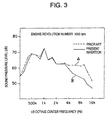
- Fig. 3 shows a result of measurement of sound pressure levels of respective frequencies by a 1/3 octave analyzer with respect to exhaust sound in an engine revolution number of 3000 rpm when using the conventional muffler provided with the simply planar inner plates and using the muffler provided with the inner plates 4, 5 with the convex portions 15 and concave portions 16 formed thereon as shown in Figs. 2A to 2C. according to the present invention.
- the conventional muffler showed property A in Fig. 3, while the muffler of the present invention showed property B.
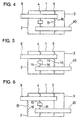
- both outer plates 2, 3 provided with the aforementioned convex portions 15 and concave portions 16 are disposed opposite to both inner plates 4, 5 provided with the convex portions 15 and concave portions 16 to constitute the muffler, but in another embodiment of Fig. 4, one inner plate 5 may be provided with the aforementioned convex portions 15 and concave portions 16, or as in still another embodiment shown in Fig. 5, the inner plates 4, 5 disposed opposite to each other may be provided with the convex portions 15 and concave portions 16, further as in another embodiment shown in Fig. 6, the convex portions 15 and concave portions 16 may be provided on the outer plate 2 (or 3) and the inner plate 4 (or 5) disposed opposite to each other. Furthermore, it is optional to provide the convex portions 15 and concave portions 16 on either one of the aforementioned plates.
- the exhaust noise of the vehicle the harsh high-frequency component exhaust noise is reduced as compared with the conventional muffler, and the discomfort by the exhaust noise can be moderated. Furthermore, since the exhaust noise is further diffusely reflected by the convex and concave portions, the exhaust noise can further be reduced. Additionally, the plate surface rigidity is enhanced, and the abnormal noise and breakage by the plate vibration can also be prevented.
- the aforementioned exhaust noise can further be reduced.
- the pipe vibration can be depressed.
- the convex portions and concave portions on the opposite outer plate and the inner plate or the opposite inner plates, the aforementioned exhaust noise reducing effect can further be enhanced.
Landscapes
- Engineering & Computer Science (AREA)
- Chemical & Material Sciences (AREA)
- Combustion & Propulsion (AREA)
- Mechanical Engineering (AREA)
- General Engineering & Computer Science (AREA)
- Exhaust Silencers (AREA)
Description
- The present invention relates to a muffler.
- As a conventional internal combustion engine muffler, a muffler has been generally employed which is, as shown in Fig. 7, constituted by dividing a main body formed of a
shell 101 andouter plates expansion chambers resonance chamber 108 byinner plates inlet pipe 109 for introducing exhaust gas, anoutlet pipe 110 for discharging the exhaust gas to the atmosphere, and aninner pipe 111 for connecting the respective chambers to each other. - Moreover, as shown as the
outer plates inner plates connection holes 112 for passing the respective pipes are formed in a flat plate molded by press processing, and linear ribs (beads) 114 are formed in aplane portion 113 excluding theconnection holes 112, so as to restrain surface vibration of theouter plates inner plates - In the
outer plates inner plates plane portion 113 except theribs 114 is formed in a broad range, in parallel and opposite arrangement of these plates, a high frequency component of the exhaust noise is reflected to thebroad plane portion 113 to reciprocate many times between the opposite plates. Therefore, with respect to the exhaust noise with a specified frequency, sharp resonance occurs, reverberation time is lengthened, and further a flutter echo phenomenon occurs, which causes a secondary noise in the muffler. - Moreover, when the
rib 114 is linearly formed as described above, diffused reflection of exhaust noise occurs in a direction perpendicular to a linear direction of therib 114, but no irregular reflection occurs in the linear direction. Therefore, the reflected high frequency component of exhaust noise fails to sufficiently interfere with each other, and secondary noise is insufficiently restrained. - Document JP2 040 914 U shows another muffler which has an inner dividing plate having adjacent convex and concave portions.
- Therefore, an object of the present invention is to provide a muffler in which by enhancing vibration-damping effects of outer and inner plates, and by effectively utilizing a limited plate area to form many irregular reflection elements, the exhaust noise can be reduced as compared with the aforementioned conventional plate.
- In order to attain the aforementioned objects, according to the present invention, there is provided a muffler in which an inside is divided into a plurality of chambers by at least an inner plate, a plurality of dot-shaped convex and concave portions are provided in at least one of the inner plate and/or the outer plate, the convex portions and the concave portions are alternately arranged in a pattern on said one surface such that one concave portion is surrounded by plural convex portions and one convex portion is surrounded by concave portions and adjacent convex portions and concave portions are connected by a curved surface.
- In the present invention, since high frequency components of the exhaust noise having hit the dot-shaped convex and concave portions are diffusely reflected to interfere with each other in all spatial directions, the secondary noise is restrained, and the exhaust noise is reduced as compared with the conventional art. Furthermore, since the convex and concave portions are alternately disposed and connected to each other by the curved surfaces, plate surface rigidity is enhanced, and abnormal noise and breakage by plate vibration can also be prevented.
- Moreover, in the present invention, the convex and concave portions may be disposed substantially on the entire surface of the plate.
- Thereby, the aforementioned irregular reflection is performed substantially on the entire surface of the plate, and the exhaust noise is further reduced.
- Furthermore, in the present invention, a burring portion for passing a pipe can also be disposed on the convex or concave portion.
- Pipe vibration is restrained by providing the burring portion without deteriorating the plate surface rigidity.
- Moreover, in the present invention, the convex and concave portions may be provided on the outer and inner plates disposed opposite to each other or the inner plates disposed opposite to each other.
- By disposing the plates with the convex and concave portions disposed thereon opposite to each other, the aforementioned reduction effect of the exhaust noise is further enhanced.
-
- Fig. 1 is a schematic sectional view showing an embodiment of a muffler according to the present invention in which convex and concave portions are provided on all plates.
- Fig. 2A is a front view of an inner plate showing an embodiment of an arrangement state of the convex and concave portions of the present invention, Fig. 2B is a sectional view taken along a line IIB-IIB in Fig. 2A, and Fig. 2C is a sectional view taken along a line IIC-IIC in Fig. 2A.
- Fig. 3 is a diagram showing muffling properties of the muffler using the plate of the embodiment according to the present invention and a conventional muffler.
- Fig. 4 is a schematic sectional view of a muffler in which convex and concave portions are provided on one inner plate in another embodiment according to the present invention.
- Fig. 5 is a schematic sectional view of a muffler in which the convex and concave portions are provided on two opposite inner plates in still another embodiment according to the present invention.
- Fig. 6 is a schematic sectional view of a muffler in which convex and concave portions are provided on outer and inner plates disposed opposite to each other in further embodiment according to the present invention.
- Fig. 7 is a schematic sectional view showing a conventional muffler.
- Fig. 8A is a front view of the inner plate in the muffler of Fig. 7, and Fig. 8B is a sectional view taken along a line VIIIB-VIIIB in Fig. 8A.
- Embodying modes according to the present invention will be described based on embodiments shown in Figs. 1 to 6.
- Fig. 1 shows an embodiment of a muffler in which the present invention is applied to outer and inner plates.
- In Fig. 1, a main body formed by a
shell 1 andouter plates chambers 6, 7, 8 by twoinner plates inlet pipe 9, anoutlet pipe 10, and aninner pipe 11 are passed through the plates and arranged as shown in Fig. 1. The respective members are formed of metal plates. - The
outer plates inner plates inner plate 4 as an example with reference to Figs. 2A to 2C. - Fig. 2A is a front view of the
inner plate 4, and aconnection hole 12 in theinlet pipe 9,connection hole 13 in theoutlet pipe 10 andconnection hole 14 in theinner pipe 11 are formed through the inner plate. - The entire surface excluding the
respective connection holes 12 to 14 and an outer peripheral portion of theplate 4 is dotted with hemisphericalconvex portions 15 and hemisphericalconcave portions 16 formed by press processing with respect to one surface (front surface) of theinner plate 4. Additionally, in Fig. 2A theconvex portion 15 is shown by a white circle, and theconcave portion 16 is shown by a black circle. - In these
convex portions 15 andconcave portions 16, oneconvex portion 15 is surrounded with fourconcave portions 16, and oneconcave portion 16 is surrounded with fourconvex portions 15. Furthermore, theconvex portion 15 andconcave portion 16, theconvex portion 15 and convexportion 15, or theconcave portion 16 andconcave portion 16, which are disposed adjacent to each other, are connected to each other by a smooth curved surface as shown in Figs. 2B, 2C. Furthermore, around theconnection holes 12 to 14,burrings 19 for making the pipe pass through are positioned on theconvex portions 15 or theconcave portions 16 and formed in a bent shape. Additionally, theconvex portion 15 andconcave portion 16 may be provided on the entire surface of the plate, but in the embodiment of Fig. 2A, aplane portion 20 for pressing a jig onto the outer peripheral portion of theplate 4 during insertion of theplate 4 into theshell 1 in a muffler assembly process is provided on the outer peripheral portion of theplate 4. - A
flange 18 for engagement with theshell 1 is formed in a bent shape around theinner plate 4. - As described above, since both the dot-shaped
convex portions 15 and the dot-shapedconcave portions 16 are provided, high frequency components of the exhaust noise having hit theconvex portions 15 andconcave portions 16 are diffusely reflected in all spatial directions to interfere, secondary noise is therefore restrained, and the exhaust noise (ejection noise and emission noise from the muffler) is reduced as compared with the conventional muffler. Particularly, for an exhaust noise of a vehicle, a harsh high frequency component exhaust noise is mainly reduced, and a feeling of discomfort in the exhaust noise is relieved. - Furthermore, by forming the
convex portion 15 and theconcave portion 16 in the dot shapes as described above, these portions can be arranged with a high density, and by the high-density arrangement, the irregular reflection and interference of the high frequency component are sufficiently caused so that the exhaust noise can further be reduced. - Additionally, by connecting the
convex portion 15 to theconcave portion 16 via the curved surface as described above, theconvex portion 15 is smoothly connected to theconcave portion 16. Therefore, since a small-rigidity plane heretofore present between the portions can be removed, the surface rigidity of theplates 2 to 5 is enhanced, and abnormal noise and breakage by vibration of theplates 2 to 5 can further be prevented. - Moreover, as described above, there is an effect that pipe vibration is restrained by providing the
burring portion 19 on theconvex portion 15 or theconcave portion 16. - Furthermore, the exhaust noise of a broad high-frequency band can be reduced by setting the
convex portion 15 to be high, but the height of theconvex portion 15 alone is limited by forming limit. However, by alternately arranging theconvex portion 15 andconcave portion 16 close to each other as described above, an effect similar to the effect obtained by increasing the height of theconvex portion 15 can be obtained and processing can be facilitated. - Additionally, the
convex portions 15 andconcave portions 16 may be provided substantially on the entire surface of theplate 4. - When the
convex portions 15 andconcave portions 16 are provided substantially on the entire surface of the plate in this manner, the aforementioned respective effects are further enlarged. - Moreover, the
convex portion 15 and theconcave portion 16 in the aforementioned embodiment are formed in the hemispherical shapes, but theconvex portion 15 and theconcave portion 16 may be formed in a semielliptical shape, a conical shape, or a pyramidal shape. - Furthermore, in the aforementioned embodiment, a size of the
convex portion 15 may differ from the size of theconcave portion 16. - Additionally, the present invention may be applied to the inner plate in which a large number of small holes are formed to rectify an exhaust gas flow and silence the noise thereof.
- Moreover, a ratio of the
convex portion 15 to the entire surface of the plate, or the ratio of theconcave portion 16 thereto, and further the ratio between theconvex portion 15 andconcave portion 16 are optionally set in accordance with the muffler constitution, reverberation time of the respective chambers, and the like. - Fig. 3 shows a result of measurement of sound pressure levels of respective frequencies by a 1/3 octave analyzer with respect to exhaust sound in an engine revolution number of 3000 rpm when using the conventional muffler provided with the simply planar inner plates and using the muffler provided with the
inner plates convex portions 15 andconcave portions 16 formed thereon as shown in Figs. 2A to 2C. according to the present invention. - As the measurement result, the conventional muffler showed property A in Fig. 3, while the muffler of the present invention showed property B.
- As apparent from the measurement result, the exhaust noise of the high frequency component was reduced in the muffler of the present invention.
- In the embodiment of Fig. 1, both
outer plates convex portions 15 andconcave portions 16 are disposed opposite to bothinner plates convex portions 15 andconcave portions 16 to constitute the muffler, but in another embodiment of Fig. 4, oneinner plate 5 may be provided with the aforementionedconvex portions 15 andconcave portions 16, or as in still another embodiment shown in Fig. 5, theinner plates convex portions 15 andconcave portions 16, further as in another embodiment shown in Fig. 6, theconvex portions 15 andconcave portions 16 may be provided on the outer plate 2 (or 3) and the inner plate 4 (or 5) disposed opposite to each other. Furthermore, it is optional to provide theconvex portions 15 andconcave portions 16 on either one of the aforementioned plates. - Even when one plate is provided with the
convex portions 15 andconcave portions 16 as shown in Fig. 4, the aforementioned effect is fulfilled as compared with the conventional muffer, but the effect is further enlarged by providing theconvex portions 15 andconcave portions 16 on the opposite plates. - As described above, according to the present invention, particularly, as the exhaust noise of the vehicle the harsh high-frequency component exhaust noise is reduced as compared with the conventional muffler, and the discomfort by the exhaust noise can be moderated. Furthermore, since the exhaust noise is further diffusely reflected by the convex and concave portions, the exhaust noise can further be reduced. Additionally, the plate surface rigidity is enhanced, and the abnormal noise and breakage by the plate vibration can also be prevented.
- Moreover, in the present invention, by providing the convex portions or the concave portions substantially on the entire surface of the plate, the aforementioned exhaust noise can further be reduced.
- Furthermore, by providing the burring portion for passing the pipe on the convex portion or the concave portion, the pipe vibration can be depressed.
- Additionally, by providing the convex portions and concave portions on the opposite outer plate and the inner plate or the opposite inner plates, the aforementioned exhaust noise reducing effect can further be enhanced.
Claims (8)
- A muffler comprising a main body formed by a shell (1) and two outer plates (2, 3), wherein an inside is divided into a plurality of chambers by at least an inner plate (4, 5),
characterized in that
at least one of said outer plates and/or said at least one inner plate is provided with plural dot-shaped convex portions (15) and plural dot-shaped concave portions (16) with respect to one surface of said at least one plate and arranged adjacent each other, said convex portions (15) and said concave portions (16) are alternately arranged in a pattern on said one surface such that one concave portion (16) is surrounded by plural convex portions (15) and one convex portion (15) is surrounded by concave portions (16), wherein adjacent concave portions (16) and convex portions (15) are connected to each other by a curved surface. - The muffler according to claim 1, wherein said convex portions (15) and concave portions (16) are provided substantially on the entire surface of the at least one plate.
- The muffler according to claim 1, wherein a burring portion (19) for passing a pipe (9, 10, 11) is provided on the convex portions (15) or the concave portions (16).
- The muffler according to claim 2, wherein a burring portion (19) for passing a pipe (9, 10, 11) is provided on the convex portions (15) or the concave portions (16).
- The muffler according to claim 1, wherein the convex portions (15) and the concave portions (16) are provided on the outer plate (2, 3) and the at least one inner plate (4, 5) disposed opposite to each other or the inner plates (4, 5) disposed opposite to each other.
- The muffler according to claim 2, wherein the convex portions (15) and the concave portions (16) are provided on the outer plate (2, 3) and the at least one inner plate (4, 5) disposed opposite to each other or the inner plates (4, 5) disposed opposite to each other.
- The muffler according to claim 3, wherein the convex portions (15) and the concave portions (16) are provided on the outer plate (2, 3) and the at least one inner plate (4, 5) disposed opposite to each other or the inner plates (4, 5) disposed opposite to each other.
- The muffler according to claim 4, wherein the convex portions (15) and the concave portions (16) are provided on the outer plate (2, 3) and the at least one inner plate (4, 5) disposed opposite to each other or the inner plates (4, 5) disposed opposite to each other.
Applications Claiming Priority (3)
| Application Number | Priority Date | Filing Date | Title |
|---|---|---|---|
| JP14393298 | 1998-05-26 | ||
| JP10143932A JP2962706B1 (en) | 1998-05-26 | 1998-05-26 | Silencer |
| PCT/JP1999/002771 WO1999061762A1 (en) | 1998-05-26 | 1999-05-26 | Silencer |
Publications (3)
| Publication Number | Publication Date |
|---|---|
| EP1088968A1 EP1088968A1 (en) | 2001-04-04 |
| EP1088968A4 EP1088968A4 (en) | 2004-08-11 |
| EP1088968B1 true EP1088968B1 (en) | 2006-02-08 |
Family
ID=15350439
Family Applications (1)
| Application Number | Title | Priority Date | Filing Date |
|---|---|---|---|
| EP99922499A Expired - Lifetime EP1088968B1 (en) | 1998-05-26 | 1999-05-26 | Silencer |
Country Status (5)
| Country | Link |
|---|---|
| US (1) | US6427802B1 (en) |
| EP (1) | EP1088968B1 (en) |
| JP (1) | JP2962706B1 (en) |
| DE (1) | DE69929784T2 (en) |
| WO (1) | WO1999061762A1 (en) |
Families Citing this family (13)
| Publication number | Priority date | Publication date | Assignee | Title |
|---|---|---|---|---|
| JP4392592B2 (en) * | 2003-12-12 | 2010-01-06 | トヨタ自動車株式会社 | Exhaust silencer |
| JP4661634B2 (en) * | 2006-03-03 | 2011-03-30 | トヨタ自動車株式会社 | Muffler structure for vehicles |
| US7905322B2 (en) * | 2006-08-10 | 2011-03-15 | Woodrow Woods | Marine muffler with angularly disposed internal baffle |
| US7581620B2 (en) * | 2006-08-10 | 2009-09-01 | Woodrow Woods | Marine muffler with angularly disposed internal baffle |
| DE102009009168A1 (en) * | 2009-02-16 | 2010-08-19 | Man Turbo Ag | Silencer for a flow or piston machine |
| US8591208B2 (en) * | 2009-06-24 | 2013-11-26 | Southwest Research Institute | Multi-frequency pulsation absorber at cylinder valve cap |
| KR101251728B1 (en) * | 2010-09-07 | 2013-04-05 | 현대자동차주식회사 | Car silencer |
| JP5532043B2 (en) * | 2010-12-24 | 2014-06-25 | トヨタ自動車株式会社 | Vehicle silencer |
| EP2518286B1 (en) * | 2011-04-28 | 2015-07-15 | Eberspächer Exhaust Technology GmbH & Co. KG | Exhaust silencer for motor vehicles |
| JP5878772B2 (en) * | 2012-02-08 | 2016-03-08 | 川崎重工業株式会社 | Exhaust muffler |
| JP6480741B2 (en) * | 2015-02-04 | 2019-03-13 | 株式会社神戸製鋼所 | Silencer |
| DE102015108495A1 (en) * | 2015-05-29 | 2016-12-01 | Eberspächer Exhaust Technology GmbH & Co. KG | Exhaust silencer for transverse installation in a vehicle |
| JP7485518B2 (en) * | 2020-02-21 | 2024-05-16 | フタバ産業株式会社 | scarf |
Family Cites Families (19)
| Publication number | Priority date | Publication date | Assignee | Title |
|---|---|---|---|---|
| GB748943A (en) * | 1953-03-25 | 1956-05-16 | Mcfarlane Harrison Ltd | Improvements in or relating to exhaust silencers |
| US3009530A (en) * | 1960-01-21 | 1961-11-21 | Laco Oil Burner Co Inc | Exhaust device |
| US3232374A (en) * | 1963-08-09 | 1966-02-01 | Walker Mfg Co | Ceramic coated muffler with liquid flow gaps between partitions and shell |
| US3675734A (en) * | 1971-09-10 | 1972-07-11 | Blatt Leland F | Silencer with frequency separating and modulating baffle |
| JPS49128144A (en) | 1973-04-18 | 1974-12-07 | ||
| JPS49129034A (en) | 1973-04-20 | 1974-12-10 | ||
| JPS6038114A (en) | 1983-08-12 | 1985-02-27 | Yokohama Rubber Co Ltd:The | Sealer for kneader |
| JPS6038114U (en) * | 1983-08-24 | 1985-03-16 | 日産自動車株式会社 | Automobile exhaust silencer |
| JPS6279918A (en) | 1985-10-01 | 1987-04-13 | Mitsubishi Electric Corp | Retreat control device for electric discharge machine |
| JPS6279918U (en) * | 1985-11-08 | 1987-05-22 | ||
| US4673058A (en) * | 1986-05-09 | 1987-06-16 | G Enterprises Limited | High performance automotive muffler |
| JPH0240914A (en) | 1988-07-30 | 1990-02-09 | Nec Corp | Formation of pattern |
| JPH0240914U (en) * | 1988-09-14 | 1990-03-20 | ||
| DE59100068D1 (en) * | 1990-04-30 | 1993-05-06 | Beidl Christian | EXHAUST MUFFLER, ESPECIALLY FOR TWO-STROKE COMBUSTION ENGINES WITH POST-ORDERED CATALYST. |
| JP2952790B2 (en) | 1991-04-12 | 1999-09-27 | 本田技研工業株式会社 | Engine silencer |
| JP2578330Y2 (en) * | 1992-02-10 | 1998-08-13 | 株式会社共立 | Exhaust muffler structure of internal combustion engine |
| JPH0716673A (en) * | 1993-06-30 | 1995-01-20 | Toshiomi Hayashi | Combined structure with orthogonally crossing thin plate and thin wall tube and its manufacture |
| US5563385A (en) * | 1995-03-07 | 1996-10-08 | Ap Parts Manufacturing Company | Stamp formed muffler with siphon tube |
| JPH09291819A (en) * | 1996-04-26 | 1997-11-11 | Calsonic Corp | Structure for fixing muffler pipe to baffle plate |
-
1998
- 1998-05-26 JP JP10143932A patent/JP2962706B1/en not_active Expired - Lifetime
-
1999
- 1999-05-26 DE DE69929784T patent/DE69929784T2/en not_active Expired - Lifetime
- 1999-05-26 WO PCT/JP1999/002771 patent/WO1999061762A1/en not_active Ceased
- 1999-05-26 US US09/701,137 patent/US6427802B1/en not_active Expired - Lifetime
- 1999-05-26 EP EP99922499A patent/EP1088968B1/en not_active Expired - Lifetime
Also Published As
| Publication number | Publication date |
|---|---|
| JP2962706B1 (en) | 1999-10-12 |
| WO1999061762A1 (en) | 1999-12-02 |
| EP1088968A1 (en) | 2001-04-04 |
| US6427802B1 (en) | 2002-08-06 |
| DE69929784D1 (en) | 2006-04-20 |
| EP1088968A4 (en) | 2004-08-11 |
| JPH11336526A (en) | 1999-12-07 |
| DE69929784T2 (en) | 2006-11-09 |
Similar Documents
| Publication | Publication Date | Title |
|---|---|---|
| US6427802B1 (en) | Muffler | |
| CA2069040C (en) | Stamp formed muffler with in-line expansion chamber and arcurately formed effective flow tubes | |
| US7219764B1 (en) | Exhaust muffler | |
| WO2001065084A1 (en) | Stamp-formed muffler | |
| US20030101030A1 (en) | Optimal rib design method for exhaust components | |
| JPH07332077A (en) | Connector for connecting two upstream exhaust pipes of unequal length to the downstream exhaust pipe | |
| JPH10252445A (en) | Silencer | |
| US4671381A (en) | Linear muffler shockwave suppressor | |
| EP0636780A1 (en) | Noise suppression liner for jet engines | |
| CA1198987A (en) | Muffler | |
| EP1597460B1 (en) | Muffler | |
| JPS5918183Y2 (en) | Noise prevention wall material for structures | |
| CN100366868C (en) | silencer | |
| JPH0557308U (en) | Exhaust pipe structure of engine silencer | |
| US20060283661A1 (en) | Silencer | |
| JPH11324667A (en) | Exhaust system structure of internal combustion engine and method of manufacturing exhaust pipe used for exhaust system structure of internal combustion engine | |
| JPH03246312A (en) | Silencer for automobile | |
| JP2004245052A (en) | Muffler for internal combustion engine | |
| JP2009209854A (en) | Muffler | |
| CN224200725U (en) | Exhaust heat insulation assembly and vehicle | |
| JP4037572B2 (en) | Silencer | |
| CN223075682U (en) | Muffler of air compressor and air compressor | |
| CN223104771U (en) | Compressors and refrigeration equipment | |
| CN223482746U (en) | Air inlet cone shell | |
| CN223482741U (en) | Intake cone assembly |
Legal Events
| Date | Code | Title | Description |
|---|---|---|---|
| PUAI | Public reference made under article 153(3) epc to a published international application that has entered the european phase |
Free format text: ORIGINAL CODE: 0009012 |
|
| 17P | Request for examination filed |
Effective date: 20001123 |
|
| AK | Designated contracting states |
Kind code of ref document: A1 Designated state(s): DE FR GB IT |
|
| RIC1 | Information provided on ipc code assigned before grant |
Ipc: 7F 01N 1/06 B Ipc: 7F 01N 1/02 B Ipc: 7F 01N 1/08 A |
|
| A4 | Supplementary search report drawn up and despatched |
Effective date: 20040628 |
|
| 17Q | First examination report despatched |
Effective date: 20041104 |
|
| GRAP | Despatch of communication of intention to grant a patent |
Free format text: ORIGINAL CODE: EPIDOSNIGR1 |
|
| GRAS | Grant fee paid |
Free format text: ORIGINAL CODE: EPIDOSNIGR3 |
|
| GRAA | (expected) grant |
Free format text: ORIGINAL CODE: 0009210 |
|
| AK | Designated contracting states |
Kind code of ref document: B1 Designated state(s): DE FR GB IT |
|
| REG | Reference to a national code |
Ref country code: GB Ref legal event code: FG4D |
|
| REF | Corresponds to: |
Ref document number: 69929784 Country of ref document: DE Date of ref document: 20060420 Kind code of ref document: P |
|
| ET | Fr: translation filed | ||
| PLBE | No opposition filed within time limit |
Free format text: ORIGINAL CODE: 0009261 |
|
| STAA | Information on the status of an ep patent application or granted ep patent |
Free format text: STATUS: NO OPPOSITION FILED WITHIN TIME LIMIT |
|
| 26N | No opposition filed |
Effective date: 20061109 |
|
| REG | Reference to a national code |
Ref country code: FR Ref legal event code: PLFP Year of fee payment: 18 |
|
| REG | Reference to a national code |
Ref country code: FR Ref legal event code: PLFP Year of fee payment: 19 |
|
| REG | Reference to a national code |
Ref country code: FR Ref legal event code: PLFP Year of fee payment: 20 |
|
| PGFP | Annual fee paid to national office [announced via postgrant information from national office to epo] |
Ref country code: DE Payment date: 20180522 Year of fee payment: 20 |
|
| PGFP | Annual fee paid to national office [announced via postgrant information from national office to epo] |
Ref country code: FR Payment date: 20180522 Year of fee payment: 20 Ref country code: IT Payment date: 20180530 Year of fee payment: 20 |
|
| PGFP | Annual fee paid to national office [announced via postgrant information from national office to epo] |
Ref country code: GB Payment date: 20180518 Year of fee payment: 20 |
|
| REG | Reference to a national code |
Ref country code: DE Ref legal event code: R071 Ref document number: 69929784 Country of ref document: DE |
|
| REG | Reference to a national code |
Ref country code: GB Ref legal event code: PE20 Expiry date: 20190525 |
|
| PG25 | Lapsed in a contracting state [announced via postgrant information from national office to epo] |
Ref country code: GB Free format text: LAPSE BECAUSE OF EXPIRATION OF PROTECTION Effective date: 20190525 |