EP0636780A1 - Noise suppression liner for jet engines - Google Patents
Noise suppression liner for jet engines Download PDFInfo
- Publication number
- EP0636780A1 EP0636780A1 EP94304367A EP94304367A EP0636780A1 EP 0636780 A1 EP0636780 A1 EP 0636780A1 EP 94304367 A EP94304367 A EP 94304367A EP 94304367 A EP94304367 A EP 94304367A EP 0636780 A1 EP0636780 A1 EP 0636780A1
- Authority
- EP
- European Patent Office
- Prior art keywords
- honeycomb
- tubular
- cell
- noise suppression
- cells
- Prior art date
- Legal status (The legal status is an assumption and is not a legal conclusion. Google has not performed a legal analysis and makes no representation as to the accuracy of the status listed.)
- Withdrawn
Links
Images

Classifications
-
- F—MECHANICAL ENGINEERING; LIGHTING; HEATING; WEAPONS; BLASTING
- F02—COMBUSTION ENGINES; HOT-GAS OR COMBUSTION-PRODUCT ENGINE PLANTS
- F02K—JET-PROPULSION PLANTS
- F02K1/00—Plants characterised by the form or arrangement of the jet pipe or nozzle; Jet pipes or nozzles peculiar thereto
- F02K1/78—Other construction of jet pipes
- F02K1/82—Jet pipe walls, e.g. liners
- F02K1/827—Sound absorbing structures or liners
-
- G—PHYSICS
- G10—MUSICAL INSTRUMENTS; ACOUSTICS
- G10K—SOUND-PRODUCING DEVICES; METHODS OR DEVICES FOR PROTECTING AGAINST, OR FOR DAMPING, NOISE OR OTHER ACOUSTIC WAVES IN GENERAL; ACOUSTICS NOT OTHERWISE PROVIDED FOR
- G10K11/00—Methods or devices for transmitting, conducting or directing sound in general; Methods or devices for protecting against, or for damping, noise or other acoustic waves in general
- G10K11/16—Methods or devices for protecting against, or for damping, noise or other acoustic waves in general
- G10K11/172—Methods or devices for protecting against, or for damping, noise or other acoustic waves in general using resonance effects
Definitions
- This disclosure relates to a tubular component, such as an exhaust shroud, formed as a part of a noise suppression system for an aircraft jet engine.
- the noise produced by a jet engine is composed basically of: (a) a broadband energy related to the jet exhaust velocity, and (b) a narrowband tone energy produced by the turbo-machinery of the jet engine itself. If an exhaust shroud extending aft of the engine can be made to absorb and dissipate the low frequency energy produced by the jet engine, then a significant portion of the overall noise produced by an aircraft jet engine can be eliminated.
- a typical method of providing sound absorption material is the use of a honeycomb panel. Any sound absorption material used in a jet engine noise suppression system must be capable of withstanding the high temperatures encountered in the engine exhaust and thus must be made of metal, the preferred metal being stainless steel.
- Stainless steel honeycomb panels are typically produced with a honeycomb core with a planar material covering one or both sides. When using such planar honeycomb panels it is necessary to carve them into arcuate portions to fit inside the usual tubular exhaust shroud. The problem is that this method produces unequal individual cell sizes and cell alignments as measured with reference to the exhaust shroud tubular axis.
- honeycomb material that has irregular cell heights and cell alignments reduces the effectiveness of sound absorption. Absorption of a relatively low frequency band is required to effectively dissipate the sound energy tone produced by a jet engine. In other words, the sound absorption characteristics of previously used honeycomb sound absorption material has not maximized the noise reduction potential of a noise reduction system for use with a jet engine.
- This invention pertains to a tubular component, such as an exhaust shroud used in a system for noise abatement of a jet aircraft engine. More particularly, the invention relies to an exhaust shroud used in a jet engine noise suppression system that provides a tubular component through which thrust producing jet engine exhaust gases pass. These jet engine gases inherently have a low frequency band of sound energy produced by the jet engine itself. If this low frequency sound produced energy is not absorbed in some way, it becomes a significant component of the overall noise generated by the engine. By providing a sound absorption material within the tubular component (such as an exhaust shroud) capable of absorbing the low frequency sound produced energy, the total resultant noise of the jet engine can be reduced.
- a sound absorption material within the tubular component such as an exhaust shroud
- An effective and a preferred type of sound absorption material is a panel having a honeycomb core formed of thin metal strips bent and welded together to form contiguous honeycomb cells.
- Honeycomb panels are typically formed in flat sheets.
- a honeycomb core can be bent into a curve if the depth of the honeycomb core is relatively small, such as one inch or less.
- honeycomb core material requires honeycomb cells of depth greater than one inch, as much as five or six inches, with a depth of two or three inches being typical.
- honeycomb sound absorption material with significant depths, such as more than one inch, and particularly two or three inches, have employed flat honeycomb panels of this depth that are machined, after the panels are manufactured, to required circumferential contours to fit within a tubular exhaust shroud.
- This technique has met with less than complete success since such arrangement provides a honeycomb sound absorption material wherein the honeycomb cells are of an irregular configuration.
- the present invention solves the problem of the known type of deep cell honeycomb sound absorption systems for use in exhaust shrouds by providing an acoustic liner formed of a honeycomb metallic core with contiguous hexagonal honeycomb cells arranged such that the cells each have a longitudinal axis that extends perpendicular to the tubular axis of the exhaust shroud. Each cell is symmetrical with respect to the other cells in the sound absorption system.
- the typical depth of the cells which depends upon the sound frequency being absorbed, is two or three inches but in some applications may be five or six inches.
- the typical dimension of the cells measured from sidewall to sidewall at the outer circumferential periphery of the tubular sound absorption material is about 3/8 inch to 1/2 inch.
- an acoustical liner for support within a structural shell forming an exhaust shroud, the acoustical liner being formed with a honeycomb metal core of depth exceeding one inch and with hexagonal cell sizes of about 3/8 inch to 1 inch and including a perforated inner skin affixed to the honeycomb metal core.
- the perforated skin provides sound communication within the interior of the hexagonal cores of the honeycomb core but, at the same time, adds strength and rigidity to the acoustic liner and reduces the drag on jet exhaust gases passing through the exhaust shroud.
- Figure 1 is an exploded view of a typical sound absorption system for use in conjunction with a turbofan aircraft engine, a major component of the system being the exhaust shroud component to which this invention pertains.
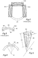
- Figure 2 is an illustration of the prior art showing how relatively thick honeycomb panels, manufactured in the usual planar configuration, can be contoured and then assembled circumferentially in a process of manufacturing a tubular acoustic liner for use in an exhaust shroud.
- Figure 3 is a fragmentary view of the prior art illustrated in Figure 2 showing a segment of a honeycomb core liner that can be used as an acoustic liner in an exhaust shroud of the type formed of a block of planar honeycomb core and showing that the configuration of the cells vary in length and shape.
- Figure 4 is a partial cross-sectional view diagrammatically illustrating the cells of a honeycomb core acoustic liner arranged according to the principles of this invention wherein each of the cells of the acoustic liner has a longitudinal axis that is perpendicular to the exhaust shroud tubular axis.
- Figure 5 is a diagrammatic illustration of a single cell of a honeycomb core acoustic liner illustrating the general appearance of a cell, however, in this illustration the dimensions are not in proportion, in that the illustration shows the width of the typical cell out of proportion to the typical length.
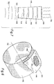
- Figure 6 is a fragmentary view of an acoustic liner as employed in an exhaust shroud as taken along the line 6-6 of Figure 1.
- Figure 6 shows a short length section of an acoustic liner that employs a perforated inner skin and with the outer skin of the acoustic liner being broken away to show the configuration of the honeycomb cells.
- Figure 7 is a diagrammatic illustration of a cross-section of a cell showing the opposed sidewalls and inner and outer skins, the inner skin being perforated to provide an entry for sound into the cell and showing sound waves as they travel within the cell.
- FIG. 1 is an illustration of one method of providing sound abatement for a turbofan aircraft engine.
- a typical turbofan engine is indicated by the numeral 10 having an exhaust end 12.
- the engine 10 functions by exhausting gases at exhaust end 12 at thrust producing velocities. Jet aircraft engines are extremely effective for producing thrust, however, the heated exhaust gases passing out the exhaust end produce high levels of noise, and the aircraft industry has been working to abate the noise produced by engines.
- the noise produced by the exhaust gases passing out exhaust end 12 of a jet engine 10 are composed basically of, first, a low frequency energy relating to the exhaust gas velocity and, second, to a narrowband tone energy produced by the turbo-machinery of the jet engine itself.
- This invention is concerned primarily with the low frequency energy produced by the exhaust gas of the jet engines.
- Figure 1 shows components that can be employed to help reduce the noise generated by an engine, including an internal flow mixer 14, an exhaust nozzle 16, and an exhaust shroud 18.
- the exhaust shroud is the final element through which the jet engine thrust producing gases pass before exiting to the atmosphere.
- Exhaust shroud 18 includes an acoustic liner 20 designed to absorb sound of the exhaust gases and to absorb the band tone energy produced by the turbo-machinery of jet engine 10.
- This invention is concerned entirely with the exhaust shroud 18 and particularly the acoustic liner 20 therein, the other components of Figure 1 being illustrated merely to indicate a typical environment in which an exhaust shroud having acoustic liner 20 therein can be employed.
- the acoustic liner 20 can be formed in various ways, however, one method which has proven satisfactory and which is deemed to be the preferred method of providing acoustic liner 20 employs the use of a liner made with a honeycomb metallic core.
- the use of honeycomb panels is well known in the aircraft industry and the use of a honeycomb core has been previously employed in connection with exhaust shrouds in an effort to reduce noise.
- Figures 2 and 3 are illustrative of the prior art and show methods whereby flat panels of honeycomb core material can be employed in manufacturing a honeycomb core.
- Figure 2 shows three planar honeycomb deep cell panels 22A, 22B and 22C arranged in an outline 24 of a tubular acoustic liner as can be employed in liner 20 of Figure 1.
- the outline 24 superimposed over the planar honeycomb panels 22A, 22B and 22C illustrates how such panels must be shaped so that they can be assembled together in the formation of a tubular acoustic liner.
- Figure 2 shows only three of the planar honeycomb panels, it being apparent that more than these three are required to provide a complete circumferential tubular acoustic liner.
- FIG 3 is another illustration of the prior art showing the honeycomb material that is obtained from shaping a planar honeycomb panel 22B.
- the panel includes an inner skin 26 and outer skin 28 with a honeycomb core therebetween defining a plurality of individual honeycomb cells 30.
- an acoustic liner formed in this method provides honeycomb cells 30 that are irregular in configuration.
- the honeycomb cells vary in depth and cross-sectional shape and, therefore, the cells are inherently tuned to absorb different sound frequencies.
- providing a honeycomb of this construction formed of planar honeycomb panels does not lend itself to the formation of an acoustic liner capable of effectively absorbing a narrow band of low frequency energy.
- the improved acoustic liner of this invention is illustrated in Figures 4 through 7.
- the basic concept of the improved liner is the employment of a honeycomb core that is constructed so that each cell of the core is arranged radially about the tubular axis of a tubular component of a jet aircraft engine sound abatement system, such as the exhaust shroud 18 of Figure 1.
- a tubular axis of such tubular component is illustrated by the numeral 32 in Figures 4, 5 and 6.
- Each of the cells 34 of the improved acoustic liner 20 has an imaginary longitudinal axis 38 extending centrally within the interior of each cell and extending in the direction of the length thereof.
- each cell 34 is arranged to be perpendicular to tubular axis 32 of the tubular exhaust shroud. In this way each cell 34 is uniform in its size, including its width and length, and in its orientation relative to the exhaust gases passing through the tubular exhaust shroud.
- the sound absorption characteristics of the liner can be carefully tuned to a frequency band which most effectively absorbs the low frequency tone energy produced by a jet engine.
- Figure 5 is an isometric diagrammatic representation of a single cell 34.
- Cell 34 has hexagonal sidewalls and is contiguous to adjacent hexagonal cells.
- Cell 34 has a length 40 that is relatively long compared to its width. Length 40 is at least one inch or greater and as much as six inches, with the typical length being about two to three inches as required for effective sound absorption of the low frequency sound produced by the typical jet engine.
- the width of the cell as measured from opposed hexagonal sidewalls, indicated by the numeral 42, is typically 3/8 inch to 1 inch.
- the cells are relatively small in cross-section compared to their length 40.
- FIG. 6 illustrates a fragmentary section of the improved tubular acoustic liner 20 as would be employed in an exhaust shroud 18, such as taken along the line 6-6 of Figure 1.
- the tubular liner is formed of the honeycomb metallic core having the multiplicity of cells 30 therein with an outer skin 44 and an inner skin 46.
- the outer skin 44 is preferably impervious, or without openings therethrough, whereas inner skin 46 is preferably perforated as illustrated.
- the perforated inner skin 46 allows sound communication with the interior of each cell 30, while outer skin 44 provides a reflective surface within each cell.
- Figure 7 is a cross-sectional diagrammatic illustration of a typical cell 30 showing inner skin 46, outer skin 44 and with cell sidewalls 48.
- the sidewalls 48 define cell 30, sidewalls 48 being hexagonally arranged as shown in Figures 5 and 6.
- inner skin 46 is perforated providing an opening 50 that communicates with the interior of cell 30.
- Sound waves characterized by the low frequency tone energy produced by the jet engines are indicated by the numeral 52. These sound waves pass through opening 50 into the interior of cell 30 where they are reflected by outer skin 44, the reflected waves being indicated by the numeral 54.
- the capture of the sound energy within the individual cells serve to dissipate the sound energy, and by the geometrical arrangement of the cells the dimensions can be selected to match the tonal energy to be absorbed.
- Figure 7 diagrammatically illustrates the manner in which low frequency tone energy produced sound waves 52 are effectively absorbed by cells 30 so that a substantial portion of the tone energy of wave 52 is absorbed, as indicated by the dissipated energy 56.
Landscapes
- Engineering & Computer Science (AREA)
- Physics & Mathematics (AREA)
- Acoustics & Sound (AREA)
- Multimedia (AREA)
- Chemical & Material Sciences (AREA)
- Combustion & Propulsion (AREA)
- Mechanical Engineering (AREA)
- General Engineering & Computer Science (AREA)
- Soundproofing, Sound Blocking, And Sound Damping (AREA)
- Exhaust Silencers (AREA)
Abstract
A tubular component such as an exhaust shroud is provided for use in a noise suppression system for an aircraft jet engine, the tubular component providing an outlet passage for jet engine produced exhaust gases having turbo-machinery produced sound energy superimposed thereon, the tubular component having an outer structural shell (44) with a tubular axis (32) and an acoustic liner supported within the structural shell formed of a tubular honeycomb metallic core, the honeycomb core being formed of thin metallic strips joined into a welded honeycomb arrangement of contiguous hexagonal cells (30). Each of the cells (30) has a longitudinal axis extending perpendicular to the shell tubular axis, each shell being of depth of at least one inch and of a cross-sectional size from wall-to-wall of about 3/8 to 1/2 inch.
Description
- This disclosure relates to a tubular component, such as an exhaust shroud, formed as a part of a noise suppression system for an aircraft jet engine. The noise produced by a jet engine is composed basically of: (a) a broadband energy related to the jet exhaust velocity, and (b) a narrowband tone energy produced by the turbo-machinery of the jet engine itself. If an exhaust shroud extending aft of the engine can be made to absorb and dissipate the low frequency energy produced by the jet engine, then a significant portion of the overall noise produced by an aircraft jet engine can be eliminated.
- The use of a sound absorption material within an exhaust shroud is well known, as exemplified in the following United States Patents: 4,909,346 and 5,060,471.
- A typical method of providing sound absorption material is the use of a honeycomb panel. Any sound absorption material used in a jet engine noise suppression system must be capable of withstanding the high temperatures encountered in the engine exhaust and thus must be made of metal, the preferred metal being stainless steel. Stainless steel honeycomb panels are typically produced with a honeycomb core with a planar material covering one or both sides. When using such planar honeycomb panels it is necessary to carve them into arcuate portions to fit inside the usual tubular exhaust shroud. The problem is that this method produces unequal individual cell sizes and cell alignments as measured with reference to the exhaust shroud tubular axis.
- The use of honeycomb material that has irregular cell heights and cell alignments reduces the effectiveness of sound absorption. Absorption of a relatively low frequency band is required to effectively dissipate the sound energy tone produced by a jet engine. In other words, the sound absorption characteristics of previously used honeycomb sound absorption material has not maximized the noise reduction potential of a noise reduction system for use with a jet engine.
- A method of manufacturing honeycomb core material that can be used in provided honeycomb sound absorptive material to practice the invention of this disclosure is described in United States Patent 5,064,493 issued November 12, 1991. Patent 5,064,493 is incorporated herein by reference.
- This invention pertains to a tubular component, such as an exhaust shroud used in a system for noise abatement of a jet aircraft engine. More particularly, the invention relies to an exhaust shroud used in a jet engine noise suppression system that provides a tubular component through which thrust producing jet engine exhaust gases pass. These jet engine gases inherently have a low frequency band of sound energy produced by the jet engine itself. If this low frequency sound produced energy is not absorbed in some way, it becomes a significant component of the overall noise generated by the engine. By providing a sound absorption material within the tubular component (such as an exhaust shroud) capable of absorbing the low frequency sound produced energy, the total resultant noise of the jet engine can be reduced.
- The inclusion of sound absorption material in an exhaust shroud is a known technique as revealed such as in United States Patent Numbers 4,909,346 and 5,060,471. An effective and a preferred type of sound absorption material is a panel having a honeycomb core formed of thin metal strips bent and welded together to form contiguous honeycomb cells. Honeycomb panels are typically formed in flat sheets. A honeycomb core can be bent into a curve if the depth of the honeycomb core is relatively small, such as one inch or less. However, it has been learned that the most effective sound absorption system employing a honeycomb core material requires honeycomb cells of depth greater than one inch, as much as five or six inches, with a depth of two or three inches being typical. The previous efforts to provide honeycomb sound absorption material with significant depths, such as more than one inch, and particularly two or three inches, have employed flat honeycomb panels of this depth that are machined, after the panels are manufactured, to required circumferential contours to fit within a tubular exhaust shroud. This technique has met with less than complete success since such arrangement provides a honeycomb sound absorption material wherein the honeycomb cells are of an irregular configuration.
- The present invention solves the problem of the known type of deep cell honeycomb sound absorption systems for use in exhaust shrouds by providing an acoustic liner formed of a honeycomb metallic core with contiguous hexagonal honeycomb cells arranged such that the cells each have a longitudinal axis that extends perpendicular to the tubular axis of the exhaust shroud. Each cell is symmetrical with respect to the other cells in the sound absorption system. The typical depth of the cells, which depends upon the sound frequency being absorbed, is two or three inches but in some applications may be five or six inches. The typical dimension of the cells measured from sidewall to sidewall at the outer circumferential periphery of the tubular sound absorption material is about 3/8 inch to 1/2 inch.
- In a preferred arrangement of the invention, an acoustical liner is provided for support within a structural shell forming an exhaust shroud, the acoustical liner being formed with a honeycomb metal core of depth exceeding one inch and with hexagonal cell sizes of about 3/8 inch to 1 inch and including a perforated inner skin affixed to the honeycomb metal core. The perforated skin provides sound communication within the interior of the hexagonal cores of the honeycomb core but, at the same time, adds strength and rigidity to the acoustic liner and reduces the drag on jet exhaust gases passing through the exhaust shroud.
- A better understanding of the invention will be had by reference to the following description of the preferred embodiment and the claims, taken in conjunction with the attached drawings.
- Figure 1 is an exploded view of a typical sound absorption system for use in conjunction with a turbofan aircraft engine, a major component of the system being the exhaust shroud component to which this invention pertains.
- Figure 2 is an illustration of the prior art showing how relatively thick honeycomb panels, manufactured in the usual planar configuration, can be contoured and then assembled circumferentially in a process of manufacturing a tubular acoustic liner for use in an exhaust shroud.
- Figure 3 is a fragmentary view of the prior art illustrated in Figure 2 showing a segment of a honeycomb core liner that can be used as an acoustic liner in an exhaust shroud of the type formed of a block of planar honeycomb core and showing that the configuration of the cells vary in length and shape.
- Figure 4 is a partial cross-sectional view diagrammatically illustrating the cells of a honeycomb core acoustic liner arranged according to the principles of this invention wherein each of the cells of the acoustic liner has a longitudinal axis that is perpendicular to the exhaust shroud tubular axis.
- Figure 5 is a diagrammatic illustration of a single cell of a honeycomb core acoustic liner illustrating the general appearance of a cell, however, in this illustration the dimensions are not in proportion, in that the illustration shows the width of the typical cell out of proportion to the typical length.
- Figure 6 is a fragmentary view of an acoustic liner as employed in an exhaust shroud as taken along the line 6-6 of Figure 1. Figure 6 shows a short length section of an acoustic liner that employs a perforated inner skin and with the outer skin of the acoustic liner being broken away to show the configuration of the honeycomb cells.
- Figure 7 is a diagrammatic illustration of a cross-section of a cell showing the opposed sidewalls and inner and outer skins, the inner skin being perforated to provide an entry for sound into the cell and showing sound waves as they travel within the cell.
- Figure 1 is an illustration of one method of providing sound abatement for a turbofan aircraft engine. A typical turbofan engine is indicated by the
numeral 10 having anexhaust end 12. Theengine 10 functions by exhausting gases atexhaust end 12 at thrust producing velocities. Jet aircraft engines are extremely effective for producing thrust, however, the heated exhaust gases passing out the exhaust end produce high levels of noise, and the aircraft industry has been working to abate the noise produced by engines. - The noise produced by the exhaust gases passing out
exhaust end 12 of ajet engine 10 are composed basically of, first, a low frequency energy relating to the exhaust gas velocity and, second, to a narrowband tone energy produced by the turbo-machinery of the jet engine itself. This invention is concerned primarily with the low frequency energy produced by the exhaust gas of the jet engines. - Figure 1 shows components that can be employed to help reduce the noise generated by an engine, including an
internal flow mixer 14, anexhaust nozzle 16, and anexhaust shroud 18. The exhaust shroud is the final element through which the jet engine thrust producing gases pass before exiting to the atmosphere. Exhaustshroud 18 includes anacoustic liner 20 designed to absorb sound of the exhaust gases and to absorb the band tone energy produced by the turbo-machinery ofjet engine 10. This invention is concerned entirely with theexhaust shroud 18 and particularly theacoustic liner 20 therein, the other components of Figure 1 being illustrated merely to indicate a typical environment in which an exhaust shroud havingacoustic liner 20 therein can be employed. - The
acoustic liner 20 can be formed in various ways, however, one method which has proven satisfactory and which is deemed to be the preferred method of providingacoustic liner 20 employs the use of a liner made with a honeycomb metallic core. The use of honeycomb panels is well known in the aircraft industry and the use of a honeycomb core has been previously employed in connection with exhaust shrouds in an effort to reduce noise. Figures 2 and 3 are illustrative of the prior art and show methods whereby flat panels of honeycomb core material can be employed in manufacturing a honeycomb core. Figure 2 shows three planar honeycombdeep cell panels outline 24 of a tubular acoustic liner as can be employed inliner 20 of Figure 1. Theoutline 24 superimposed over theplanar honeycomb panels - Figure 3 is another illustration of the prior art showing the honeycomb material that is obtained from shaping a
planar honeycomb panel 22B. The panel includes aninner skin 26 andouter skin 28 with a honeycomb core therebetween defining a plurality ofindividual honeycomb cells 30. It is apparent from Figure 3 that an acoustic liner formed in this method provideshoneycomb cells 30 that are irregular in configuration. The honeycomb cells vary in depth and cross-sectional shape and, therefore, the cells are inherently tuned to absorb different sound frequencies. It can be seen from Figures 2 and 3 that providing a honeycomb of this construction formed of planar honeycomb panels does not lend itself to the formation of an acoustic liner capable of effectively absorbing a narrow band of low frequency energy. - The improved acoustic liner of this invention is illustrated in Figures 4 through 7. The basic concept of the improved liner is the employment of a honeycomb core that is constructed so that each cell of the core is arranged radially about the tubular axis of a tubular component of a jet aircraft engine sound abatement system, such as the
exhaust shroud 18 of Figure 1. A tubular axis of such tubular component is illustrated by the numeral 32 in Figures 4, 5 and 6. Each of thecells 34 of the improvedacoustic liner 20 has an imaginarylongitudinal axis 38 extending centrally within the interior of each cell and extending in the direction of the length thereof. As shown in Figure 4, the longitudinal axis of eachcell 34 is arranged to be perpendicular totubular axis 32 of the tubular exhaust shroud. In this way eachcell 34 is uniform in its size, including its width and length, and in its orientation relative to the exhaust gases passing through the tubular exhaust shroud. The sound absorption characteristics of the liner can be carefully tuned to a frequency band which most effectively absorbs the low frequency tone energy produced by a jet engine. - Figure 5 is an isometric diagrammatic representation of a
single cell 34.Cell 34 has hexagonal sidewalls and is contiguous to adjacent hexagonal cells.Cell 34 has alength 40 that is relatively long compared to its width.Length 40 is at least one inch or greater and as much as six inches, with the typical length being about two to three inches as required for effective sound absorption of the low frequency sound produced by the typical jet engine. The width of the cell as measured from opposed hexagonal sidewalls, indicated by the numeral 42, is typically 3/8 inch to 1 inch. Thus, the cells are relatively small in cross-section compared to theirlength 40. - Manufacturing honeycomb material for a curved configuration as required to provide a tubular core of a depth of one inch or more as required for the improved
acoustic liner 36 can be accomplished utilizing the technique as illustrated in United States Patent No. 5,064,493 issued November 12, 1991 entitled "Method Of Producing Curved Honeycomb Core Material Having Crimps In One Edge". - Figure 6 illustrates a fragmentary section of the improved tubular
acoustic liner 20 as would be employed in anexhaust shroud 18, such as taken along the line 6-6 of Figure 1. The tubular liner is formed of the honeycomb metallic core having the multiplicity ofcells 30 therein with anouter skin 44 and aninner skin 46. Theouter skin 44 is preferably impervious, or without openings therethrough, whereasinner skin 46 is preferably perforated as illustrated. The perforatedinner skin 46 allows sound communication with the interior of eachcell 30, whileouter skin 44 provides a reflective surface within each cell. - Figure 7 is a cross-sectional diagrammatic illustration of a
typical cell 30 showinginner skin 46,outer skin 44 and withcell sidewalls 48. Thesidewalls 48 definecell 30, sidewalls 48 being hexagonally arranged as shown in Figures 5 and 6. As previously stated,inner skin 46 is perforated providing anopening 50 that communicates with the interior ofcell 30. Sound waves characterized by the low frequency tone energy produced by the jet engines are indicated by the numeral 52. These sound waves pass through opening 50 into the interior ofcell 30 where they are reflected byouter skin 44, the reflected waves being indicated by the numeral 54. The capture of the sound energy within the individual cells serve to dissipate the sound energy, and by the geometrical arrangement of the cells the dimensions can be selected to match the tonal energy to be absorbed. Thus, Figure 7 diagrammatically illustrates the manner in which low frequency tone energy producedsound waves 52 are effectively absorbed bycells 30 so that a substantial portion of the tone energy ofwave 52 is absorbed, as indicated by the dissipatedenergy 56. - The claims and the specification describe the invention presented and the terms that are employed in the claims draw their meaning from the use of such terms in the specification. The same terms employed in the prior art may be broader in meaning than specifically employed herein. Whenever there is a question between the broader definition of such terms used in the prior art and the more specific use of the terms herein, the more specific meaning is meant.
- While the invention has been described with a certain degree of particularity, it is manifest that many changes may be made in the details of construction and the arrangement of components without departing from the spirit and scope of this disclosure. It is understood that the invention is not limited to the embodiments set forth herein for purposes of exemplification, but is to be limited only by the scope of the attached claim or claims, including the full range of equivalency to which each element thereof is entitled.
Claims (3)
- For use in a noise suppression system for a jet aircraft engine having a tubular component through which thrust producing jet engine exhaust gases pass, the gases having superimposed thereon turbo-machinery produced sound energy, the component comprising:
an outer structural shell having a tubular axis; and
an acoustic liner supported within said structural shell comprised, at least in part of a tubular honeycomb metallic core formed of a honeycomb of thin metal strips joined into a honeycomb arrangement of contiguous hexagonal cells, substantially all such cells each having a longitudinal axis extending substantially perpendicular to said shell tubular axis, each cell being of a depth measured parallel said cell longitudinal axis of at least 1 inch, each cell having an inner end in the direction of said structural shell tubular axis and an opposite, outer end, each cell being divergently tapered from said inner to said outer end. - A noise suppression component for jet aircraft engine noise suppression according to claim 1 wherein said liner is formed of hexagonally shaped cells, the sides thereof being spaced about 3/8 inch to 1/2 inch.
- A noise suppression component for jet aircraft engine noise suppression according to claim 1 wherein said acoustic liner includes a perforated inner skin secured to said honeycomb metallic core.
Applications Claiming Priority (2)
| Application Number | Priority Date | Filing Date | Title |
|---|---|---|---|
| US8308493A | 1993-06-25 | 1993-06-25 | |
| US83084 | 1993-06-25 |
Publications (1)
| Publication Number | Publication Date |
|---|---|
| EP0636780A1 true EP0636780A1 (en) | 1995-02-01 |
Family
ID=22176073
Family Applications (1)
| Application Number | Title | Priority Date | Filing Date |
|---|---|---|---|
| EP94304367A Withdrawn EP0636780A1 (en) | 1993-06-25 | 1994-06-16 | Noise suppression liner for jet engines |
Country Status (3)
| Country | Link |
|---|---|
| EP (1) | EP0636780A1 (en) |
| JP (1) | JPH07139429A (en) |
| CA (1) | CA2126274A1 (en) |
Cited By (7)
| Publication number | Priority date | Publication date | Assignee | Title |
|---|---|---|---|---|
| EP1873751A2 (en) | 2006-06-29 | 2008-01-02 | United Technologies Corporation | Anechoic visco-thermal liner |
| FR2922152A1 (en) * | 2007-10-16 | 2009-04-17 | Aircelle Sa | ALVEOLAR STRUCTURE FOR ACOUSTIC PANEL |
| DE102008051241A1 (en) * | 2008-10-10 | 2010-04-15 | Airbus Deutschland Gmbh | Silencer for auxiliary power unit of aircraft, has two groups of outer cells whose volume is greater than volume of inner cells that are surrounded by outer cells and formed in flow channel |
| GB2468484A (en) * | 2009-03-09 | 2010-09-15 | Aircelle Ltd | An acoustic attenuation member for an aircraft |
| DE102011008922A1 (en) * | 2011-01-19 | 2012-07-19 | Rolls-Royce Deutschland Ltd. & Co. Kg | Method for producing a sound absorber, in particular for a gas turbine exhaust cone |
| CN112984768A (en) * | 2021-03-17 | 2021-06-18 | 马鞍山安达泰克科技有限公司 | Noise reduction structure |
| CN115675825A (en) * | 2022-10-11 | 2023-02-03 | 嘉兴雅港复合材料有限公司 | A flexible and extended high-strength matrix honeycomb and its preparation method |
Families Citing this family (5)
| Publication number | Priority date | Publication date | Assignee | Title |
|---|---|---|---|---|
| DE102004012929B3 (en) * | 2004-03-17 | 2005-04-21 | Dornier Gmbh | Noise reduction system for gas turbine engine for aircraft has surface cladding for hot gas channel downstream of turbine, with circular perforated plates covering large ends of frustoconical spaces |
| DE102004053383A1 (en) | 2004-11-02 | 2006-05-04 | Eads Deutschland Gmbh | Acoustic absorber for aircraft engines |
| FR2895554B1 (en) * | 2005-12-23 | 2008-03-21 | Onera (Off Nat Aerospatiale) | METALLIC POROUS BODY FOR ATTENUATING THE NOISE OF AERONAUTICAL TURBINES |
| US8671693B2 (en) * | 2008-01-11 | 2014-03-18 | George C. P. Straza | Thermally conductive structure |
| DE102020133449B3 (en) * | 2020-12-15 | 2021-12-30 | Dr. Ing. H.C. F. Porsche Aktiengesellschaft | Ducted propeller of an aircraft, aircraft and component thereof |
Citations (6)
| Publication number | Priority date | Publication date | Assignee | Title |
|---|---|---|---|---|
| US3685611A (en) * | 1971-03-24 | 1972-08-22 | Rohr Corp | Duct with lining of spaced bands for suppressing sound in a gas steam transmitted therethrough |
| US3830335A (en) * | 1973-05-14 | 1974-08-20 | Nasa | Noise suppressor |
| US3861140A (en) * | 1972-07-05 | 1975-01-21 | Gen Electric | Turbofan engine mixer |
| FR2396868A1 (en) * | 1977-07-07 | 1979-02-02 | Snecma | Combined thermal and noise insulation for jet pipes - has metallic honeycomb covered with layer of porous refractory material in metal casing |
| GB1543312A (en) * | 1976-07-21 | 1979-04-04 | Rolls Royce | Honeycomb linings |
| US5064493A (en) * | 1990-10-09 | 1991-11-12 | Lansing Overhaul And Repair, Inc. | Method of producing curved honeycomb core material having crimps in one edge |
-
1994
- 1994-06-16 EP EP94304367A patent/EP0636780A1/en not_active Withdrawn
- 1994-06-20 CA CA 2126274 patent/CA2126274A1/en not_active Abandoned
- 1994-06-27 JP JP14496394A patent/JPH07139429A/en active Pending
Patent Citations (6)
| Publication number | Priority date | Publication date | Assignee | Title |
|---|---|---|---|---|
| US3685611A (en) * | 1971-03-24 | 1972-08-22 | Rohr Corp | Duct with lining of spaced bands for suppressing sound in a gas steam transmitted therethrough |
| US3861140A (en) * | 1972-07-05 | 1975-01-21 | Gen Electric | Turbofan engine mixer |
| US3830335A (en) * | 1973-05-14 | 1974-08-20 | Nasa | Noise suppressor |
| GB1543312A (en) * | 1976-07-21 | 1979-04-04 | Rolls Royce | Honeycomb linings |
| FR2396868A1 (en) * | 1977-07-07 | 1979-02-02 | Snecma | Combined thermal and noise insulation for jet pipes - has metallic honeycomb covered with layer of porous refractory material in metal casing |
| US5064493A (en) * | 1990-10-09 | 1991-11-12 | Lansing Overhaul And Repair, Inc. | Method of producing curved honeycomb core material having crimps in one edge |
Cited By (16)
| Publication number | Priority date | Publication date | Assignee | Title |
|---|---|---|---|---|
| EP1873751B1 (en) | 2006-06-29 | 2017-09-27 | United Technologies Corporation | Anechoic visco-thermal liner |
| EP1873751A3 (en) * | 2006-06-29 | 2010-08-25 | United Technologies Corporation | Anechoic visco-thermal liner |
| EP1873751A2 (en) | 2006-06-29 | 2008-01-02 | United Technologies Corporation | Anechoic visco-thermal liner |
| US8245815B2 (en) | 2007-10-16 | 2012-08-21 | Aircelle | Cellular-core structure for an acoustic panel |
| FR2922152A1 (en) * | 2007-10-16 | 2009-04-17 | Aircelle Sa | ALVEOLAR STRUCTURE FOR ACOUSTIC PANEL |
| WO2009066036A3 (en) * | 2007-10-16 | 2009-07-16 | Aircelle Sa | Cellular-core structure for an acoustic panel |
| DE102008051241A1 (en) * | 2008-10-10 | 2010-04-15 | Airbus Deutschland Gmbh | Silencer for auxiliary power unit of aircraft, has two groups of outer cells whose volume is greater than volume of inner cells that are surrounded by outer cells and formed in flow channel |
| DE102008051241B4 (en) * | 2008-10-10 | 2011-06-16 | Airbus Operations Gmbh | Muffler for an auxiliary engine of an aircraft |
| US8763751B2 (en) | 2008-10-10 | 2014-07-01 | Airbus Operations Gmbh | Silencer for an auxiliary power unit of an aircraft |
| GB2468484A (en) * | 2009-03-09 | 2010-09-15 | Aircelle Ltd | An acoustic attenuation member for an aircraft |
| WO2010103302A1 (en) | 2009-03-09 | 2010-09-16 | Aircelle Limited | Aircraft acoustic attenuation member and method for forming said member |
| DE102011008922A1 (en) * | 2011-01-19 | 2012-07-19 | Rolls-Royce Deutschland Ltd. & Co. Kg | Method for producing a sound absorber, in particular for a gas turbine exhaust cone |
| US8833515B2 (en) | 2011-01-19 | 2014-09-16 | Rolls-Royce Deutschland Ltd & Co Kg | Method for the production of a sound absorber, especially for a gas turbine exhaust cone |
| CN112984768A (en) * | 2021-03-17 | 2021-06-18 | 马鞍山安达泰克科技有限公司 | Noise reduction structure |
| CN115675825A (en) * | 2022-10-11 | 2023-02-03 | 嘉兴雅港复合材料有限公司 | A flexible and extended high-strength matrix honeycomb and its preparation method |
| CN115675825B (en) * | 2022-10-11 | 2024-12-13 | 嘉兴雅港复合材料股份有限公司 | A method for preparing a flexible and high-strength matrix honeycomb |
Also Published As
| Publication number | Publication date |
|---|---|
| JPH07139429A (en) | 1995-05-30 |
| CA2126274A1 (en) | 1994-12-26 |
Similar Documents
| Publication | Publication Date | Title |
|---|---|---|
| EP3537429B1 (en) | Acoustic liners with oblique cellular structures | |
| US4091892A (en) | Phased treatment noise suppressor for acoustic duct applications | |
| US7047725B2 (en) | Assembly and method for aircraft engine noise reduction | |
| US4122672A (en) | Duct linings | |
| EP0636780A1 (en) | Noise suppression liner for jet engines | |
| RU2993U1 (en) | NOISE-ABSORBING PANEL "IMPULSE" | |
| US4100993A (en) | Acoustic liner | |
| US4577724A (en) | Exhaust mufflers for internal combustion engines | |
| US6672424B2 (en) | Acoustically treated turbomachine multi-duct exhaust device | |
| JPS6010168B2 (en) | Sound absorption duct with asymmetrical sound absorption treatment | |
| US20180016987A1 (en) | Acoustic liners for use in a turbine engine | |
| GB1406844A (en) | Sound absorbing panels | |
| US6332510B1 (en) | Gas flow silencer | |
| US11459950B2 (en) | Sound attenuation panel for aircraft having a combination of acoustic attenuation properties | |
| US4539245A (en) | Sound attenuating structure | |
| EP1088968B1 (en) | Silencer | |
| CN101636575A (en) | A kind of implementation methods of noise reduction liner and the liner that obtains with the method | |
| US3685611A (en) | Duct with lining of spaced bands for suppressing sound in a gas steam transmitted therethrough | |
| US5250764A (en) | Consecutive plate acoustic suppressor apparatus and methods | |
| US3830335A (en) | Noise suppressor | |
| JP3043402B2 (en) | Sound insulation board | |
| JPH05222912A (en) | Muffler | |
| JP2741355B2 (en) | Silencer for internal combustion engine | |
| Zorumski | Noise suppressor | |
| JP2873011B2 (en) | Silencer |
Legal Events
| Date | Code | Title | Description |
|---|---|---|---|
| PUAI | Public reference made under article 153(3) epc to a published international application that has entered the european phase |
Free format text: ORIGINAL CODE: 0009012 |
|
| AK | Designated contracting states |
Kind code of ref document: A1 Designated state(s): AT BE CH DE DK ES FR GB GR IE IT LI LU MC NL PT SE |
|
| STAA | Information on the status of an ep patent application or granted ep patent |
Free format text: STATUS: THE APPLICATION IS DEEMED TO BE WITHDRAWN |
|
| 18D | Application deemed to be withdrawn |
Effective date: 19950802 |