EP1088963B1 - Method and apparatus for purging turbine wheel cavities - Google Patents
Method and apparatus for purging turbine wheel cavities Download PDFInfo
- Publication number
- EP1088963B1 EP1088963B1 EP00308540A EP00308540A EP1088963B1 EP 1088963 B1 EP1088963 B1 EP 1088963B1 EP 00308540 A EP00308540 A EP 00308540A EP 00308540 A EP00308540 A EP 00308540A EP 1088963 B1 EP1088963 B1 EP 1088963B1
- Authority
- EP
- European Patent Office
- Prior art keywords
- slots
- disk
- retainer
- purge
- rotor
- Prior art date
- Legal status (The legal status is an assumption and is not a legal conclusion. Google has not performed a legal analysis and makes no representation as to the accuracy of the status listed.)
- Expired - Lifetime
Links
Images


Classifications
-
- F—MECHANICAL ENGINEERING; LIGHTING; HEATING; WEAPONS; BLASTING
- F01—MACHINES OR ENGINES IN GENERAL; ENGINE PLANTS IN GENERAL; STEAM ENGINES
- F01D—NON-POSITIVE DISPLACEMENT MACHINES OR ENGINES, e.g. STEAM TURBINES
- F01D5/00—Blades; Blade-carrying members; Heating, heat-insulating, cooling or antivibration means on the blades or the members
- F01D5/02—Blade-carrying members, e.g. rotors
- F01D5/08—Heating, heat-insulating or cooling means
- F01D5/081—Cooling fluid being directed on the side of the rotor disc or at the roots of the blades
-
- F—MECHANICAL ENGINEERING; LIGHTING; HEATING; WEAPONS; BLASTING
- F01—MACHINES OR ENGINES IN GENERAL; ENGINE PLANTS IN GENERAL; STEAM ENGINES
- F01D—NON-POSITIVE DISPLACEMENT MACHINES OR ENGINES, e.g. STEAM TURBINES
- F01D5/00—Blades; Blade-carrying members; Heating, heat-insulating, cooling or antivibration means on the blades or the members
- F01D5/30—Fixing blades to rotors; Blade roots ; Blade spacers
- F01D5/3007—Fixing blades to rotors; Blade roots ; Blade spacers of axial insertion type
- F01D5/3015—Fixing blades to rotors; Blade roots ; Blade spacers of axial insertion type with side plates
-
- F—MECHANICAL ENGINEERING; LIGHTING; HEATING; WEAPONS; BLASTING
- F05—INDEXING SCHEMES RELATING TO ENGINES OR PUMPS IN VARIOUS SUBCLASSES OF CLASSES F01-F04
- F05D—INDEXING SCHEME FOR ASPECTS RELATING TO NON-POSITIVE-DISPLACEMENT MACHINES OR ENGINES, GAS-TURBINES OR JET-PROPULSION PLANTS
- F05D2260/00—Function
- F05D2260/60—Fluid transfer
- F05D2260/607—Preventing clogging or obstruction of flow paths by dirt, dust, or foreign particles
-
- Y—GENERAL TAGGING OF NEW TECHNOLOGICAL DEVELOPMENTS; GENERAL TAGGING OF CROSS-SECTIONAL TECHNOLOGIES SPANNING OVER SEVERAL SECTIONS OF THE IPC; TECHNICAL SUBJECTS COVERED BY FORMER USPC CROSS-REFERENCE ART COLLECTIONS [XRACs] AND DIGESTS
- Y02—TECHNOLOGIES OR APPLICATIONS FOR MITIGATION OR ADAPTATION AGAINST CLIMATE CHANGE
- Y02T—CLIMATE CHANGE MITIGATION TECHNOLOGIES RELATED TO TRANSPORTATION
- Y02T50/00—Aeronautics or air transport
- Y02T50/60—Efficient propulsion technologies, e.g. for aircraft
Definitions
- This invention relates generally to gas turbine engines and more particularly to purging forward or aft wheel cavities in the turbine sections of such engines.
- a high bypass ratio turbofan engine used for powering an aircraft in flight typically includes a fan, a low pressure compressor or booster, a high pressure compressor, a combustor, a high pressure turbine and a low pressure turbine in axial flow relationship.
- a portion of the air entering the engine passes through the fan, booster and high pressure compressor, being pressurized in succession by each component.
- the compressed air exiting the high pressure compressor commonly referred to as the primary or core gas stream, then enters the combustor where the pressurized air is mixed with fuel and burned to provide a high energy gas stream.
- a portion of the primary or core flow is diverted to provide a source of cooling air for various high temperature components, such as those found in the high pressure turbine.
- the high energy gas stream After exiting the combustor, the high energy gas stream then expands through the high pressure turbine where energy is extracted to operate the high pressure compressor, which is drivingly connected to the high pressure turbine.
- the primary gas stream then enters the low pressure turbine where it is further expanded, with energy extracted to operate the fan and booster, which are drivingly connected to the low pressure turbine.
- the remainder of the air flow (other than the primary flow) that enters the engine passes through the fan and exits the engine through a system comprising annular ducts and a discharge nozzle, thereby creating a large portion of the engine thrust.
- the high pressure turbine typically includes one or two stages, while the low pressure turbine ordinarily has a larger number of stages.
- Each stage generally includes a rotor and a stator.
- the rotor comprises a rotor disk that rotates about the centerline axis of the engine and supports a plurality of blades that extend radially into the primary gas stream.
- the stator includes a row of stationary nozzles that direct the primary gas stream in such a manner that the rotor blades can do work.
- the blades of one stage are located immediately downstream from the nozzles of that stage, and the nozzles of the next stage are located immediately downstream from the prior stage's blades.
- counterrotating engines i.e., engines in which the high pressure turbine and the low pressure turbine rotate in opposite directions
- Rotating labyrinth seals are commonly used in the high and low pressure turbines for sealing the above-mentioned cooling air from the primary gas stream.
- a rotating labyrinth seal is made up of a number of thin, tooth-like projections extending radially from a rotating engine part with their free ends disposed in sealing engagement with a stationary engine part or an engine part that is rotating in the opposite direction.
- the wheel cavities are in fluid communication with the primary gas stream, a flow of cooling air into the cavities is necessary to purge the cavities and prevent hot gas ingestion. A failure to maintain adequate purge flow can lead to significantly reduced part life of adjacent components.
- EP-A-0 856 641 discloses a turbine rotor having a rotor disk having a disk slot into which is disposed a blade.
- a cooling system is disclosed for cooling the platform of the turbine blades fixed to the periphery of the turbine rotor.
- a turbine rotor having a primary gas stream passing therethrough and a wheel cavity located adjacent thereto, said wheel cavity being in fluid communication with said primary gas stream, said turbine rotor comprising:
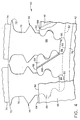
- Figure 1 shows a portion of a gas turbine engine 10 including a combustor 12, a high pressure turbine 14 and a counterrotating low pressure turbine 16 arranged in axial flow relationship along a longitudinal centerline axis 17.
- the high pressure turbine 14 is drivingly connected to a conventional high pressure compressor (not shown) and the low pressure turbine 16 is drivingly connected to a conventional booster and fan (not shown).
- a counterrotating engine is being used as an example to facilitate disclosure of the inventive concept of the present invention, it should be recognized that the present invention is applicable to any sort of gas turbine engine having wheel cavities that require purging.
- the high pressure turbine 14 is a single stage turbine having a stator 18 including a plurality of nozzles 20 (only one shown in Figure 1) and a rotor 22 located aft of the stator 18.
- the rotor 22 includes a rotor disk 24 that rotates about the centerline axis 17, a plurality of turbine blades 26 (only one shown in Figure 1) extending radially outward from the disk 24, a forward retainer 28, and an aft retainer 30.
- the forward retainer 28 is a substantially annular member that is attached to the rotor disk 24 in a known manner so as to prevent the blades 26 from moving in an axially forward direction.
- the aft retainer 30 is an annular member that prevents the blades 26 from moving in an axially aft direction.
- a rotating labyrinth seal 32 is disposed between the forward retainer 28 and the stationary support structure 34 of the high pressure stator 18 to prevent the undesired flow of cooling air bled off from a source such as the engine's high pressure compressor into a wheel cavity 36, which is located between the rotor 22 and the stator 18 and is in fluid communication with the primary gas stream.
- the forward retainer 28 and the rotor disk 24 define a plenum 38 into which cooling air is directed. This cooling air is used for both a subsequently described purpose as well as for cooling the blades 26 in a conventional manner.
- the low pressure turbine 16 is a multi-stage turbine including a first stage that comprises a rotor 40, which is located immediately aft of the high pressure rotor 22 and rotates in the opposite direction thereof.
- the low pressure rotor 40 includes a rotor disk 42 that rotates about the centerline axis 17, a plurality of turbine blades 44 (only one shown in Figure 1) extending radially outward from the disk 42, a forward retainer 46, and an aft retainer 48.
- the forward retainer 46 is an annular member that is attached to the rotor disk 42 in a known manner so as to prevent the blades 44 from moving in an axially forward direction.
- the aft retainer 48 is an annular member that prevents the blades 44 from moving in an axially aft direction.
- a rotating labyrinth seal 50 is disposed between the forward retainer 46 and the oppositely rotating high pressure rotor 22 to prevent the undesired flow of cooling air into a wheel cavity 52, which is located between the high pressure rotor 22 and the first stage low pressure rotor 40 and is in fluid communication with the primary gas stream.
- the forward retainer 46 and rotor disk 42 define a plenum 54 into which the cooling air is directed. This cooling air is used for both a subsequently described purpose as well as for cooling the blades 44 in a conventional manner.
- the low pressure turbine 16 further includes subsequent stages, each having a stator 56 including a plurality of nozzles 58 (only one shown in Figure 1) and a rotor 60 located aft of the stator 56 and drivingly connected to the first stage low pressure rotor 40.
- the low pressure rotor 40 includes a rotor disk 42 having a plurality of turbine blades 44 extending radially outward therefrom.
- the rotor disk 42 has a plurality of circumferentially alternating dovetail slots 62 and posts 64, with each slot 62 defined by adjacent posts 64, disposed about its periphery 66.
- Each disk dovetail slot 62 receives a corresponding dovetail portion 68 of one of the blades 44.
- the disk slots 62 and the dovetail portions 68 are shown to have the so-called fir tree shape although other forms of blade-to-disk interlocking, which are known in the art, may be utilized.
- the blades 44 are axially loaded into the axially extending disk slots 62. Due to the complementary interlocking configurations of the disk slots 62 and the dovetail portions 68, the blades 44 are radially retained in the rotor disk 42.
- each blade 44 includes a shank portion 70 extending radially outward from the dovetail portion 68, a plate-like platform 72 attached to the outer end of the shank portion 70, and an airfoil portion 74 extending radially outward from the platform 72 and into the primary gas stream.
- the blade platforms 72 of adjacent blades 44 abut one another to form a radially inner boundary of the primary gas stream.
- the forward retainer 46 has a radially extending annular flange 76 formed thereon for engaging a radially extending shoulder 78 formed on the forward surface of the rotor disk 40. Engagement of the flange 76 with the shoulder 78 secures the forward retainer 46 relative to the disk 40.
- the outer edge 80 of the forward retainer 46 abuts the forward surface of each blade dovetail portion 68 and disk post 64 so that the blades 44 are prevented from moving in an axially forward direction.
- the rotor disk 40 is provided with a cut back portion 82, aft of the shoulder 78, that intersects the bottoms of the disk slots 62, thereby providing fluid communication between the plenum 54 and each of a plurality of axially extending plenums 84 defined by the bottoms of the disk slots 62 and the radially inner surface 86 of the blade dovetail portions 68.
- Each blade 44 has a substantially radially extending purge slot 88 formed in the forward surface thereof, with the purge slots 88 facing the forward retainer 46.
- each purge slot 88 is formed in the forward surface of the dovetail portion 68 and the shank portion 70 of the corresponding blade 44.
- a first end of each purge slot 88 is located at the radially inner surface 86 of the dovetail portion 68 (or at least at a point radially inward of the outer edge 80 of the forward retainer 46) and is in fluid communication with a corresponding one of the plenums 84.
- each purge slot 88 is located at a point on the forward surface of the shank portion 70 that is radially outward of the outer edge 80 and in fluid communication with the wheel cavity 52 located between the high pressure rotor 22 and the first stage low pressure rotor 40. Accordingly, the purge slots 88 radially traverse the outer edge 80 of the forward retainer 46 and provide fluid communication between the plenums 84 and the wheel cavity 52.
- cooling air is routed to the plenum 54 in a conventional manner from a source that may include but is not limited to the high pressure compressor of the engine 10. From the plenum 54, cooling air flows radially outward into the axially extending plenums 84. As is known in the art, a portion of the cooling air entering each plenum 84 is directed into internal cooling passages (not shown) of the corresponding blade 44 for cooling the blade 44. Another portion of the cooling air flows through the corresponding purge slot 88 into the wheel cavity 52. Because the cooling air is at a higher pressure than the primary gas stream at this point, it flows out of the wheel cavity 52 into the primary gas stream. Thus, the flow of air through the purge slots 88 will combine with any leakage past the labyrinth seal 50 to purge the wheel cavity 52 and prevent hot gas ingestion.
- the total amount of flow through all of the purge slots 88 should be sufficient to adequately purge the wheel cavity 52, but not greater than necessary, since excessive purge flow would be detrimental to overall engine performance.
- the purge slots 88 are sized so as to assure a proper level of purge flow.
- the purge slots 88 will have a depth of approximately 1,27 mm - 2,54 mm (50-100 mils).
- the purge slots 88 are formed as a part of the blade casting so as to avoid additional machining operations.
- each blade 44 it is not necessary for each blade 44 to be provided with a purge slot 88.
- every other blade 44 could be slotted as long as the purge slots 88 were sized to provide sufficient purge flow to the wheel cavity.
- the purge slots 88 were sized to provide sufficient purge flow to the wheel cavity.
- by providing each blade 44 with a purge slot 88 only one blade configuration (i.e., slotted) is required to complete the rotor 40.
- the purge slots 88 are preferably disposed at an angle to a radius drawn from the engine centerline axis 17. By angling the purge slots 88 circumferentially in the direction of rotation of the rotor 40, cooling air exiting the purge slots 88 will be provided with a swirl that reduces the windage heat pickup in the wheel cavity 52 and will be forced back toward the high pressure rotor 22.
- each disk post 64 has a substantially radially extending purge slot 188 formed in the forward surface thereof and facing the forward retainer 46.
- a first end of each purge slot 188 is located at a point radially inward of the outer edge 80 of the - forward retainer 46 and adjacent to the adjoining disk slot 62 so as to be in fluid communication with a corresponding one of the plenums 84.
- the second end of each purge slot 188 is located radially outward of the outer edge 80 (preferably at the disk periphery 66) and in fluid communication with the wheel cavity 52.
- the purge slots 188 radially traverse the outer edge 80 of the forward retainer 46 and provide fluid communication between the plenums 84 and the wheel cavity 52.
- the purge slots 188 are preferably angled circumferentially in the direction of rotor rotation. During engine operation, cooling air from the plenum 54 is directed into the plenums 84, and a portion of this air flows through the purge slots 188 into the wheel cavity 52 where it combines with any leakage past the labyrinth seal 50 to purge the wheel cavity 52 and prevent hot gas ingestion.
- each blade 44 has a substantially radially extending purge slot 288 formed in the aft surface thereof, with the purge slots 288 facing the aft retainer 48.
- each purge slot 288 is formed in the aft surface of the dovetail portion 68 and the shank portion 70 of the corresponding blade 44.
- a first end of each purge slot 288 is located at a point radially inward of the outer edge 81 of the aft retainer 48 and is in fluid communication with a corresponding one of the plenums 84 via an annular gap 90 formed between the aft retainer 48 and the rotor disk 42.
- each purge slot 288 is located at a point on the aft surface of the shank portion 70 that is radially outward of the outer edge 81 and in fluid communication with a wheel cavity 92 located between the first stage low pressure rotor 40 and the low pressure stator 56. Accordingly, the purge slots 288 radially traverse the outer edge 81 of the aft retainer 48 and provide fluid communication between the plenums 84 and the wheel cavity 92. As in the prior embodiments, the purge slots 288 are preferably angled circumferentially in the direction of rotor rotation.
- cooling air from the plenum 54 is directed into the plenums 84, and a portion of this air flows through the gap 90 and the purge slots 288 into the wheel cavity 92 where it combines with any seal leakage to purge the wheel cavity 92 and prevent hot gas ingestion.
- the purge slots 288 could be formed in the aft surfaces of the disk posts 64 instead of the blades 44.
- purge slots are provided in axial surfaces of the blades or the disk posts
- purge slots could alternatively be formed in the outer edge of the forward or aft retainers.
- the present invention has been fully described in connection with the first stage low pressure turbine rotor 40, it should be understood that the present invention is equally applicable to other turbine rotors such as the high pressure rotor 22.
- purge slots would be formed in the forward surfaces of the blades 26 or the disk posts of rotor disk 24 so that cooling air from the plenum 38 could be directed to the wheel cavity 36 located between the high pressure rotor 22 and the high pressure stator 18 in a manner similar to that described above.
- purge slots could be formed in the aft surfaces of the blades 26 or the disk posts of rotor disk 24 so that cooling air from the plenum 38 could be directed past the aft retainer 30 and into the wheel cavity 52 located between the high pressure rotor 22 and the low pressure rotor 40.
Landscapes
- Engineering & Computer Science (AREA)
- Mechanical Engineering (AREA)
- General Engineering & Computer Science (AREA)
- Turbine Rotor Nozzle Sealing (AREA)
Applications Claiming Priority (2)
| Application Number | Priority Date | Filing Date | Title |
|---|---|---|---|
| US09/410,239 US6331097B1 (en) | 1999-09-30 | 1999-09-30 | Method and apparatus for purging turbine wheel cavities |
| US410239 | 1999-09-30 |
Publications (3)
| Publication Number | Publication Date |
|---|---|
| EP1088963A2 EP1088963A2 (en) | 2001-04-04 |
| EP1088963A3 EP1088963A3 (en) | 2003-12-03 |
| EP1088963B1 true EP1088963B1 (en) | 2005-11-30 |
Family
ID=23623864
Family Applications (1)
| Application Number | Title | Priority Date | Filing Date |
|---|---|---|---|
| EP00308540A Expired - Lifetime EP1088963B1 (en) | 1999-09-30 | 2000-09-28 | Method and apparatus for purging turbine wheel cavities |
Country Status (7)
| Country | Link |
|---|---|
| US (1) | US6331097B1 (ja) |
| EP (1) | EP1088963B1 (ja) |
| JP (1) | JP4610710B2 (ja) |
| AT (1) | ATE311524T1 (ja) |
| DE (1) | DE60024385T2 (ja) |
| ES (1) | ES2251350T3 (ja) |
| IL (1) | IL138356A (ja) |
Families Citing this family (42)
| Publication number | Priority date | Publication date | Assignee | Title |
|---|---|---|---|---|
| US6540477B2 (en) * | 2001-05-21 | 2003-04-01 | General Electric Company | Turbine cooling circuit |
| US6749400B2 (en) | 2002-08-29 | 2004-06-15 | General Electric Company | Gas turbine engine disk rim with axially cutback and circumferentially skewed cooling air slots |
| US6910852B2 (en) * | 2003-09-05 | 2005-06-28 | General Electric Company | Methods and apparatus for cooling gas turbine engine rotor assemblies |
| US6981841B2 (en) * | 2003-11-20 | 2006-01-03 | General Electric Company | Triple circuit turbine cooling |
| GB0405679D0 (en) | 2004-03-13 | 2004-04-21 | Rolls Royce Plc | A mounting arrangement for turbine blades |
| US7052240B2 (en) * | 2004-04-15 | 2006-05-30 | General Electric Company | Rotating seal arrangement for turbine bucket cooling circuits |
| US7234918B2 (en) * | 2004-12-16 | 2007-06-26 | Siemens Power Generation, Inc. | Gap control system for turbine engines |
| GB0524929D0 (en) | 2005-12-06 | 2006-01-18 | Rolls Royce Plc | Retention arrangement |
| US7743613B2 (en) * | 2006-11-10 | 2010-06-29 | General Electric Company | Compound turbine cooled engine |
| US7926289B2 (en) * | 2006-11-10 | 2011-04-19 | General Electric Company | Dual interstage cooled engine |
| US7870743B2 (en) * | 2006-11-10 | 2011-01-18 | General Electric Company | Compound nozzle cooled engine |
| US7870742B2 (en) * | 2006-11-10 | 2011-01-18 | General Electric Company | Interstage cooled turbine engine |
| FR2918104B1 (fr) * | 2007-06-27 | 2009-10-09 | Snecma Sa | Dispositif de refroidissement des alveoles d'un disque de rotor de turbomachine a double alimentation en air. |
| FR2925131B1 (fr) * | 2007-12-14 | 2010-01-22 | Snecma | Montage des tubes de pressurisation d'une enceinte interne dans une turbomachine |
| US8096748B2 (en) * | 2008-05-15 | 2012-01-17 | General Electric Company | Apparatus and method for double flow turbine first stage cooling |
| US7993102B2 (en) * | 2009-01-09 | 2011-08-09 | General Electric Company | Rotor cooling circuit |
| US8262356B2 (en) * | 2009-01-30 | 2012-09-11 | General Electric Company | Rotor chamber cover member having aperture for dirt separation and related turbine |
| US8414252B2 (en) * | 2010-01-04 | 2013-04-09 | General Electric Company | Method and apparatus for double flow turbine first stage cooling |
| FR2960260B1 (fr) * | 2010-05-21 | 2014-05-09 | Snecma | Turbomachine comprenant un circuit de ventilation de turbine basse pression ameliore |
| FR2961250B1 (fr) * | 2010-06-14 | 2012-07-20 | Snecma | Dispositif de refroidissement des alveoles d'un disque de rotor de turbomachine a l'aval du cone d'entrainement |
| US8888459B2 (en) * | 2011-08-23 | 2014-11-18 | General Electric Company | Coupled blade platforms and methods of sealing |
| US9091173B2 (en) | 2012-05-31 | 2015-07-28 | United Technologies Corporation | Turbine coolant supply system |
| US9243500B2 (en) | 2012-06-29 | 2016-01-26 | United Technologies Corporation | Turbine blade platform with U-channel cooling holes |
| US9228443B2 (en) * | 2012-10-31 | 2016-01-05 | Solar Turbines Incorporated | Turbine rotor assembly |
| US9347325B2 (en) | 2012-10-31 | 2016-05-24 | Solar Turbines Incorporated | Damper for a turbine rotor assembly |
| US9303519B2 (en) | 2012-10-31 | 2016-04-05 | Solar Turbines Incorporated | Damper for a turbine rotor assembly |
| US9297263B2 (en) * | 2012-10-31 | 2016-03-29 | Solar Turbines Incorporated | Turbine blade for a gas turbine engine |
| JP6125277B2 (ja) * | 2013-02-28 | 2017-05-10 | 三菱重工業株式会社 | ガスタービン |
| FR3006366B1 (fr) * | 2013-05-28 | 2018-03-02 | Safran Aircraft Engines | Roue de turbine dans une turbomachine |
| US9017014B2 (en) * | 2013-06-28 | 2015-04-28 | Siemens Energy, Inc. | Aft outer rim seal arrangement |
| US9528377B2 (en) * | 2013-08-21 | 2016-12-27 | General Electric Company | Method and system for cooling rotor blade angelwings |
| WO2015073112A2 (en) * | 2013-10-03 | 2015-05-21 | United Technologies Corporation | Feature to provide cooling flow to disk |
| US9453427B2 (en) * | 2013-10-30 | 2016-09-27 | General Electric Company | Systems and methods for purging an aft joint of a last stage wheel |
| US10563525B2 (en) * | 2013-12-19 | 2020-02-18 | United Technologies Corporation | Blade feature to support segmented coverplate |
| EP3102793B1 (en) * | 2014-01-24 | 2019-07-10 | United Technologies Corporation | Toggle seal for a rim seal of a rotor assembly |
| FR3018547B1 (fr) * | 2014-03-13 | 2019-07-12 | Safran Aircraft Engines | Systeme d'etancheite entre disques de turbine haute pression avec liaison curvic |
| EP2924237B1 (en) * | 2014-03-25 | 2018-07-11 | Industria de Turbo Propulsores S.A. | Gas turbine rotor |
| US20160146016A1 (en) * | 2014-11-24 | 2016-05-26 | General Electric Company | Rotor rim impingement cooling |
| FR3029960B1 (fr) * | 2014-12-11 | 2021-06-04 | Snecma | Roue a aubes avec joint radial pour une turbine de turbomachine |
| US9835032B2 (en) * | 2015-06-01 | 2017-12-05 | United Technologies Corporation | Disk lug cooling flow trenches |
| US10975714B2 (en) * | 2018-11-22 | 2021-04-13 | Pratt & Whitney Canada Corp. | Rotor assembly with blade sealing tab |
| US11428104B2 (en) * | 2019-07-29 | 2022-08-30 | Pratt & Whitney Canada Corp. | Partition arrangement for gas turbine engine and method |
Family Cites Families (12)
| Publication number | Priority date | Publication date | Assignee | Title |
|---|---|---|---|---|
| NL52254C (ja) * | 1952-01-25 | |||
| US4292008A (en) * | 1977-09-09 | 1981-09-29 | International Harvester Company | Gas turbine cooling systems |
| FR2503247B1 (fr) * | 1981-04-07 | 1985-06-14 | Snecma | Perfectionnements aux etages de turbine a gaz de turboreacteurs munis de moyens de refroidissement par air du disque de la roue de la turbine |
| US4820116A (en) * | 1987-09-18 | 1989-04-11 | United Technologies Corporation | Turbine cooling for gas turbine engine |
| US5281097A (en) * | 1992-11-20 | 1994-01-25 | General Electric Company | Thermal control damper for turbine rotors |
| US5340278A (en) * | 1992-11-24 | 1994-08-23 | United Technologies Corporation | Rotor blade with integral platform and a fillet cooling passage |
| US5388962A (en) | 1993-10-15 | 1995-02-14 | General Electric Company | Turbine rotor disk post cooling system |
| US5503528A (en) * | 1993-12-27 | 1996-04-02 | Solar Turbines Incorporated | Rim seal for turbine wheel |
| US5478207A (en) | 1994-09-19 | 1995-12-26 | General Electric Company | Stable blade vibration damper for gas turbine engine |
| US5630703A (en) | 1995-12-15 | 1997-05-20 | General Electric Company | Rotor disk post cooling system |
| US5800124A (en) * | 1996-04-12 | 1998-09-01 | United Technologies Corporation | Cooled rotor assembly for a turbine engine |
| FR2758855B1 (fr) * | 1997-01-30 | 1999-02-26 | Snecma | Systeme de ventilation des plates-formes des aubes mobiles |
-
1999
- 1999-09-30 US US09/410,239 patent/US6331097B1/en not_active Expired - Fee Related
-
2000
- 2000-09-10 IL IL13835600A patent/IL138356A/en not_active IP Right Cessation
- 2000-09-28 AT AT00308540T patent/ATE311524T1/de not_active IP Right Cessation
- 2000-09-28 DE DE60024385T patent/DE60024385T2/de not_active Expired - Lifetime
- 2000-09-28 EP EP00308540A patent/EP1088963B1/en not_active Expired - Lifetime
- 2000-09-28 ES ES00308540T patent/ES2251350T3/es not_active Expired - Lifetime
- 2000-09-29 JP JP2000297784A patent/JP4610710B2/ja not_active Expired - Fee Related
Also Published As
| Publication number | Publication date |
|---|---|
| ATE311524T1 (de) | 2005-12-15 |
| EP1088963A2 (en) | 2001-04-04 |
| DE60024385T2 (de) | 2006-08-03 |
| JP2001207862A (ja) | 2001-08-03 |
| ES2251350T3 (es) | 2006-05-01 |
| JP4610710B2 (ja) | 2011-01-12 |
| IL138356A (en) | 2004-06-01 |
| US6331097B1 (en) | 2001-12-18 |
| EP1088963A3 (en) | 2003-12-03 |
| IL138356A0 (en) | 2001-10-31 |
| DE60024385D1 (de) | 2006-01-05 |
Similar Documents
| Publication | Publication Date | Title |
|---|---|---|
| EP1088963B1 (en) | Method and apparatus for purging turbine wheel cavities | |
| EP1205636B1 (en) | Turbine blade for a gas turbine and method of cooling said blade | |
| US7238008B2 (en) | Turbine blade retainer seal | |
| US6402471B1 (en) | Turbine blade for gas turbine engine and method of cooling same | |
| EP1211386B1 (en) | Turbine interstage sealing ring and corresponding turbine | |
| EP1531236B1 (en) | Compressor housing with bleed apertures of a gas turbine engine | |
| EP0974733B1 (en) | Turbine nozzle having purge air circuit | |
| US7210900B2 (en) | Gas turbine engine component having bypass circuit | |
| US9976433B2 (en) | Gas turbine engine with non-axisymmetric surface contoured rotor blade platform | |
| US9238970B2 (en) | Blade outer air seal assembly leading edge core configuration | |
| US8152436B2 (en) | Blade under platform pocket cooling | |
| US20070231133A1 (en) | Turbine module for a gas-turbine engine | |
| JP2005155623A (ja) | 三重回路タービン冷却 | |
| CN110325711B (zh) | 涡轮发动机的花键 | |
| US10533425B2 (en) | Doublet vane assembly for a gas turbine engine | |
| US7507072B2 (en) | Turbine module for a gas-turbine engine with rotor that includes a monoblock body | |
| US7223072B2 (en) | Gas turbine engine including airfoils having an improved airfoil film cooling configuration and method therefor | |
| US5205706A (en) | Axial flow turbine assembly and a multi-stage seal | |
| US9677475B2 (en) | Gas turbine engine with high speed and temperature spool cooling system | |
| EP3543468B1 (en) | Turbine tip shroud assembly with plural shroud segments having inter-segment seal arrangement | |
| EP3450697A1 (en) | Vane cluster and corresponding gas turbine engine | |
| GB2570652A (en) | A cooling arrangement for a gas turbine engine aerofoil component platform |
Legal Events
| Date | Code | Title | Description |
|---|---|---|---|
| PUAI | Public reference made under article 153(3) epc to a published international application that has entered the european phase |
Free format text: ORIGINAL CODE: 0009012 |
|
| AK | Designated contracting states |
Kind code of ref document: A2 Designated state(s): AT BE CH CY DE DK ES FI FR GB GR IE IT LI LU MC NL PT SE |
|
| AX | Request for extension of the european patent |
Free format text: AL;LT;LV;MK;RO;SI |
|
| PUAL | Search report despatched |
Free format text: ORIGINAL CODE: 0009013 |
|
| AK | Designated contracting states |
Kind code of ref document: A3 Designated state(s): AT BE CH CY DE DK ES FI FR GB GR IE IT LI LU MC NL PT SE |
|
| AX | Request for extension of the european patent |
Extension state: AL LT LV MK RO SI |
|
| 17P | Request for examination filed |
Effective date: 20040603 |
|
| AKX | Designation fees paid |
Designated state(s): AT BE CH CY DE DK ES FI FR GB GR IE IT LI LU MC NL PT SE |
|
| 17Q | First examination report despatched |
Effective date: 20040908 |
|
| GRAP | Despatch of communication of intention to grant a patent |
Free format text: ORIGINAL CODE: EPIDOSNIGR1 |
|
| GRAS | Grant fee paid |
Free format text: ORIGINAL CODE: EPIDOSNIGR3 |
|
| GRAA | (expected) grant |
Free format text: ORIGINAL CODE: 0009210 |
|
| AK | Designated contracting states |
Kind code of ref document: B1 Designated state(s): AT BE CH CY DE DK ES FI FR GB GR IE IT LI LU MC NL PT SE |
|
| PG25 | Lapsed in a contracting state [announced via postgrant information from national office to epo] |
Ref country code: CH Free format text: LAPSE BECAUSE OF FAILURE TO SUBMIT A TRANSLATION OF THE DESCRIPTION OR TO PAY THE FEE WITHIN THE PRESCRIBED TIME-LIMIT Effective date: 20051130 Ref country code: LI Free format text: LAPSE BECAUSE OF FAILURE TO SUBMIT A TRANSLATION OF THE DESCRIPTION OR TO PAY THE FEE WITHIN THE PRESCRIBED TIME-LIMIT Effective date: 20051130 Ref country code: NL Free format text: LAPSE BECAUSE OF FAILURE TO SUBMIT A TRANSLATION OF THE DESCRIPTION OR TO PAY THE FEE WITHIN THE PRESCRIBED TIME-LIMIT Effective date: 20051130 Ref country code: FI Free format text: LAPSE BECAUSE OF FAILURE TO SUBMIT A TRANSLATION OF THE DESCRIPTION OR TO PAY THE FEE WITHIN THE PRESCRIBED TIME-LIMIT Effective date: 20051130 Ref country code: BE Free format text: LAPSE BECAUSE OF FAILURE TO SUBMIT A TRANSLATION OF THE DESCRIPTION OR TO PAY THE FEE WITHIN THE PRESCRIBED TIME-LIMIT Effective date: 20051130 Ref country code: AT Free format text: LAPSE BECAUSE OF FAILURE TO SUBMIT A TRANSLATION OF THE DESCRIPTION OR TO PAY THE FEE WITHIN THE PRESCRIBED TIME-LIMIT Effective date: 20051130 |
|
| REG | Reference to a national code |
Ref country code: GB Ref legal event code: FG4D Ref country code: CH Ref legal event code: EP |
|
| REG | Reference to a national code |
Ref country code: IE Ref legal event code: FG4D |
|
| REF | Corresponds to: |
Ref document number: 60024385 Country of ref document: DE Date of ref document: 20060105 Kind code of ref document: P |
|
| PG25 | Lapsed in a contracting state [announced via postgrant information from national office to epo] |
Ref country code: DK Free format text: LAPSE BECAUSE OF FAILURE TO SUBMIT A TRANSLATION OF THE DESCRIPTION OR TO PAY THE FEE WITHIN THE PRESCRIBED TIME-LIMIT Effective date: 20060228 Ref country code: GR Free format text: LAPSE BECAUSE OF FAILURE TO SUBMIT A TRANSLATION OF THE DESCRIPTION OR TO PAY THE FEE WITHIN THE PRESCRIBED TIME-LIMIT Effective date: 20060228 |
|
| REG | Reference to a national code |
Ref country code: SE Ref legal event code: TRGR |
|
| REG | Reference to a national code |
Ref country code: ES Ref legal event code: FG2A Ref document number: 2251350 Country of ref document: ES Kind code of ref document: T3 |
|
| PG25 | Lapsed in a contracting state [announced via postgrant information from national office to epo] |
Ref country code: PT Free format text: LAPSE BECAUSE OF FAILURE TO SUBMIT A TRANSLATION OF THE DESCRIPTION OR TO PAY THE FEE WITHIN THE PRESCRIBED TIME-LIMIT Effective date: 20060502 |
|
| NLV1 | Nl: lapsed or annulled due to failure to fulfill the requirements of art. 29p and 29m of the patents act | ||
| REG | Reference to a national code |
Ref country code: CH Ref legal event code: PL |
|
| ET | Fr: translation filed | ||
| PGFP | Annual fee paid to national office [announced via postgrant information from national office to epo] |
Ref country code: ES Payment date: 20060926 Year of fee payment: 7 |
|
| PG25 | Lapsed in a contracting state [announced via postgrant information from national office to epo] |
Ref country code: IE Free format text: LAPSE BECAUSE OF NON-PAYMENT OF DUE FEES Effective date: 20060928 |
|
| PG25 | Lapsed in a contracting state [announced via postgrant information from national office to epo] |
Ref country code: MC Free format text: LAPSE BECAUSE OF NON-PAYMENT OF DUE FEES Effective date: 20060930 |
|
| PLBE | No opposition filed within time limit |
Free format text: ORIGINAL CODE: 0009261 |
|
| STAA | Information on the status of an ep patent application or granted ep patent |
Free format text: STATUS: NO OPPOSITION FILED WITHIN TIME LIMIT |
|
| 26N | No opposition filed |
Effective date: 20060831 |
|
| REG | Reference to a national code |
Ref country code: IE Ref legal event code: MM4A |
|
| PGFP | Annual fee paid to national office [announced via postgrant information from national office to epo] |
Ref country code: SE Payment date: 20060927 Year of fee payment: 7 |
|
| PG25 | Lapsed in a contracting state [announced via postgrant information from national office to epo] |
Ref country code: SE Free format text: LAPSE BECAUSE OF NON-PAYMENT OF DUE FEES Effective date: 20070929 |
|
| EUG | Se: european patent has lapsed | ||
| PG25 | Lapsed in a contracting state [announced via postgrant information from national office to epo] |
Ref country code: LU Free format text: LAPSE BECAUSE OF NON-PAYMENT OF DUE FEES Effective date: 20060928 |
|
| PG25 | Lapsed in a contracting state [announced via postgrant information from national office to epo] |
Ref country code: CY Free format text: LAPSE BECAUSE OF FAILURE TO SUBMIT A TRANSLATION OF THE DESCRIPTION OR TO PAY THE FEE WITHIN THE PRESCRIBED TIME-LIMIT Effective date: 20051130 |
|
| REG | Reference to a national code |
Ref country code: ES Ref legal event code: FD2A Effective date: 20070929 |
|
| PG25 | Lapsed in a contracting state [announced via postgrant information from national office to epo] |
Ref country code: ES Free format text: LAPSE BECAUSE OF NON-PAYMENT OF DUE FEES Effective date: 20070929 |
|
| PGFP | Annual fee paid to national office [announced via postgrant information from national office to epo] |
Ref country code: IT Payment date: 20100925 Year of fee payment: 11 Ref country code: FR Payment date: 20100930 Year of fee payment: 11 |
|
| PGFP | Annual fee paid to national office [announced via postgrant information from national office to epo] |
Ref country code: GB Payment date: 20100927 Year of fee payment: 11 |
|
| PGFP | Annual fee paid to national office [announced via postgrant information from national office to epo] |
Ref country code: DE Payment date: 20100929 Year of fee payment: 11 |
|
| GBPC | Gb: european patent ceased through non-payment of renewal fee |
Effective date: 20110928 |
|
| PG25 | Lapsed in a contracting state [announced via postgrant information from national office to epo] |
Ref country code: IT Free format text: LAPSE BECAUSE OF NON-PAYMENT OF DUE FEES Effective date: 20110928 |
|
| REG | Reference to a national code |
Ref country code: FR Ref legal event code: ST Effective date: 20120531 |
|
| REG | Reference to a national code |
Ref country code: DE Ref legal event code: R119 Ref document number: 60024385 Country of ref document: DE Effective date: 20120403 |
|
| PG25 | Lapsed in a contracting state [announced via postgrant information from national office to epo] |
Ref country code: DE Free format text: LAPSE BECAUSE OF NON-PAYMENT OF DUE FEES Effective date: 20120403 |
|
| PG25 | Lapsed in a contracting state [announced via postgrant information from national office to epo] |
Ref country code: GB Free format text: LAPSE BECAUSE OF NON-PAYMENT OF DUE FEES Effective date: 20110928 Ref country code: FR Free format text: LAPSE BECAUSE OF NON-PAYMENT OF DUE FEES Effective date: 20110930 |