EP1088754A2 - Etrier pour rotor d'hélicoptère en matériaux composites - Google Patents
Etrier pour rotor d'hélicoptère en matériaux composites Download PDFInfo
- Publication number
- EP1088754A2 EP1088754A2 EP00203352A EP00203352A EP1088754A2 EP 1088754 A2 EP1088754 A2 EP 1088754A2 EP 00203352 A EP00203352 A EP 00203352A EP 00203352 A EP00203352 A EP 00203352A EP 1088754 A2 EP1088754 A2 EP 1088754A2
- Authority
- EP
- European Patent Office
- Prior art keywords
- composite
- ply
- edge surface
- innermost
- exposed edge
- Prior art date
- Legal status (The legal status is an assumption and is not a legal conclusion. Google has not performed a legal analysis and makes no representation as to the accuracy of the status listed.)
- Granted
Links
Images

Classifications
-
- B—PERFORMING OPERATIONS; TRANSPORTING
- B64—AIRCRAFT; AVIATION; COSMONAUTICS
- B64C—AEROPLANES; HELICOPTERS
- B64C27/00—Rotorcraft; Rotors peculiar thereto
- B64C27/32—Rotors
- B64C27/46—Blades
-
- B—PERFORMING OPERATIONS; TRANSPORTING
- B64—AIRCRAFT; AVIATION; COSMONAUTICS
- B64C—AEROPLANES; HELICOPTERS
- B64C27/00—Rotorcraft; Rotors peculiar thereto
- B64C27/32—Rotors
- B64C27/33—Rotors having flexing arms
-
- Y—GENERAL TAGGING OF NEW TECHNOLOGICAL DEVELOPMENTS; GENERAL TAGGING OF CROSS-SECTIONAL TECHNOLOGIES SPANNING OVER SEVERAL SECTIONS OF THE IPC; TECHNICAL SUBJECTS COVERED BY FORMER USPC CROSS-REFERENCE ART COLLECTIONS [XRACs] AND DIGESTS
- Y10—TECHNICAL SUBJECTS COVERED BY FORMER USPC
- Y10T—TECHNICAL SUBJECTS COVERED BY FORMER US CLASSIFICATION
- Y10T29/00—Metal working
- Y10T29/49—Method of mechanical manufacture
- Y10T29/49316—Impeller making
- Y10T29/49318—Repairing or disassembling
-
- Y—GENERAL TAGGING OF NEW TECHNOLOGICAL DEVELOPMENTS; GENERAL TAGGING OF CROSS-SECTIONAL TECHNOLOGIES SPANNING OVER SEVERAL SECTIONS OF THE IPC; TECHNICAL SUBJECTS COVERED BY FORMER USPC CROSS-REFERENCE ART COLLECTIONS [XRACs] AND DIGESTS
- Y10—TECHNICAL SUBJECTS COVERED BY FORMER USPC
- Y10T—TECHNICAL SUBJECTS COVERED BY FORMER US CLASSIFICATION
- Y10T29/00—Metal working
- Y10T29/49—Method of mechanical manufacture
- Y10T29/49316—Impeller making
- Y10T29/49336—Blade making
- Y10T29/49337—Composite blade
-
- Y—GENERAL TAGGING OF NEW TECHNOLOGICAL DEVELOPMENTS; GENERAL TAGGING OF CROSS-SECTIONAL TECHNOLOGIES SPANNING OVER SEVERAL SECTIONS OF THE IPC; TECHNICAL SUBJECTS COVERED BY FORMER USPC CROSS-REFERENCE ART COLLECTIONS [XRACs] AND DIGESTS
- Y10—TECHNICAL SUBJECTS COVERED BY FORMER USPC
- Y10T—TECHNICAL SUBJECTS COVERED BY FORMER US CLASSIFICATION
- Y10T428/00—Stock material or miscellaneous articles
- Y10T428/24—Structurally defined web or sheet [e.g., overall dimension, etc.]
- Y10T428/24777—Edge feature
- Y10T428/24785—Edge feature including layer embodying mechanically interengaged strands, strand portions or strand-like strips [e.g., weave, knit, etc.]
Definitions
- the present invention relates generally to the prevention of mid-plane delamination failures in laminated composite flexures.
- the present invention relates to a method and apparatus for increasing the strength and fatigue life of helicopter main rotor yokes constructed of laminated composite materials.
- Helicopter main rotor yokes combine to form main rotor hubs and provide means to connect the main rotor blades to the main rotor mast, which provides the necessary drive torque.
- These main rotor yokes are typically elongated members having center sections adapted for connection to the rotor mast, and outwardly extending arm sections.
- the main rotor blades of helicopters exert high centrifugal forces on the rotor yokes of the main rotor hub.
- the main rotor yokes are subjected to a variety of other static and dynamic forces and motions, including feathering, flapping, and lead-lag forces and motions.
- feathering forces and motions are torsional pitch forces and motions generated by the variable pitch of the rotor blades; flapping forces and motions are bending forces and motions generated by the rotor blades out of the plane of rotation of the rotor blades; and lead-lag forces and motions are bending forces and motions generated by the rotor blades in the plane of rotation of the rotor blades.
- rotor yokes are subjected to such a large variety of tension and bending forces and motions, they must be both strong and flexible. Often this can only be achieved by the addition of moving parts and linkages. As such, conventional main rotor yokes and rotor hubs have to include complicated systems of bearings and supports to accommodate these forces. These are usually complex systems requiring a great deal of maintenance and service in the form of lubrication and inspection. This leads to high costs in the form of increased labor, increased materials, reduced operating time, and reduced service life. However, in recent years, these conventional rotor yokes, which require complex bearing and lubrication systems, have given way to "bearingless" rotor yokes made from composite materials, which do not require any bearings or lubrication systems.
- Composite bearingless rotor yokes are specifically designed to compensate for the centrifugal, feathering, flapping, lead-lag, and other static and dynamic forces and motions exerted upon the rotor yokes by the rotor blades. Because these bearingless rotor yokes are composite materials, they provide all of the benefits generally associated with composite flexures: high strength-to-weight ratios, reduced weight, and reduced maintenance; without the need for costly linkages, bearings and lubrication systems. The lengths, thicknesses, and cross-sectional profiles of these composite rotor yokes can be varied to produce very specific mechanical strengths and properties. However, once the appropriate configuration and dimensions of such a rotor yoke have been determined for a particular application, there is little or no room for additional structural enhancements.
- laminated composite flexures are susceptible to failure in the form of mid-plane delamination.
- Mid-plane delamination initiates at the exposed edges of the laminate due to edge effect concentrations and progresses inward toward the center.
- inter-laminar shear stresses are concentrated at the edges of laminated composite flexures.
- Bearingless composite rotor yokes are no exception to these rules. The cyclic bending loads and motions, both in-plane and out-of-plane, exerted upon composite rotor yokes can lead to mid-plane delamination fatigue failure.
- an edge member having an innermost, an outermost, and internal layers or plies.
- the internal plies of the edge member conform to an exposed edge surface of the composite flexure. These internal plies have a height approximately equal to the height of the edge surface of the composite flexure.
- the innermost and outermost plies of the edge member also conform to the edge surface of the composite flexure. However, the innermost and outermost are larger than the internal plies so that the innermost and outermost plies can be overlapped onto and attached to the uppermost and lowermost plies of the composite flexure.
- the edge member of the present invention provides significant advantages. Because inter-laminar shear stresses generated within the composite flexure peak at or near the edge of the composite flexure, the edge member of the present invention can be configured to isolate the peak shear stresses. Because only the innermost and outermost plies of the edge member of the present invention are overlapped onto the composite flexure, the thickness of the composite flexure is not significantly increased. The edge member of the present invention protects the composite flexure form random impact damage, as from handling. Because the edge member of the present invention places a watertight seal on the exposed edges of the composite flexure, moisture uptake by the composite flexure in high humidity environments is greatly reduced.
- FIG. 1 the preferred embodiment of the protective edge member for composite flexures of the present invention is illustrated.
- a composite flexure for which the edge member of the present invention is particularly suited is a helicopter main rotor yoke 11.
- Yoke 11 is an elongated member having a center section 13 and two integral arm sections 15 and 17 that extend outwardly in opposite directions from center section 13.
- Yoke 11 will be described herein with reference to three orthogonal axes x, y, and z.
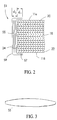
- Yoke 11 is of conventional laminar construction, preferably being made of a plurality of layers 18 (see Figure 2) of composite materials, such as fiberglass.
- the composite materials that form yoke 11 are layered one upon another, generally in the x-y plane, and then cured in a conventional manner.
- An uppermost layer 20 (see Figure 2) of yoke 11 would form an upper surface 11a
- a lowermost layer 22 (see Figure 2) of yoke 11 would form an opposing lower surface 11b (see Figure 2).
- yoke 11 is trimmed to size.
- Other post-cure finishing and machining may be necessary.
- a composite flexure would be left with laminated edge surfaces generally parallel to the z axis that are exposed, such as exposed edge surface 24 of yoke 11 in Figure 2). Such exposed edge surfaces are susceptible to various problems.
- the main problem is that mid-plane delamination initiates on the exposed edge surface due to edge effect concentrations and progresses toward the center of the composite flexure as the composite flexure is cyclically loaded.
- Another problem is that the exposed edge surfaces are susceptible to random impact damage, such as from handling.
- Another problem is that composite flexures with exposed edge surfaces uptake moisture in high humidity environments.
- the protective edge members of the present invention overcome these problems.
- Center section 13 of yoke 11 preferably curves outward in the ⁇ x directions and is thicker in the ⁇ z directions, thereby providing added volume and strength in center section 13.
- a mast aperture 19 is located at the center of center section 13.
- Mast aperture 19 receives a conventional drive mast (not shown) of a conventional helicopter transmission (not shown).
- the drive mast is typically adapted to be coupled to yoke 11 by conventional fastening means, such as bolts (not shown), that pass through a plurality of bolt apertures 21 that are arranged around mast aperture 19.
- Bolt apertures 21 also provide a means for an additional rotor yoke (not shown but identical to yoke 11) to be coupled to yoke 11.
- Such coupling of yokes 11 forms a main rotor hub (not shown).
- Flapping flexure regions 23a and 23b experience a significant amount of out-of-plane bending, or flapping, forces and motions. Flapping flexure regions 23a and 23b transition into arm sections 15 and 17.
- An aperture 25a passes through yoke 11 along the z axis at a point where flapping flexure region 23a transitions into arm section 15.
- an aperture 25b passes through yoke 11 along the z axis at a point where flapping flexure region 23b transitions into arm section 17.
- apertures 25a and 25b receive a conventional elastomeric shear restraint bearing (not shown). It should be understood that apertures 25a and 25b may vary in size, shape, arrangement, number, and location dependent upon the particular shear restraint bearing system employed. Such variations would have no appreciable effect on the functionality of the present invention.
- arm sections 15 and 17 extend outward in opposite directions along axis y from flapping flexure regions 23a and 23b, respectively.
- Arm section 15 includes a plurality of flanges and curvatures 15a.
- arm section 17 includes a plurality of flanges and curvatures 17a.
- the shape and dimensions of flanges and curvatures 15a and 17a are predetermined to allow arm sections 15 and 17 to twist in torsion to accommodate the feathering, or pitch, motions generated by variable pitch rotor blades (not shown).
- Arm section 15 terminates with an end portion 27 having apertures 29 configured to receive a sleeve member (not shown) that covers the connection of a first rotor blade (not shown) to yoke 11.
- arm section 17 terminates with an end portion 31 having apertures 33 configured to receive a sleeve member (not shown) that covers the connection of a second rotor blade (not shown) to yoke 11.
- yoke 11 The length, thicknesses, and cross-sectional profiles of yoke 11 are chosen such that yoke 11 possesses certain selected mechanical properties in selected sections of yoke 11. As such, yoke 11 is capable of withstanding the centrifugal, feathering, flapping, lead-lag, and other static and dynamic forces and motions generated by the rotor blades.
- feathering forces and motions are torsional pitch forces and motions generated by the variable pitch of the rotor blades; flapping forces and motions are bending forces and motions generated by the rotor blades out of the plane of rotation of the rotor blades; and lead-lag forces and motions are bending forces and motions generated by the rotor blades in the plane of rotation of the rotor blades.
- yoke 11 is a bearingless helicopter main rotor yoke of the type described above. Because yoke 11 does not have any bearings or other moving parts, there is no need for lubrication. This leads to significant savings in terms of weight, labor, and maintenance.
- Edge surface 24 of laminated composite layers 18, 20, and 22 is exposed at least in the range of center section 13 and flapping flexure regions 23a and 23b. Because flapping flexure regions 23a and 23b are subjected to a significant amount of cyclical bending, or flapping, forces and motions, yoke 11 is particularly susceptible to mid-plane delamination failure at flapping flexure regions 23a and 23b. To prevent such mid-plane delamination failure in flapping flexure regions 23a and 23b, a plurality of elongated edge members 51 and 53 are attached to yoke 11 at flapping flexure regions 23a and 23b after curing and post-cure finishing of yoke 11. To provide additional strength, it is preferred that edge members 51 and 53 extend continuously through center section 13 from one flapping flexure region 23a to the other flapping flexure region 23b, as is shown in Figure 1.
- Each edge member 51 and 53 includes at least one interior layer or ply 55, at least one innermost layer or ply 57, and at least one outermost layer or ply 59.
- Interior plies 55, innermost ply 57, and outermost ply 59 are preferably made of a composite material, such as fiberglass. It is preferred that all of interior plies 55 be disposed between innermost ply 57 and outermost ply 59.
- each interior ply 55 be long enough to extend over the combined length of center section 13 and both flapping flexure regions 23a and 23b (see Figure 1). It is further preferred that the width of each interior ply 55 vary along the length such that the width of each interior ply 55 is equal to, and corresponding to, the thickness in the z direction of center section 13 and flapping flexure regions 23a and 23b. Thus, in plan view, each interior ply 55 looks generally like ply 55 in Figure 3.
- Each edge member 51 and 53 is prepared by first applying and attaching innermost ply 57 to edge surface 24 so as to cover edge surface 24.
- Innermost ply 57 is overlapped onto upper surface 11a and lower surface 11b of yoke 11 by a distance d 1 .
- Distance d 1 is preferably about one inch, but may vary depending upon the composite flexure to which edge member 51 or 53 is applied.
- Innermost ply 57 is generally of the same shape as interior plies 55; however, because edge surface 24 is curved in the x-y plane and varies in thickness along the z axis, some darting, or removal of small triangular pieces, may be necessary to achieve a smooth, conforming fit between innermost ply 57 and yoke 11.
- a plurality of interior plies 55 preferably four, are successively applied and attached to innermost ply 57.
- outermost ply 59 is applied.
- Outermost ply 59 is generally shaped the same as innermost ply 57; however, outermost ply 59 is somewhat larger to allow coverage of the plurality of interior plies 55.
- Outermost ply 59 is also overlapped onto upper surface 11a and lower surface 11b of yoke 11 by distance d 1 .
- Outermost ply 59 is applied and attached to innermost ply 57 at the portion of innermost ply 57 that extends distance d 1 onto upper surface 11a and lower surface 11b of yoke 11.
- edge members 51 and 53 be applied to yoke 11 at room temperature and allowed to cure at room temperature.
- edge member 51 and 53 adds a distance d 2 to the width in the x direction of yoke 11. Because inter-laminar shear stresses peak at the exposed edge surfaces 24 of yoke 11, edge members 51 and 53 allow the peak shear stresses to be isolated within edge members 51 and 53. This reduces the effects of edge effect concentrations, thereby significantly reducing or eliminating the probability of failure from mid-plane delamination. In addition, edge members 51 and 53 allow yoke 11 to withstand greater motions for longer periods of time. For example, yoke 11 having edge members 51 and 53 has an endurance limit flapping angle capability that is 25% more than a similar yoke without edge members 51 and 53.
- Edge members 51 and 53 completely cover and surround exposed edge surface 24, providing a watertight seal. Therefore, edge members 51 and 53 protect yoke 11 from random impact damage, such as from handling. In addition, because edge members 51 and 53 form a watertight seal around exposed edge 24 at central section 13 and flapping flexure regions 23a and 23b, yoke 11 is protected from inter-laminar moisture uptake in yoke 11 in high humidity environments is reduced.
Applications Claiming Priority (2)
| Application Number | Priority Date | Filing Date | Title |
|---|---|---|---|
| US407691 | 1999-09-28 | ||
| US09/407,691 US6375426B1 (en) | 1999-09-28 | 1999-09-28 | Protective edge members for composite flexures |
Publications (3)
| Publication Number | Publication Date |
|---|---|
| EP1088754A2 true EP1088754A2 (fr) | 2001-04-04 |
| EP1088754A3 EP1088754A3 (fr) | 2002-04-03 |
| EP1088754B1 EP1088754B1 (fr) | 2003-03-26 |
Family
ID=23613135
Family Applications (1)
| Application Number | Title | Priority Date | Filing Date |
|---|---|---|---|
| EP00203352A Expired - Lifetime EP1088754B1 (fr) | 1999-09-28 | 2000-09-27 | Etrier pour rotor d'hélicoptère en matériaux composites |
Country Status (6)
| Country | Link |
|---|---|
| US (1) | US6375426B1 (fr) |
| EP (1) | EP1088754B1 (fr) |
| JP (1) | JP2001122195A (fr) |
| KR (1) | KR100726201B1 (fr) |
| CA (1) | CA2320606C (fr) |
| DE (2) | DE1088754T1 (fr) |
Cited By (5)
| Publication number | Priority date | Publication date | Assignee | Title |
|---|---|---|---|---|
| EP1251068A3 (fr) * | 2001-04-20 | 2004-02-04 | Bell Helicopter Textron Inc. | Poutre de flexion composite |
| FR2893914A1 (fr) * | 2005-11-29 | 2007-06-01 | Eurocopter France | Protection antichoc d'une piece mecanique. |
| CN102795338A (zh) * | 2012-07-27 | 2012-11-28 | 北京卫星制造厂 | 一种微小型无人机碳纤维旋翼及其制备方法 |
| EP3038909A1 (fr) * | 2013-08-28 | 2016-07-06 | Sikorsky Aircraft Corporation | Moyeu de rotor pour aéronef à voilure tournante |
| CN112550669A (zh) * | 2020-12-11 | 2021-03-26 | 中国直升机设计研究所 | 一种跷跷板式无轴承尾桨毂及直升机尾桨 |
Families Citing this family (10)
| Publication number | Priority date | Publication date | Assignee | Title |
|---|---|---|---|---|
| US6581365B1 (en) * | 2001-12-07 | 2003-06-24 | Harris Corporation | Controlling thermally induced beam twist |
| DE10348981B4 (de) * | 2003-10-22 | 2009-04-09 | Eurocopter Deutschland Gmbh | Rotor, insbesondere für ein Drehflugzeug |
| KR100600595B1 (ko) * | 2005-06-01 | 2006-07-13 | 동아전기부품 주식회사 | 프리히터용 방열부 |
| US8573528B2 (en) * | 2008-04-21 | 2013-11-05 | Boris Andreevich Polovinkin | Vertical take-off and vertical landing gyroplane |
| US10059438B2 (en) * | 2011-12-26 | 2018-08-28 | Textron Innovations Inc. | Hub assembly with grease lubricated roller bearing and tension-torsion strap |
| EP2772430B1 (fr) * | 2013-02-27 | 2016-06-29 | AIRBUS HELICOPTERS DEUTSCHLAND GmbH | Bras de flexion cruciforme d'une partie et procédé de fabrication d'un tel bras |
| EP2783981B1 (fr) | 2013-03-28 | 2017-03-15 | AIRBUS HELICOPTERS DEUTSCHLAND GmbH | Barre de matériau matriciel composite |
| US9499262B2 (en) | 2013-08-02 | 2016-11-22 | Bell Helicopter Textron Inc. | Composite flexure for tiltrotor rotor system |
| EP2883790B1 (fr) | 2013-12-10 | 2017-11-22 | AIRBUS HELICOPTERS DEUTSCHLAND GmbH | Poutre pour un rotor de giravion et ledit rotor |
| EP2899121B1 (fr) | 2014-01-22 | 2016-11-16 | AIRBUS HELICOPTERS DEUTSCHLAND GmbH | Unité de flexion pour rotor à pales multiples sans palier ou sans palier et charnière et aéronef à voilure tournante |
Family Cites Families (12)
| Publication number | Priority date | Publication date | Assignee | Title |
|---|---|---|---|---|
| US4189283A (en) | 1978-07-12 | 1980-02-19 | The United States Of America As Represented By The Secretary Of The Navy | Rotor hub for a helicopter |
| US4293276A (en) * | 1978-10-27 | 1981-10-06 | Textron Inc. | Laminated composite rotor yoke |
| US4466774A (en) | 1982-08-30 | 1984-08-21 | United Technologies Corporation | Composite flexbeam joint |
| US4966802A (en) | 1985-05-10 | 1990-10-30 | The Boeing Company | Composites made of fiber reinforced resin elements joined by adhesive |
| US4746272A (en) * | 1986-07-23 | 1988-05-24 | United Technologies Corporation | Lobed composite flexbeam |
| US4898515A (en) | 1986-07-23 | 1990-02-06 | United Technologies Corporation | External wrap of composite flexbeam |
| US4818179A (en) | 1987-07-30 | 1989-04-04 | United Technologies Corporation | Composite helicopter rotor hub |
| CA2069125A1 (fr) | 1991-07-01 | 1993-01-02 | Gary J. Jacaruso | Outil de faconnage composite |
| TW244340B (fr) | 1992-07-21 | 1995-04-01 | Akzo Nv | |
| US5431538A (en) | 1993-07-01 | 1995-07-11 | United Technologies Corporation | Hybrid composite flexbeam for a helicopter bearingless main rotor assembly |
| US5690474A (en) * | 1996-07-18 | 1997-11-25 | Sikorsky Aircraft Corporation | Optimized composite flexbeam for helicopter tail rotors |
| US5820344A (en) * | 1997-06-27 | 1998-10-13 | Mcdonnell Douglas Corporation | Contoured flexure strap for helicopter rotor system |
-
1999
- 1999-09-28 US US09/407,691 patent/US6375426B1/en not_active Expired - Lifetime
-
2000
- 2000-09-26 CA CA002320606A patent/CA2320606C/fr not_active Expired - Lifetime
- 2000-09-27 EP EP00203352A patent/EP1088754B1/fr not_active Expired - Lifetime
- 2000-09-27 JP JP2000293303A patent/JP2001122195A/ja active Pending
- 2000-09-27 DE DE1088754T patent/DE1088754T1/de active Pending
- 2000-09-27 KR KR1020000056687A patent/KR100726201B1/ko active IP Right Grant
- 2000-09-27 DE DE60001784T patent/DE60001784T2/de not_active Expired - Lifetime
Non-Patent Citations (1)
| Title |
|---|
| None |
Cited By (9)
| Publication number | Priority date | Publication date | Assignee | Title |
|---|---|---|---|---|
| EP1251068A3 (fr) * | 2001-04-20 | 2004-02-04 | Bell Helicopter Textron Inc. | Poutre de flexion composite |
| FR2893914A1 (fr) * | 2005-11-29 | 2007-06-01 | Eurocopter France | Protection antichoc d'une piece mecanique. |
| US7618238B2 (en) | 2005-11-29 | 2009-11-17 | Eurocopter | Anti-impact shield for a mechanical part |
| CN102795338A (zh) * | 2012-07-27 | 2012-11-28 | 北京卫星制造厂 | 一种微小型无人机碳纤维旋翼及其制备方法 |
| CN102795338B (zh) * | 2012-07-27 | 2014-10-08 | 北京卫星制造厂 | 一种微小型无人机碳纤维旋翼的制备方法 |
| EP3038909A1 (fr) * | 2013-08-28 | 2016-07-06 | Sikorsky Aircraft Corporation | Moyeu de rotor pour aéronef à voilure tournante |
| EP3038909A4 (fr) * | 2013-08-28 | 2017-05-10 | Sikorsky Aircraft Corporation | Moyeu de rotor pour aéronef à voilure tournante |
| US10301012B2 (en) | 2013-08-28 | 2019-05-28 | Sikorsky Aircraft Corporation | Rotor hub for rotary wing aircraft |
| CN112550669A (zh) * | 2020-12-11 | 2021-03-26 | 中国直升机设计研究所 | 一种跷跷板式无轴承尾桨毂及直升机尾桨 |
Also Published As
| Publication number | Publication date |
|---|---|
| US6375426B1 (en) | 2002-04-23 |
| DE1088754T1 (de) | 2001-10-11 |
| EP1088754A3 (fr) | 2002-04-03 |
| KR100726201B1 (ko) | 2007-06-11 |
| CA2320606A1 (fr) | 2001-03-28 |
| JP2001122195A (ja) | 2001-05-08 |
| DE60001784T2 (de) | 2003-12-04 |
| EP1088754B1 (fr) | 2003-03-26 |
| KR20010050665A (ko) | 2001-06-15 |
| DE60001784D1 (de) | 2003-04-30 |
| CA2320606C (fr) | 2009-02-24 |
Similar Documents
| Publication | Publication Date | Title |
|---|---|---|
| EP1088754B1 (fr) | Etrier pour rotor d'hélicoptère en matériaux composites | |
| JP2547289B2 (ja) | ヘリコプター用ローター装置のピッチハウジング構造体 | |
| KR100468508B1 (ko) | 헬리콥터 주회전 날개용 복합 팁 캡 조립체 | |
| US4971641A (en) | Method of making counterrotating aircraft propeller blades | |
| US20090155086A1 (en) | Rotorcraft blade, a rotorcraft rotor provided with said blade, and a method of fabricating said blade | |
| AU655504B2 (en) | Bearingless main rotor assembly torque tube | |
| EP0448705B1 (fr) | Pale de rotor | |
| US9308992B2 (en) | Helicopter blade retention composite yoke | |
| US5645400A (en) | Composite cuff structure for helicopter rotors | |
| US6918839B2 (en) | Damage tolerant shaft | |
| EP1251068B1 (fr) | Poutre de flexion composite | |
| US5462409A (en) | Leading edge weight retention assembly for a helicopter rotor | |
| EP0785889B1 (fr) | Ensemble de montage a palier amortisseur pour rotors sans paliers | |
| GB2224784A (en) | Propeller blades | |
| US20170291701A1 (en) | Fiber Orientation to Allow for Automated Ply Placement With Composite Rotor Yokes | |
| CA1095664A (fr) | Profil aerodynamique composite |
Legal Events
| Date | Code | Title | Description |
|---|---|---|---|
| PUAI | Public reference made under article 153(3) epc to a published international application that has entered the european phase |
Free format text: ORIGINAL CODE: 0009012 |
|
| AK | Designated contracting states |
Kind code of ref document: A2 Designated state(s): AT BE CH CY DE DK ES FI FR GB GR IE IT LI LU MC NL PT SE Kind code of ref document: A2 Designated state(s): DE FR GB IT |
|
| AX | Request for extension of the european patent |
Free format text: AL;LT;LV;MK;RO;SI |
|
| EL | Fr: translation of claims filed | ||
| DET | De: translation of patent claims | ||
| PUAL | Search report despatched |
Free format text: ORIGINAL CODE: 0009013 |
|
| AK | Designated contracting states |
Kind code of ref document: A3 Designated state(s): AT BE CH CY DE DK ES FI FR GB GR IE IT LI LU MC NL PT SE |
|
| AX | Request for extension of the european patent |
Free format text: AL;LT;LV;MK;RO;SI |
|
| 17P | Request for examination filed |
Effective date: 20020323 |
|
| GRAG | Despatch of communication of intention to grant |
Free format text: ORIGINAL CODE: EPIDOS AGRA |
|
| GRAG | Despatch of communication of intention to grant |
Free format text: ORIGINAL CODE: EPIDOS AGRA |
|
| 17Q | First examination report despatched |
Effective date: 20020617 |
|
| GRAG | Despatch of communication of intention to grant |
Free format text: ORIGINAL CODE: EPIDOS AGRA |
|
| GRAH | Despatch of communication of intention to grant a patent |
Free format text: ORIGINAL CODE: EPIDOS IGRA |
|
| GRAH | Despatch of communication of intention to grant a patent |
Free format text: ORIGINAL CODE: EPIDOS IGRA |
|
| AKX | Designation fees paid |
Free format text: DE FR GB IT |
|
| GRAA | (expected) grant |
Free format text: ORIGINAL CODE: 0009210 |
|
| AK | Designated contracting states |
Designated state(s): DE FR GB IT |
|
| REG | Reference to a national code |
Ref country code: GB Ref legal event code: FG4D |
|
| REF | Corresponds to: |
Ref document number: 60001784 Country of ref document: DE Date of ref document: 20030430 Kind code of ref document: P |
|
| REG | Reference to a national code |
Ref country code: IE Ref legal event code: FG4D |
|
| ET | Fr: translation filed | ||
| PLBE | No opposition filed within time limit |
Free format text: ORIGINAL CODE: 0009261 |
|
| STAA | Information on the status of an ep patent application or granted ep patent |
Free format text: STATUS: NO OPPOSITION FILED WITHIN TIME LIMIT |
|
| 26N | No opposition filed |
Effective date: 20031230 |
|
| REG | Reference to a national code |
Ref country code: IE Ref legal event code: MM4A |
|
| REG | Reference to a national code |
Ref country code: FR Ref legal event code: PLFP Year of fee payment: 17 |
|
| REG | Reference to a national code |
Ref country code: FR Ref legal event code: PLFP Year of fee payment: 18 |
|
| REG | Reference to a national code |
Ref country code: FR Ref legal event code: PLFP Year of fee payment: 19 |
|
| PGFP | Annual fee paid to national office [announced via postgrant information from national office to epo] |
Ref country code: IT Payment date: 20190920 Year of fee payment: 20 Ref country code: FR Payment date: 20190925 Year of fee payment: 20 |
|
| PGFP | Annual fee paid to national office [announced via postgrant information from national office to epo] |
Ref country code: GB Payment date: 20190927 Year of fee payment: 20 |
|
| PGFP | Annual fee paid to national office [announced via postgrant information from national office to epo] |
Ref country code: DE Payment date: 20190927 Year of fee payment: 20 |
|
| REG | Reference to a national code |
Ref country code: DE Ref legal event code: R071 Ref document number: 60001784 Country of ref document: DE |
|
| REG | Reference to a national code |
Ref country code: GB Ref legal event code: PE20 Expiry date: 20200926 |
|
| PG25 | Lapsed in a contracting state [announced via postgrant information from national office to epo] |
Ref country code: GB Free format text: LAPSE BECAUSE OF EXPIRATION OF PROTECTION Effective date: 20200926 |