EP1088676A1 - Liquid pressure transfer method for loop-like workpiece and product decorated thereby - Google Patents
Liquid pressure transfer method for loop-like workpiece and product decorated thereby Download PDFInfo
- Publication number
- EP1088676A1 EP1088676A1 EP00301593A EP00301593A EP1088676A1 EP 1088676 A1 EP1088676 A1 EP 1088676A1 EP 00301593 A EP00301593 A EP 00301593A EP 00301593 A EP00301593 A EP 00301593A EP 1088676 A1 EP1088676 A1 EP 1088676A1
- Authority
- EP
- European Patent Office
- Prior art keywords
- transfer
- workpiece
- pattern
- rod
- film
- Prior art date
- Legal status (The legal status is an assumption and is not a legal conclusion. Google has not performed a legal analysis and makes no representation as to the accuracy of the status listed.)
- Granted
Links
- 238000012546 transfer Methods 0.000 title claims abstract description 315
- 239000007788 liquid Substances 0.000 title claims abstract description 94
- 238000000034 method Methods 0.000 title claims abstract description 25
- 238000013459 approach Methods 0.000 claims abstract description 17
- 238000005034 decoration Methods 0.000 claims abstract description 14
- 238000010023 transfer printing Methods 0.000 claims description 25
- 239000012190 activator Substances 0.000 claims description 14
- 238000007654 immersion Methods 0.000 description 19
- 239000000463 material Substances 0.000 description 12
- 230000002093 peripheral effect Effects 0.000 description 11
- 239000011248 coating agent Substances 0.000 description 5
- 238000000576 coating method Methods 0.000 description 5
- 238000006243 chemical reaction Methods 0.000 description 4
- 238000007639 printing Methods 0.000 description 4
- 238000012545 processing Methods 0.000 description 4
- 239000002904 solvent Substances 0.000 description 4
- 238000007667 floating Methods 0.000 description 3
- 238000009877 rendering Methods 0.000 description 3
- 238000003860 storage Methods 0.000 description 3
- 230000015572 biosynthetic process Effects 0.000 description 2
- 230000003247 decreasing effect Effects 0.000 description 2
- 238000011161 development Methods 0.000 description 2
- 238000001035 drying Methods 0.000 description 2
- 239000010985 leather Substances 0.000 description 2
- 238000004519 manufacturing process Methods 0.000 description 2
- 239000005445 natural material Substances 0.000 description 2
- 239000004033 plastic Substances 0.000 description 2
- OKTJSMMVPCPJKN-UHFFFAOYSA-N Carbon Chemical compound [C] OKTJSMMVPCPJKN-UHFFFAOYSA-N 0.000 description 1
- 239000013543 active substance Substances 0.000 description 1
- 230000002411 adverse Effects 0.000 description 1
- 229910052799 carbon Inorganic materials 0.000 description 1
- 238000010276 construction Methods 0.000 description 1
- 230000000694 effects Effects 0.000 description 1
- 239000000835 fiber Substances 0.000 description 1
- 238000010438 heat treatment Methods 0.000 description 1
- 238000005304 joining Methods 0.000 description 1
- 230000000873 masking effect Effects 0.000 description 1
- 239000007769 metal material Substances 0.000 description 1
- 238000012986 modification Methods 0.000 description 1
- 230000004048 modification Effects 0.000 description 1
- 239000000049 pigment Substances 0.000 description 1
- 239000004014 plasticizer Substances 0.000 description 1
- 238000005498 polishing Methods 0.000 description 1
- 239000011347 resin Substances 0.000 description 1
- 229920005989 resin Polymers 0.000 description 1
- 238000009751 slip forming Methods 0.000 description 1
- 238000005507 spraying Methods 0.000 description 1
- 239000004575 stone Substances 0.000 description 1
- 238000011144 upstream manufacturing Methods 0.000 description 1
- 238000005406 washing Methods 0.000 description 1
- XLYOFNOQVPJJNP-UHFFFAOYSA-N water Substances O XLYOFNOQVPJJNP-UHFFFAOYSA-N 0.000 description 1
- 238000004804 winding Methods 0.000 description 1
Images




Classifications
-
- B—PERFORMING OPERATIONS; TRANSPORTING
- B41—PRINTING; LINING MACHINES; TYPEWRITERS; STAMPS
- B41M—PRINTING, DUPLICATING, MARKING, OR COPYING PROCESSES; COLOUR PRINTING
- B41M5/00—Duplicating or marking methods; Sheet materials for use therein
-
- B—PERFORMING OPERATIONS; TRANSPORTING
- B41—PRINTING; LINING MACHINES; TYPEWRITERS; STAMPS
- B41M—PRINTING, DUPLICATING, MARKING, OR COPYING PROCESSES; COLOUR PRINTING
- B41M5/00—Duplicating or marking methods; Sheet materials for use therein
- B41M5/025—Duplicating or marking methods; Sheet materials for use therein by transferring ink from the master sheet
-
- B—PERFORMING OPERATIONS; TRANSPORTING
- B62—LAND VEHICLES FOR TRAVELLING OTHERWISE THAN ON RAILS
- B62D—MOTOR VEHICLES; TRAILERS
- B62D1/00—Steering controls, i.e. means for initiating a change of direction of the vehicle
- B62D1/02—Steering controls, i.e. means for initiating a change of direction of the vehicle vehicle-mounted
- B62D1/04—Hand wheels
- B62D1/06—Rims, e.g. with heating means; Rim covers
-
- Y—GENERAL TAGGING OF NEW TECHNOLOGICAL DEVELOPMENTS; GENERAL TAGGING OF CROSS-SECTIONAL TECHNOLOGIES SPANNING OVER SEVERAL SECTIONS OF THE IPC; TECHNICAL SUBJECTS COVERED BY FORMER USPC CROSS-REFERENCE ART COLLECTIONS [XRACs] AND DIGESTS
- Y10—TECHNICAL SUBJECTS COVERED BY FORMER USPC
- Y10T—TECHNICAL SUBJECTS COVERED BY FORMER US CLASSIFICATION
- Y10T428/00—Stock material or miscellaneous articles
- Y10T428/24—Structurally defined web or sheet [e.g., overall dimension, etc.]
- Y10T428/24802—Discontinuous or differential coating, impregnation or bond [e.g., artwork, printing, retouched photograph, etc.]
Definitions
- This invention relates to a liquid pressure transfer method, and more particularly to a liquid pressure transfer printing method for applying a pattern for decoration specifically intended for a workpiece such as a steering wheel for an automobile or the like which includes a rod-like element curved to form a predetermined apparent plane to the workpiece.
- a steering wheel for an automobile has a core made of a metal material so as to exhibit strength at a predetermined level or more.
- the core is provided therearound with a grip surface, which is formed of a material such as a plastic material, a wooden material, a leather material or the like which is selected depending on requirements such as operability of the steering wheel, decorative characteristics thereof and the like.
- a steering wheel provided thereon with a wooden surface is evaluated to be a high-quality article, because it exhibits both satisfactory operability and decorative characteristics and requires considerable labour and time for manufacturing.
- a conventional steering wheel made of a wooden material is manufactured by subjecting two wooden rod-like materials which are semicircular in section to a treatment by moistening, heating and the like to bend them into an annular shape and then bonding them to each other while interposing a core therebetween.
- the wooden materials are each so arranged that a straight grain extends in a circumferential direction of the steering wheel. Such arrangement of the straight grain permits a user to have a sense of security or a sense of reliability.
- a transfer film having a transfer pattern formed thereon is supported on a surface of a transfer liquid while being floated thereon, so that exact positioning or registration between the transfer film and the workpiece is relatively difficult.
- a decorative pattern such as a woodgrain pattern, a natural stone pattern, a carbon fibre pattern or the like which is continuously formed is arranged all over the transfer film so as to allow misregistration which occurs between the transfer film and the workpiece, resulting in a decorative pattern similar to a natural material being provided irrespective of a portion of the pattern transferred to the workpiece.
- development of techniques of reproducing a transfer pattern specifically intended for a desired product such as, for example, techniques of arranging a straight grain pattern in a circumferential direction of a steering wheel, has still been demanded.
- the present invention has been made in view of the foregoing disadvantage of the prior art.
- a liquid pressure transfer method for carrying out liquid pressure transfer printing on a workpiece such as a steering wheel.
- the liquid pressure transfer method includes the step of supporting a transfer film on a surface of a transfer liquid while floating it thereon.
- the transfer film has a transfer pattern for decoration printed thereon.
- the liquid pressure transfer method also includes the step of downwardly immersing a workpiece in the transfer liquid to transfer the transfer pattern to a surface of the workpiece, to thereby decorate the workpiece.
- the workpiece includes a rod-like element curved into a loop-like shape, resulting in it being formed with an apparent plane which permits the workpiece to be recognized as a whole.
- the transfer pattern is formed to have a configuration corresponding to a configuration of the apparent plane of the workpiece and arranged on a required position of the transfer film.
- the workpiece is operated so as to approach the transfer film from a position above the transfer pattern corresponding to the transfer pattern and then be immersed in the transfer liquid, so that the transfer film bonds to the rod-like element of the workpiece in a manner to circumferentially surround the rod-like element continuously from a bottom of the rod-like element to a top thereof with respect to a diametric section of the rod-like element, resulting in the transfer pattern being transferred to at least the rod-like element of the workpiece.
- the liquid pressure transfer method thus constructed permits the workpiece such as a steering wheel or the like which includes the rod-like element curved to form a predetermined apparent plane to be readily and positively decorated with a transfer pattern specifically intended for the workpiece.
- an approach attitude angle defined between the apparent plane of the workpiece and the surface of the transfer liquid is set to be within a range of ⁇ 15°. This permits the optimum approach attitude angle to be set depending on a type of the transfer pattern, as well as a size of the workpiece, a configuration thereof and the like.
- the workpiece is immersed in the transfer liquid in a substantially vertical direction.
- Such vertical lowering of the workpiece to the surface of the transfer liquid facilitates transfer of the transfer pattern to the workpiece.
- the transfer film is provided thereon with reference position marks for enabling relative registration between the transfer pattern and the workpiece. This permits positioning or registration between the transfer pattern and the workpiece to be readily attained while preventing misregistration of the transfer film.
- a transfer film in accordance with another aspect of the present invention, includes a film body which has a transfer operation surface defined thereon.
- the transfer operation surface has a predetermined transfer pattern previously printed thereon in transfer ink.
- the transfer operation surface is coated thereon with an activator to permit a portion of the transfer operation surface to which the transfer ink is applied to exhibit stickiness and the transfer film is supported on a surface of a transfer liquid while being floated thereon.
- the transfer pattern is transferred to a surface of a workpiece by a liquid pressure produced when the workpiece is downwardly immersed in the transfer liquid.
- the transfer film is applied to the workpiece including a rod-like element curved into a loop-like shape, resulting in the workpiece being formed with an apparent plane which permits the workpiece to be recognized as a whole.
- the transfer pattern is formed to have a configuration corresponding to a configuration of the apparent plane of the workpiece and arranged on a required position of the transfer film.
- the transfer film thus constructed permits the transfer pattern specifically intended for the workpiece to be readily applied to the workpiece, to thereby facilitate decoration of the workpiece.
- the workpiece is a steering wheel.
- the transfer pattern is formed to have a substantially annular shape in correspondence to the apparent plane of the steering wheel.
- the pattern distortion in a circumferential direction of the whole steering wheel is substantially the same irrespective of a position on the rod-like element in the circumferential direction thereof.
- the transfer printing may be carried out while rendering the pattern distortion inconspicuous.
- the transfer pattern is formed to have a substantially annular shape by taking in pattern data of a plane rectangular shape and then converting into pattern data of a round shape. This permits the transfer pattern specifically intended for the workpiece to be more exactly reproduced on the workpiece.
- a decorated product to which a predetermined decorative pattern is applied by subjecting a workpiece such as a steering wheel or the like including a rod-like element to liquid pressure transfer printing in which the workpiece is downwardly immersed in a transfer liquid which supports a transfer film having a transfer pattern for decoration printed thereon on a surface thereof while floating it thereon, so that the transfer pattern is applied to at least the rod-like element of the workpiece.
- the workpiece is operated so as to permit the transfer pattern to be printed on the rod-like element of the workpiece in a manner to circumferentially surround the rod-like element continuously from a bottom of the rod-like element to a top thereof with respect to a diametric section of the rod-like element, resulting in transfer of the transfer pattern to the workpiece being carried out according to the above-described liquid pressure transfer method while ensuring exact reproducibility of the transfer pattern.
- Such construction permits the transfer pattern to be more exactly reproduced on a variety of workpieces of a closed loop shape or an open loop shape including, for example, a hula hoop, rings in gymnastic, a towel ring, a chair back, a handrail and the like in addition to the steering wheel while minimizing distortion of the transfer pattern.
- a workpiece designated by reference character W in Figs. 1A, 1B and 2 includes a rod-like element formed to be curved to define a predetermined apparent plane R identifiable with the workpiece as a whole.
- the workpieces to which the present invention is applicable may include, for example, a steering wheel to be mounted on a vehicle or the like, as well as products of an annular shape, a substantially O-shape or the like which form a closed loop such as a hula hoop, rings in gymnastics, a towel ring and the like and products of a substantially U-shape which form an open loop such as a chair back and the like.
- the workpieces may include products such as a handrail for stairs and the like wherein two loop-like members are connected together through one or two straight members.
- the apparent plane R is defined as a plane literally when the present invention is applied to a steering wheel as the workpiece W. However, it is not necessarily literally defined as a plane, for example, when the present invention is applied to a chair back as the workpiece W. In this instance, the apparent plane R may often be defined so as to have somewhat of a curvature. Thus, in at least preferred embodiments the workpiece may include a curved rod-like element or elements lying substantially within a plane.
- a steering wheel which has been subjected to the liquid pressure transfer printing is designated by reference character 1 and that before the printing is designated by 1A.
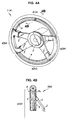
- the steering wheel 1 which has been subjected to the liquid pressure transfer printing will be described with reference to Figs. 4A and 4B by way of example.
- the steering wheel 1 includes a boss section 2 acting as a centre of rotational movement of the steering wheel 1, spoke sections 3 arranged so as to radially extend from the boss section 2, and a rim section 4 connected to a distal end of each of the spoke sections 3 and formed to have a substantially annular shape.
- the rim section 4 as shown in Fig. 4A, includes a long rim portion 41 of an elongated arcuate shape (positioned on an upper side in Fig. 4A), a short rim portion 42 of a short arcuate shape (positioned on a lower side in Fig.
- the long rim portion 41 and short rim portion 42 have a transfer pattern P specifically intended for the workpiece W such as a woodgrain pattern, a straight grain pattern or the like applied thereto and is formed thereon with a topcoat.
- the grip portions 43 are each connected to the spoke sections 3 which extend from the boss section 2. It is considered that the spoke sections 3 cause forces which are different from those acting on the other portions such as the long rim portion 41 and short rim portion 42 to act on the transfer film F during the transfer, resulting in a failure to permit liquid pressure transfer printing like that carried out on the other portions to be attained on the grip portions 43.
- a suitable material such as leather or the like
- techniques of wrapping a suitable material such as leather or the like around the grip portions 43 may be employed after transfer printing, to thereby hide printing applied to the grip portions 43 or apply a special decoration effect or a feel of grip to the grip portions.
- printing applied to the grip portions 43 adversely affects an appearance of the product or causes any problem, such techniques may be eliminated.
- they may be covered with any suitable masking material in advance.
- the transfer pattern P specifically intended for the workpiece W or steering wheel 1A is transferred to the rim section 4, wherein the illustrated embodiment permits pattern distortion to be inconspicuous as compared with the prior art.
- the transfer pattern P is substantially formed to have an annular shape in correspondence to a configuration of the steering wheel 1A. More particularly, in a diametric section of the rod-like element of the steering wheel 1A or a section of the rod-like element of the steering wheel taken in a diametric direction of the rod-like element, distortion of the transfer pattern P is varied depending on a position on a circumference of the diametric section of the rod-like element.
- the pattern distortion in a circumferential direction of the whole steering wheel 1A is substantially the same irrespective of positions thereof. This permits the pattern distortion on the whole steering wheel 1A to be inconspicuous as a whole.
- the transfer pattern P is so arranged that a joint line Pa of the transfer pattern P is positioned on a rear surface of the steering wheel 1 which is substantially out of sight of a driver when the steering wheel is mounted in a vehicle.
- the liquid pressure transfer printing apparatus 10 includes a transfer bath 11, a transfer film storage unit (not shown) and a workpiece holding unit 13.
- the transfer bath 11 has a transfer liquid L stored therein and a transfer film F is supported on a surface of the transfer liquid L while being floated thereon.
- the transfer films formed in individual sheets are fed to the transfer bath 11 one by one by hand so as to be floated on the transfer liquid L, so that the transfer liquid L is always kept stationary.
- the transfer film storage unit is constructed so as to permit the transfer films F to be taken out thereof one by one.
- the transfer film F may be formed to have a rectangular configuration as shown in each of Figs. 3A to 3C by way of example.
- the transfer film F includes a film body which has a transfer operation surface defined thereon.
- the transfer operation surface has the transfer pattern P for decoration formed only on a required position thereof in correspondence to a configuration of the apparent plane R of the workpiece W.
- the transfer pattern p is formed to have a substantially annular shape in correspondence to the configuration of the rim section 4 of the steering wheel 1.
- the transfer film F is suitably provided thereon with reference position marks M which permit relative positioning or registration between the transfer pattern P and the workpiece W to be carried out therethrough.
- the reference position marks M include a cross-like mark arranged on a substantially central position of the transfer pattern, four radial marks arranged at substantially equal angular intervals on an outside of the transfer pattern P, and the like by way of example, as shown in each of Figs. 3A to 3C.
- a transfer film F shown in Fig. 3A is adapted to be directed to decoration of the workpiece W carried out when the workpiece W is vertically lowered to the surface of the transfer liquid L while maintaining an approach attitude angle ⁇ of the workpiece W at 0°.
- the transfer film F of Fig. 3A has a transfer pattern P of a substantially concentric shape formed thereon at high accuracy.
- a transfer film F shown in Fig. 3B is directed to the decoration when the workpiece W is vertically lowered to the liquid surface while maintaining the approach attitude angle ⁇ at a suitable degree.
- the transfer film F of Fig. 3B corresponds to that shown in Fig. 1.
- FIG. 3B has a transfer pattern P which is formed to have a substantially annular shape provided thereon, wherein a major axis Ac and a minor axis At thereof extend in a vertical direction and a horizontal direction of Fig. 3B, respectively.
- a transfer film F shown in Fig. 3C is directed to decoration of the workpiece W when it is obliquely lowered to the liquid surface while maintaining an approach attitude angle ⁇ thereof at a suitable degree.
- the transfer film F corresponds to that described hereinafter with reference to Fig. 2.
- the transfer film F of Fig. 3C has a transfer pattern P formed to have a substantially annular shape wherein a minor axis At and a major axis Ac thereof extend in a vertical direction and a horizontal direction of Fig.
- substantially annular shape indicates such configurations as shown in Figs. 3A to 3C.
- the substantially annular shapes include a substantially complete annular shape as shown in Fig. 3A, as well as somewhat deformed annular shapes as shown in Figs. 3B and 3C.
- the transfer film F shown in each of Figs. 3A to 3C has only one transfer pattern P printed thereon. Alternatively, the transfer film may have a plurality of transfer patterns P printed thereon.
- forming the transfer pattern P into a substantially annular shape for the purpose of transferring, for example, a woodgrain pattern to the workpiece is carried out by subjecting an image of a woodgrain actually photographed to image processing by means of a computer or preparing a picture of a woodgrain directly by means of a computer, to thereby convert a pattern to be transferred into pattern data of a plane rectangular shape. Then, the plane rectangular pattern data thus converted are converted into pattern data of a round or ring-like shape on the computer, resulting in the transfer pattern P being formed to have a substantially annular shape.
- the plane rectangular pattern before the conversion is represented in a coordinate system containing X and Y coordinate axes which are perpendicular to each other as shown in Fig. 7, the conversion permits the X axis to be converted into a circumferential direction and the Y axis to be converted into a radial direction, resulting in the transfer pattern P of a substantially annular shape being provided. It is of course that operation of joining opposite ends of the plane rectangular shape to each other is carried out together with suitable image processing for rendering the joint inconspicuous such as connection of woodgrain lines to each other.
- the above description has been made on conversion of the transfer pattern into a round shape carried out immediately after taking in the transfer pattern as the pattern data of a plane rectangular shape.
- the pattern data photographed is too small to be developed in the circumferential direction.
- the pattern data of a plane rectangular shape indicated by solid lines shown in Fig. 7 have a dimension in the X axis direction sufficient to be converted into the circumferential direction.
- the pattern data having such a large size is not necessarily photographed.
- an approach may be employed which is constructed so as to introduce pattern data of a small size readily photographed into an image processing unit and repeat the pattern data to prepare plane rectangular pattern data of a large size desired.
- Another approach which may be employed is to introduce pattern data of a small size into an image processing unit and then independently multiply a longitudinal dimension of the pattern data and a lateral dimension thereof on a screen of the unit to obtain plane rectangular pattern data of a desired size. Repeating of such small-sized pattern data for formation of such plane rectangular pattern data of a desired size may be carried out on the same pattern. Alternatively, patterns different from each other may be connected to each other. The operation of multiplying the longitudinal dimension and lateral dimension independently from each other is effective to not only conversion of the pattern data into a desired size but, for example, setting of density of woodgrain lines at a suitable level.
- the workpiece holding unit 13 functions to immerse the steering wheel 1A into the transfer liquid L while holding it thereon.
- an approach attitude angle ⁇ defined between the apparent plane R of the workpiece W and the surface of the transfer liquid L is set to be within a range of ⁇ 15° based on a horizontal direction.
- the symbols "+” and “-” referred to herein do not have any specific definition. They merely mean that one rotational direction from a certain reference position indicates "+” and the other rotational direction indicates "-”.
- the workpiece W is immersed in the transfer liquid L in a vertical direction as shown in Fig. 1A.
- a direction of immersion of the workpiece W may be suitably varied.
- the direction of immersion is indicated by an angle ⁇ between the direction of immersion and a line normal to the surface of the transfer liquid, which angle is defined to be an immersion angle herein.
- the immersion angle is defined to be 0° that is, the workpiece is vertically lowered.
- the approach attitude angle ⁇ and immersion angle ⁇ are each suitably set depending on various factors such as a size of the transfer pattern P, a size of the steering wheel 1A, a thickness of the rod-like element, and the like. However, the angles set are not necessarily kept constant during transfer of the transfer pattern to the workpiece.
- the angle may be suitably varied after start of the immersion.
- the approach attitude angle ⁇ and immersion angle ⁇ are set to be 10° and 20°, respectively.
- liquid pressure transfer printing on the workpiece such as a steering wheel or the like will be described in relation to operation of the liquid pressure transfer printing apparatus 10 thus constructed.
- the transfer film F is fed onto the transfer liquid L in the transfer bath 11 while an activator is coated on a surface of the transfer film F to which a transfer ink is applied.
- the activator may be made by, for example, mixing a resin material, a pigment, a solvent, a plasticizer and the like with each other at suitable ratios.
- a solvent such as a thinner or the like may be merely used as the activator.
- the term "activators" referred to herein include a thinner and the like.
- the transfer film F thus coated thereon with the activator absorbs water, to thereby be softened and swollen, resulting in it somewhat extending in all directions.
- Coating of the activator on the transfer film F is for the reason that the transfer film F is normally stored while the applied transfer ink is kept dry.
- the coating permits the ink coated surface of the transfer film F to be provided with stickiness, so that the ink on the transfer film F may be transferred.
- coating of the activator on the transfer film F may be carried out after feeding of the transfer film F onto the transfer liquid L as well.
- the terms "the activator is coated on the transfer film to provide the ink coated surface of the transfer film with stickiness and permit the transfer film to be floated on the transfer liquid" referred to herein or an expression similar thereto does not limit the steps to any specific order.
- coating of the activator may be carried out either after floating of the transfer film F on the transfer liquid or prior thereto.
- the workpiece W or steering wheel 1A is so set that a front surface thereof defined at the time when it is mounted in a vehicle is kept facing the transfer film F. This permits the joint line Pa of the transfer film F to be positioned on a side of a rear surface of the steering wheel which is substantially out of sight of a driver. Then, the steering wheel 1A is immersed in the transfer liquid L while being suitably maintained at a approach attitude angle ⁇ and an immersion angle ⁇ by the workpiece holding unit 13.
- the approach attitude angle ⁇ and immersion angle ⁇ are not necessarily kept constant during the transfer.
- the angles ⁇ and ⁇ may be suitably varied depending on the apparent plane R formed or the like after start of the immersion as well.
- the transfer film F may be provided thereon with the reference position marks M for relative registration between the transfer pattern P and the workpiece W.
- Such arrangement of the reference position marks M permits a position at which immersion of the steering wheel 1A is started to be readily determined.
- the transfer film F When the steering wheel 1A is immersed in the transfer liquid L, the transfer film F is continuously bonded to the steering wheel 1A, so that the transfer pattern P may be transferred to the steering wheel 1A while keeping distortion of the pattern P inconspicuous.
- the transfer may be carried out as shown in Figs. 5A to 5C by way of example. More particularly, the transfer film F circumferentially surrounds the rod-like element continuously from a bottom of the rod-like element to a top thereof on the basis of a diametric section of the rod-like element with progress of immersion of the steering wheel 1A in the transfer liquid L, so that the transfer film F ultimately forms the joint line Pa when it reaches the rear surface side of the steering wheel 1A. Then, the joint line Pa is formed on a whole circumference of the rear surface of the steering wheel 1A, resulting in the transfer being substantially completed.
- a radius of the rod-like element projected on a horizontal plane is gradually decreased from the lowermost point P0 to the innermost peripheral point P2 and gradually increased from the innermost peripheral point P2 to the uppermost point P1.
- the radius of the rod-like element projected on a horizontal plane is gradually increased from the lowermost point P0 to the outermost peripheral point P3 and gradually decreased from the outermost peripheral point P3 to the uppermost point P1.
- the transfer pattern P In order to eliminate distortion of the transfer pattern over the whole circumference or periphery of the diametric section of the rod-like element of the steering wheel 1A, the transfer pattern P would be preferably formed so as to permit such a radius of the rod-like element projected on a horizontal plane to be substantially exactly reproduced.
- the transfer pattern P to be printed is formed to have a substantially annular shape so that the radius projected on a horizontal plane is increased in one direction toward an outside of the transfer pattern. This of course causes the transfer pattern to be subject to distortion, so that a degree of pattern distortion on the circumference or periphery of the diametric section of the rod-like element is of course varied depending on a position on the circumference of the section.
- the transfer film F is softened and swollen due to immersion thereof in the transfer liquid L, resulting in substantially extending in all directions, so that the lowermost point P0, uppermost point P1, innermost peripheral point P2 and outermost peripheral point P3 are substantially identical in pattern distortion in a peripheral or circumferential direction of the whole rod-like element with each other. This permits the pattern distortion on the whole steering wheel 1A to be inconspicuous.
- the steering wheel 1A which has been thus subjected to the liquid pressure transfer printing has a residue of the transfer film F which has not been dissolved in the transfer liquid L adhered thereto.
- the steering wheel 1A is subjected to washing by showering or the like, followed by drying.
- the steering wheel 1A having the transfer pattern thus printed thereon provides a decorated product in accordance with an embodiment of the present invention.
- a transparent topcoat is formed thereon by spraying or the like.
- the topcoat thus formed may be subjected to polishing by buffing or the like.
- the transfer films F formed in individual sheets are fed one by one by hand to the transfer bath 11 in which the transfer liquid L is kept stationary so that they may be floated on the transfer liquid L.
- the present invention may be constructed in such a manner that a transfer film F is continuously fed to the transfer bath 11 in which the transfer liquid L is kept flowing.
- the steering wheel 1A may be vertically lowered to the transfer bath 11.
- the steering wheel may be obliquely lowered to the transfer bath by means of a conveyor of an inverted triangular configuration, an articulated robot or the like.
- coating of the active agent on the transfer film F may be carried out either before feeding of the transfer film F to the transfer bath 11 or thereafter.
- FIG. 6 another embodiment of the present invention is illustrated.
- the embodiment shown in Fig. 6 is constructed so as to continuously feed a transfer film F to a transfer bath 11.
- the transfer bath 11 is provided thereon with a circulation pipe line 14 and a pump 15, so that a transfer liquid L may be slowly circulated as indicated by an arrow in Fig. 6.
- the transfer bath 11 is provided on each of opposite side ends thereof with a guide chain 16.
- the transfer bath 11 is provided with a fan unit 17, which is positioned on an upstream side of the transfer liquid L.
- the transfer liquid L circulated, the guide chains 16, the fan unit 17 and the like cooperate with each other to permit the transfer film F floatedly supported on a surface of the transfer liquid L to be carried toward a workpiece W or a steering wheel 1A while preventing waving of the transfer liquid L.
- a transfer film feed unit 12 is substituted for the transfer film storage unit incorporated in the embodiment described above.
- the transfer film feed unit 12 includes a film roll 18 constituted by winding a water-soluble transfer film F in a roll-like manner, a solvent tank 19 having an activator S stored therein and feed rollers 20, wherein the transfer film F delivered from the film roll 18 is activated by the activator S in the solvent tank 19 and then continuously fed to the transfer bath 11.
- the present invention permits a workpiece such as a steering wheel or the like including a rod-like element curved to form an apparent plane to be readily and positively decorated with a transfer pattern specifically intended for the workpiece.
- the present invention permits the approach attitude angle and/or immersion angle to be optimumly set depending on a type of the transfer pattern, as well as a size of the workpiece, a configuration thereof and the like.
- the transfer printing may be carried out while rendering the pattern distortion inconspicuous.
Landscapes
- Engineering & Computer Science (AREA)
- Chemical & Material Sciences (AREA)
- Combustion & Propulsion (AREA)
- Transportation (AREA)
- Mechanical Engineering (AREA)
- Decoration By Transfer Pictures (AREA)
- Printing Methods (AREA)
- Steering Controls (AREA)
Abstract
Description
- This invention relates to a liquid pressure transfer method, and more particularly to a liquid pressure transfer printing method for applying a pattern for decoration specifically intended for a workpiece such as a steering wheel for an automobile or the like which includes a rod-like element curved to form a predetermined apparent plane to the workpiece.
- For example, a steering wheel for an automobile has a core made of a metal material so as to exhibit strength at a predetermined level or more. The core is provided therearound with a grip surface, which is formed of a material such as a plastic material, a wooden material, a leather material or the like which is selected depending on requirements such as operability of the steering wheel, decorative characteristics thereof and the like. For example, a steering wheel provided thereon with a wooden surface is evaluated to be a high-quality article, because it exhibits both satisfactory operability and decorative characteristics and requires considerable labour and time for manufacturing. However, a recent tendency of reconsidering easygoing use of a natural material in view of protection of a natural environment and a demand for reduction of a manufacturing cost lead to development of liquid pressure transfer printing techniques of carrying out transfer printing on a plastic steering wheel material in place of a wooden steering wheel material to apply a woodgrain pattern for decoration thereto.
- Application of a decorative pattern to a workpiece by liquid pressure transfer permits formation of a natural pattern which exhibits satisfactory conformability to a configuration of the workpiece, resulting in it being extensively practiced on a variety of workpieces. However, application of such liquid pressure transfer to, for example, a steering wheel encounters some important problems. A conventional steering wheel made of a wooden material is manufactured by subjecting two wooden rod-like materials which are semicircular in section to a treatment by moistening, heating and the like to bend them into an annular shape and then bonding them to each other while interposing a core therebetween. Thus, of course the wooden materials are each so arranged that a straight grain extends in a circumferential direction of the steering wheel. Such arrangement of the straight grain permits a user to have a sense of security or a sense of reliability.
- Unfortunately, in application of a decorative pattern to a workpiece by liquid pressure transfer, a transfer film having a transfer pattern formed thereon is supported on a surface of a transfer liquid while being floated thereon, so that exact positioning or registration between the transfer film and the workpiece is relatively difficult. Thus, in the prior art, a decorative pattern such as a woodgrain pattern, a natural stone pattern, a carbon fibre pattern or the like which is continuously formed is arranged all over the transfer film so as to allow misregistration which occurs between the transfer film and the workpiece, resulting in a decorative pattern similar to a natural material being provided irrespective of a portion of the pattern transferred to the workpiece. Nevertheless, development of techniques of reproducing a transfer pattern specifically intended for a desired product such as, for example, techniques of arranging a straight grain pattern in a circumferential direction of a steering wheel, has still been demanded.
- The present invention has been made in view of the foregoing disadvantage of the prior art.
- Accordingly, it is an object of the present invention to provide a liquid pressure transfer method which is capable of applying a decorative pattern specifically intended for a specific or desired workpiece such as a steering wheel or the like to the workpiece.
- It is another object of the present invention to provide a transfer film which is capable of facilitating application of a decorative pattern specifically intended for a workpiece such as a steering wheel or the like to the workpiece.
- It is a further object of the present invention to provide a product decorated according to the liquid pressure transfer method described above.
- In accordance with one aspect of the present invention, a liquid pressure transfer method for carrying out liquid pressure transfer printing on a workpiece such as a steering wheel is provided. The liquid pressure transfer method includes the step of supporting a transfer film on a surface of a transfer liquid while floating it thereon. The transfer film has a transfer pattern for decoration printed thereon. The liquid pressure transfer method also includes the step of downwardly immersing a workpiece in the transfer liquid to transfer the transfer pattern to a surface of the workpiece, to thereby decorate the workpiece. The workpiece includes a rod-like element curved into a loop-like shape, resulting in it being formed with an apparent plane which permits the workpiece to be recognized as a whole. The transfer pattern is formed to have a configuration corresponding to a configuration of the apparent plane of the workpiece and arranged on a required position of the transfer film. The workpiece is operated so as to approach the transfer film from a position above the transfer pattern corresponding to the transfer pattern and then be immersed in the transfer liquid, so that the transfer film bonds to the rod-like element of the workpiece in a manner to circumferentially surround the rod-like element continuously from a bottom of the rod-like element to a top thereof with respect to a diametric section of the rod-like element, resulting in the transfer pattern being transferred to at least the rod-like element of the workpiece.
- The liquid pressure transfer method thus constructed permits the workpiece such as a steering wheel or the like which includes the rod-like element curved to form a predetermined apparent plane to be readily and positively decorated with a transfer pattern specifically intended for the workpiece.
- In a preferred embodiment of the present invention, an approach attitude angle defined between the apparent plane of the workpiece and the surface of the transfer liquid is set to be within a range of ±15°. This permits the optimum approach attitude angle to be set depending on a type of the transfer pattern, as well as a size of the workpiece, a configuration thereof and the like.
- In a preferred embodiment of the present invention, the workpiece is immersed in the transfer liquid in a substantially vertical direction. Such vertical lowering of the workpiece to the surface of the transfer liquid facilitates transfer of the transfer pattern to the workpiece.
- In a preferred embodiment of the present invention, the transfer film is provided thereon with reference position marks for enabling relative registration between the transfer pattern and the workpiece. This permits positioning or registration between the transfer pattern and the workpiece to be readily attained while preventing misregistration of the transfer film.
- In accordance with another aspect of the present invention, a transfer film is provided. The transfer film includes a film body which has a transfer operation surface defined thereon. The transfer operation surface has a predetermined transfer pattern previously printed thereon in transfer ink. When transfer is to be carried out, the transfer operation surface is coated thereon with an activator to permit a portion of the transfer operation surface to which the transfer ink is applied to exhibit stickiness and the transfer film is supported on a surface of a transfer liquid while being floated thereon. The transfer pattern is transferred to a surface of a workpiece by a liquid pressure produced when the workpiece is downwardly immersed in the transfer liquid. The transfer film is applied to the workpiece including a rod-like element curved into a loop-like shape, resulting in the workpiece being formed with an apparent plane which permits the workpiece to be recognized as a whole. The transfer pattern is formed to have a configuration corresponding to a configuration of the apparent plane of the workpiece and arranged on a required position of the transfer film. The transfer film thus constructed permits the transfer pattern specifically intended for the workpiece to be readily applied to the workpiece, to thereby facilitate decoration of the workpiece.
- In a preferred embodiment of the present invention, the workpiece is a steering wheel. The transfer pattern is formed to have a substantially annular shape in correspondence to the apparent plane of the steering wheel. Thus, in the present invention, although distortion of the pattern is varied depending on a position on a circumference of a diametric section of the rod-like element of the workpiece, the pattern distortion in a circumferential direction of the whole steering wheel is substantially the same irrespective of a position on the rod-like element in the circumferential direction thereof. Thus, the transfer printing may be carried out while rendering the pattern distortion inconspicuous.
- In a preferred embodiment of the present invention, the transfer pattern is formed to have a substantially annular shape by taking in pattern data of a plane rectangular shape and then converting into pattern data of a round shape. This permits the transfer pattern specifically intended for the workpiece to be more exactly reproduced on the workpiece.
- In accordance with a further aspect of the present invention, there is provided a decorated product to which a predetermined decorative pattern is applied by subjecting a workpiece such as a steering wheel or the like including a rod-like element to liquid pressure transfer printing in which the workpiece is downwardly immersed in a transfer liquid which supports a transfer film having a transfer pattern for decoration printed thereon on a surface thereof while floating it thereon, so that the transfer pattern is applied to at least the rod-like element of the workpiece. The workpiece is operated so as to permit the transfer pattern to be printed on the rod-like element of the workpiece in a manner to circumferentially surround the rod-like element continuously from a bottom of the rod-like element to a top thereof with respect to a diametric section of the rod-like element, resulting in transfer of the transfer pattern to the workpiece being carried out according to the above-described liquid pressure transfer method while ensuring exact reproducibility of the transfer pattern.
- Such construction permits the transfer pattern to be more exactly reproduced on a variety of workpieces of a closed loop shape or an open loop shape including, for example, a hula hoop, rings in gymnastic, a towel ring, a chair back, a handrail and the like in addition to the steering wheel while minimizing distortion of the transfer pattern.
- These and other objects and many of the attendant advantages of the present invention will be readily appreciated as the same becomes better understood by reference to the following detailed description of preferred embodiments of the invention when considered in connection with the accompanying drawings; wherein:
- Fig. 1A is a schematic side elevation view showing an apparatus which is adapted to practice a liquid pressure transfer method according to an embodiment of the present invention wherein an immersion angle is set to be 0° by way of example;
- Fig. 1B is an enlarged partial cross sectional view
of
part 1B of Fig. 1A; - Fig. 2 is a schematic side elevation view showing the apparatus which is adapted to practice a liquid pressure transfer method according to an embodiment of the present invention wherein the immersion angle is set to be 20°;
- Figs. 3A to 3C each are a plan view showing a transfer pattern formed on a transfer film;
- Fig. 4A is a perspective view showing a steering wheel which is an example of a decorated product according to an embodiment of the present invention;
- Fig. 4B is a sectional view taken along
line 4B-4B of Fig. 4A; - Figs. 5A to 5C are schematic views showing steps of liquid pressure transfer by stages, respectively;
- Fig. 6 is a schematic side elevation view showing a unit for continuously feeding a transfer film to a transfer bath in which a transfer liquid flows; and
- Fig. 7 is a schematic view showing a procedure for converting pattern data of a rectangular shape into pattern data of an annular shape.
-
- Now, preferred embodiments of the present invention will be described in detail with reference to the accompanying drawings. The following description will be first made of a workpiece to be decorated according to an embodiment of the present invention. Then, a liquid pressure transfer printing apparatus for carrying out liquid pressure transfer printing on such a workpiece is schematically described. Subsequently, a liquid pressure transfer printing method according to an embodiment of the present invention will be described together with a manner of operation of the liquid pressure transfer printing apparatus.
- A workpiece designated by reference character W in Figs. 1A, 1B and 2 includes a rod-like element formed to be curved to define a predetermined apparent plane R identifiable with the workpiece as a whole. Thus, the workpieces to which the present invention is applicable may include, for example, a steering wheel to be mounted on a vehicle or the like, as well as products of an annular shape, a substantially O-shape or the like which form a closed loop such as a hula hoop, rings in gymnastics, a towel ring and the like and products of a substantially U-shape which form an open loop such as a chair back and the like. Further, the workpieces may include products such as a handrail for stairs and the like wherein two loop-like members are connected together through one or two straight members.
- The apparent plane R is defined as a plane literally when the present invention is applied to a steering wheel as the workpiece W. However, it is not necessarily literally defined as a plane, for example, when the present invention is applied to a chair back as the workpiece W. In this instance, the apparent plane R may often be defined so as to have somewhat of a curvature. Thus, in at least preferred embodiments the workpiece may include a curved rod-like element or elements lying substantially within a plane.
- Also, the illustrated embodiment will be described essentially in connection with the case that the present invention is applied to a steering wheel as the workpiece W. Thus, when it is required to distinguish a steering wheel before the liquid pressure transfer printing in accordance with an embodiment of the present invention and that after the transfer printing from each other, a steering wheel which has been subjected to the liquid pressure transfer printing is designated by reference character 1 and that before the printing is designated by 1A.
- Now, the steering wheel 1 which has been subjected to the liquid pressure transfer printing will be described with reference to Figs. 4A and 4B by way of example. The steering wheel 1 includes a
boss section 2 acting as a centre of rotational movement of the steering wheel 1, spokesections 3 arranged so as to radially extend from theboss section 2, and arim section 4 connected to a distal end of each of thespoke sections 3 and formed to have a substantially annular shape. Therim section 4, as shown in Fig. 4A, includes along rim portion 41 of an elongated arcuate shape (positioned on an upper side in Fig. 4A), ashort rim portion 42 of a short arcuate shape (positioned on a lower side in Fig. 4A), and twogrip portions 43 for connecting thelong rim portion 41 andshort rim portion 42 to each other therethrough (positioned on both lateral sides in Fig. 4A). Thelong rim portion 41 andshort rim portion 42 have a transfer pattern P specifically intended for the workpiece W such as a woodgrain pattern, a straight grain pattern or the like applied thereto and is formed thereon with a topcoat. - The
grip portions 43 are each connected to thespoke sections 3 which extend from theboss section 2. It is considered that thespoke sections 3 cause forces which are different from those acting on the other portions such as thelong rim portion 41 andshort rim portion 42 to act on the transfer film F during the transfer, resulting in a failure to permit liquid pressure transfer printing like that carried out on the other portions to be attained on thegrip portions 43. Thus, for example, techniques of wrapping a suitable material such as leather or the like around thegrip portions 43 may be employed after transfer printing, to thereby hide printing applied to thegrip portions 43 or apply a special decoration effect or a feel of grip to the grip portions. However, unless printing applied to thegrip portions 43 adversely affects an appearance of the product or causes any problem, such techniques may be eliminated. Also, when it is not desired to apply liquid pressure transfer printing to thegrip portions 43, they may be covered with any suitable masking material in advance. - In printing applied to the
rim section 4, the transfer pattern P specifically intended for the workpiece W or steering wheel 1A is transferred to therim section 4, wherein the illustrated embodiment permits pattern distortion to be inconspicuous as compared with the prior art. This is due to the fact that the transfer pattern P is substantially formed to have an annular shape in correspondence to a configuration of the steering wheel 1A. More particularly, in a diametric section of the rod-like element of the steering wheel 1A or a section of the rod-like element of the steering wheel taken in a diametric direction of the rod-like element, distortion of the transfer pattern P is varied depending on a position on a circumference of the diametric section of the rod-like element. However, the pattern distortion in a circumferential direction of the whole steering wheel 1A is substantially the same irrespective of positions thereof. This permits the pattern distortion on the whole steering wheel 1A to be inconspicuous as a whole. The transfer pattern P is so arranged that a joint line Pa of the transfer pattern P is positioned on a rear surface of the steering wheel 1 which is substantially out of sight of a driver when the steering wheel is mounted in a vehicle. - Now, a liquid pressure
transfer printing apparatus 10 will be described with reference to Fig. 1A by way of example. The liquid pressuretransfer printing apparatus 10 includes atransfer bath 11, a transfer film storage unit (not shown) and aworkpiece holding unit 13. - The
transfer bath 11 has a transfer liquid L stored therein and a transfer film F is supported on a surface of the transfer liquid L while being floated thereon. In the illustrated embodiment, the transfer films formed in individual sheets are fed to thetransfer bath 11 one by one by hand so as to be floated on the transfer liquid L, so that the transfer liquid L is always kept stationary. - The transfer film storage unit is constructed so as to permit the transfer films F to be taken out thereof one by one.
- The transfer film F may be formed to have a rectangular configuration as shown in each of Figs. 3A to 3C by way of example. The transfer film F includes a film body which has a transfer operation surface defined thereon. The transfer operation surface has the transfer pattern P for decoration formed only on a required position thereof in correspondence to a configuration of the apparent plane R of the workpiece W. In the illustrated embodiment, the transfer pattern p is formed to have a substantially annular shape in correspondence to the configuration of the
rim section 4 of the steering wheel 1. Also, the transfer film F is suitably provided thereon with reference position marks M which permit relative positioning or registration between the transfer pattern P and the workpiece W to be carried out therethrough. In the illustrated embodiment, the reference position marks M include a cross-like mark arranged on a substantially central position of the transfer pattern, four radial marks arranged at substantially equal angular intervals on an outside of the transfer pattern P, and the like by way of example, as shown in each of Figs. 3A to 3C. - A transfer film F shown in Fig. 3A is adapted to be directed to decoration of the workpiece W carried out when the workpiece W is vertically lowered to the surface of the transfer liquid L while maintaining an approach attitude angle α of the workpiece W at 0°. The transfer film F of Fig. 3A has a transfer pattern P of a substantially concentric shape formed thereon at high accuracy. A transfer film F shown in Fig. 3B is directed to the decoration when the workpiece W is vertically lowered to the liquid surface while maintaining the approach attitude angle α at a suitable degree. Thus, the transfer film F of Fig. 3B corresponds to that shown in Fig. 1. The transfer film F of Fig. 3B has a transfer pattern P which is formed to have a substantially annular shape provided thereon, wherein a major axis Ac and a minor axis At thereof extend in a vertical direction and a horizontal direction of Fig. 3B, respectively. A transfer film F shown in Fig. 3C is directed to decoration of the workpiece W when it is obliquely lowered to the liquid surface while maintaining an approach attitude angle α thereof at a suitable degree. The transfer film F corresponds to that described hereinafter with reference to Fig. 2. Thus, the transfer film F of Fig. 3C has a transfer pattern P formed to have a substantially annular shape wherein a minor axis At and a major axis Ac thereof extend in a vertical direction and a horizontal direction of Fig. 3C, respectively. The term "substantially annular shape" referred to herein indicates such configurations as shown in Figs. 3A to 3C. Thus, the substantially annular shapes include a substantially complete annular shape as shown in Fig. 3A, as well as somewhat deformed annular shapes as shown in Figs. 3B and 3C. Also, the transfer film F shown in each of Figs. 3A to 3C has only one transfer pattern P printed thereon. Alternatively, the transfer film may have a plurality of transfer patterns P printed thereon.
- Further, forming the transfer pattern P into a substantially annular shape for the purpose of transferring, for example, a woodgrain pattern to the workpiece is carried out by subjecting an image of a woodgrain actually photographed to image processing by means of a computer or preparing a picture of a woodgrain directly by means of a computer, to thereby convert a pattern to be transferred into pattern data of a plane rectangular shape. Then, the plane rectangular pattern data thus converted are converted into pattern data of a round or ring-like shape on the computer, resulting in the transfer pattern P being formed to have a substantially annular shape. Thus, it will be noted that when the plane rectangular pattern before the conversion is represented in a coordinate system containing X and Y coordinate axes which are perpendicular to each other as shown in Fig. 7, the conversion permits the X axis to be converted into a circumferential direction and the Y axis to be converted into a radial direction, resulting in the transfer pattern P of a substantially annular shape being provided. It is of course that operation of joining opposite ends of the plane rectangular shape to each other is carried out together with suitable image processing for rendering the joint inconspicuous such as connection of woodgrain lines to each other.
- The above description has been made on conversion of the transfer pattern into a round shape carried out immediately after taking in the transfer pattern as the pattern data of a plane rectangular shape. However, for example, it may be considered that the pattern data photographed is too small to be developed in the circumferential direction. More particularly, the pattern data of a plane rectangular shape indicated by solid lines shown in Fig. 7 have a dimension in the X axis direction sufficient to be converted into the circumferential direction. However, the pattern data having such a large size is not necessarily photographed. In order to solve the problem, an approach may be employed which is constructed so as to introduce pattern data of a small size readily photographed into an image processing unit and repeat the pattern data to prepare plane rectangular pattern data of a large size desired. Another approach which may be employed is to introduce pattern data of a small size into an image processing unit and then independently multiply a longitudinal dimension of the pattern data and a lateral dimension thereof on a screen of the unit to obtain plane rectangular pattern data of a desired size. Repeating of such small-sized pattern data for formation of such plane rectangular pattern data of a desired size may be carried out on the same pattern. Alternatively, patterns different from each other may be connected to each other. The operation of multiplying the longitudinal dimension and lateral dimension independently from each other is effective to not only conversion of the pattern data into a desired size but, for example, setting of density of woodgrain lines at a suitable level.
- The
workpiece holding unit 13 functions to immerse the steering wheel 1A into the transfer liquid L while holding it thereon. In the immersion, an approach attitude angle α defined between the apparent plane R of the workpiece W and the surface of the transfer liquid L is set to be within a range of ±15° based on a horizontal direction. The symbols "+" and "-" referred to herein do not have any specific definition. They merely mean that one rotational direction from a certain reference position indicates "+" and the other rotational direction indicates "-". Also, in the illustrated embodiment, the workpiece W is immersed in the transfer liquid L in a vertical direction as shown in Fig. 1A. However, a direction of immersion of the workpiece W may be suitably varied. In the present invention, the direction of immersion is indicated by an angle β between the direction of immersion and a line normal to the surface of the transfer liquid, which angle is defined to be an immersion angle herein. When the workpiece is immersed in the normal direction as shown in Fig. 1A, the immersion angle is defined to be 0° that is, the workpiece is vertically lowered. The approach attitude angle α and immersion angle β are each suitably set depending on various factors such as a size of the transfer pattern P, a size of the steering wheel 1A, a thickness of the rod-like element, and the like. However, the angles set are not necessarily kept constant during transfer of the transfer pattern to the workpiece. For example, when the apparent plane R of the workpiece W somewhat has a curvature, the angle may be suitably varied after start of the immersion. For example, in the immersion shown in Fig. 2, the approach attitude angle α and immersion angle β are set to be 10° and 20°, respectively. - Now, liquid pressure transfer printing on the workpiece such as a steering wheel or the like will be described in relation to operation of the liquid pressure
transfer printing apparatus 10 thus constructed. - First, the transfer film F is fed onto the transfer liquid L in the
transfer bath 11 while an activator is coated on a surface of the transfer film F to which a transfer ink is applied. The activator may be made by, for example, mixing a resin material, a pigment, a solvent, a plasticizer and the like with each other at suitable ratios. Alternatively, a solvent such as a thinner or the like may be merely used as the activator. Thus, the term "activators" referred to herein include a thinner and the like. The transfer film F thus coated thereon with the activator absorbs water, to thereby be softened and swollen, resulting in it somewhat extending in all directions. Coating of the activator on the transfer film F is for the reason that the transfer film F is normally stored while the applied transfer ink is kept dry. Thus, the coating permits the ink coated surface of the transfer film F to be provided with stickiness, so that the ink on the transfer film F may be transferred. Also, coating of the activator on the transfer film F may be carried out after feeding of the transfer film F onto the transfer liquid L as well. Thus, the terms "the activator is coated on the transfer film to provide the ink coated surface of the transfer film with stickiness and permit the transfer film to be floated on the transfer liquid" referred to herein or an expression similar thereto does not limit the steps to any specific order. Thus, in the present invention, coating of the activator may be carried out either after floating of the transfer film F on the transfer liquid or prior thereto. - The workpiece W or steering wheel 1A is so set that a front surface thereof defined at the time when it is mounted in a vehicle is kept facing the transfer film F. This permits the joint line Pa of the transfer film F to be positioned on a side of a rear surface of the steering wheel which is substantially out of sight of a driver. Then, the steering wheel 1A is immersed in the transfer liquid L while being suitably maintained at a approach attitude angle α and an immersion angle β by the
workpiece holding unit 13. The approach attitude angle α and immersion angle β are not necessarily kept constant during the transfer. The angles α and β may be suitably varied depending on the apparent plane R formed or the like after start of the immersion as well. Also, the transfer film F, as described above, may be provided thereon with the reference position marks M for relative registration between the transfer pattern P and the workpiece W. Such arrangement of the reference position marks M permits a position at which immersion of the steering wheel 1A is started to be readily determined. - When the steering wheel 1A is immersed in the transfer liquid L, the transfer film F is continuously bonded to the steering wheel 1A, so that the transfer pattern P may be transferred to the steering wheel 1A while keeping distortion of the pattern P inconspicuous. The transfer may be carried out as shown in Figs. 5A to 5C by way of example. More particularly, the transfer film F circumferentially surrounds the rod-like element continuously from a bottom of the rod-like element to a top thereof on the basis of a diametric section of the rod-like element with progress of immersion of the steering wheel 1A in the transfer liquid L, so that the transfer film F ultimately forms the joint line Pa when it reaches the rear surface side of the steering wheel 1A. Then, the joint line Pa is formed on a whole circumference of the rear surface of the steering wheel 1A, resulting in the transfer being substantially completed.
- Now, distortion of the transfer pattern P on the steering wheel 1A will be described. First, it is supposed that on a circumference of the diametric section of the rod-like element of the steering wheel 1A, a lowermost point at which the transfer is first initiated, an uppermost point at which the joint line Pa of the transfer pattern P is formed, an innermost peripheral point positioned between the lowermost point and the uppermost point, and an outermost peripheral point positioned therebetween are designated by reference characters P0, P1, P2 and P3 in Fig. 1B, respectively. In this instance, in a region in which the transfer is carried out from the lowermost point P0 through the innermost peripheral point P2 to the uppermost point P1, a radius of the rod-like element projected on a horizontal plane is gradually decreased from the lowermost point P0 to the innermost peripheral point P2 and gradually increased from the innermost peripheral point P2 to the uppermost point P1. Whereas, in a region where the transfer is carried out from the lowermost point P0 through the outermost peripheral point P3 to the uppermost point P1, the radius of the rod-like element projected on a horizontal plane is gradually increased from the lowermost point P0 to the outermost peripheral point P3 and gradually decreased from the outermost peripheral point P3 to the uppermost point P1.
- In order to eliminate distortion of the transfer pattern over the whole circumference or periphery of the diametric section of the rod-like element of the steering wheel 1A, the transfer pattern P would be preferably formed so as to permit such a radius of the rod-like element projected on a horizontal plane to be substantially exactly reproduced. However, actually this is highly difficult, therefore, actually the transfer pattern P to be printed is formed to have a substantially annular shape so that the radius projected on a horizontal plane is increased in one direction toward an outside of the transfer pattern. This of course causes the transfer pattern to be subject to distortion, so that a degree of pattern distortion on the circumference or periphery of the diametric section of the rod-like element is of course varied depending on a position on the circumference of the section. However, the transfer film F is softened and swollen due to immersion thereof in the transfer liquid L, resulting in substantially extending in all directions, so that the lowermost point P0, uppermost point P1, innermost peripheral point P2 and outermost peripheral point P3 are substantially identical in pattern distortion in a peripheral or circumferential direction of the whole rod-like element with each other. This permits the pattern distortion on the whole steering wheel 1A to be inconspicuous.
- The steering wheel 1A which has been thus subjected to the liquid pressure transfer printing has a residue of the transfer film F which has not been dissolved in the transfer liquid L adhered thereto. Thus, in order to fully remove the residue, the steering wheel 1A is subjected to washing by showering or the like, followed by drying.
- The steering wheel 1A having the transfer pattern thus printed thereon provides a decorated product in accordance with an embodiment of the present invention. However, when it is desired that a portion of the steering wheel which has been subjected to the transfer printing exhibit increased gloss and depth of a colour, a transparent topcoat is formed thereon by spraying or the like. The topcoat thus formed may be subjected to polishing by buffing or the like.
- In the illustrated embodiment, the transfer films F formed in individual sheets are fed one by one by hand to the
transfer bath 11 in which the transfer liquid L is kept stationary so that they may be floated on the transfer liquid L. Alternatively, the present invention may be constructed in such a manner that a transfer film F is continuously fed to thetransfer bath 11 in which the transfer liquid L is kept flowing. In this instance, the steering wheel 1A may be vertically lowered to thetransfer bath 11. Alternatively, the steering wheel may be obliquely lowered to the transfer bath by means of a conveyor of an inverted triangular configuration, an articulated robot or the like. Also, coating of the active agent on the transfer film F may be carried out either before feeding of the transfer film F to thetransfer bath 11 or thereafter. - Referring now to Fig. 6, another embodiment of the present invention is illustrated. The embodiment shown in Fig. 6 is constructed so as to continuously feed a transfer film F to a
transfer bath 11. For this purpose, thetransfer bath 11 is provided thereon with acirculation pipe line 14 and apump 15, so that a transfer liquid L may be slowly circulated as indicated by an arrow in Fig. 6. Also, thetransfer bath 11 is provided on each of opposite side ends thereof with aguide chain 16. Further, thetransfer bath 11 is provided with afan unit 17, which is positioned on an upstream side of the transfer liquid L. Thus, the transfer liquid L circulated, theguide chains 16, thefan unit 17 and the like cooperate with each other to permit the transfer film F floatedly supported on a surface of the transfer liquid L to be carried toward a workpiece W or a steering wheel 1A while preventing waving of the transfer liquid L. - Also, in the embodiment illustrated in Fig. 6, a transfer
film feed unit 12 is substituted for the transfer film storage unit incorporated in the embodiment described above. The transferfilm feed unit 12 includes afilm roll 18 constituted by winding a water-soluble transfer film F in a roll-like manner, asolvent tank 19 having an activator S stored therein andfeed rollers 20, wherein the transfer film F delivered from thefilm roll 18 is activated by the activator S in thesolvent tank 19 and then continuously fed to thetransfer bath 11. - After the transfer film F fed to the
transfer bath 11 which is thus activated is carried to a suitable position, the steering wheel 1A is immersed in thetransfer bath 11 by means of aworkpiece holding unit 13. Operation of transferring a transfer pattern P from the transfer film F to the workpiece W in the embodiment illustrated in Fig. 6 is carried out in substantially the same manner as that in the embodiment described above. - As can be seen from the foregoing, the present invention permits a workpiece such as a steering wheel or the like including a rod-like element curved to form an apparent plane to be readily and positively decorated with a transfer pattern specifically intended for the workpiece.
- Also, the present invention permits the approach attitude angle and/or immersion angle to be optimumly set depending on a type of the transfer pattern, as well as a size of the workpiece, a configuration thereof and the like.
- Further, positioning or registration between the transfer pattern of the transfer film floatedly supported on the transfer liquid and the workpiece is relatively readily attained, to thereby prevent misregistration of the transfer film.
- Moreover, distortion of the pattern is varied depending on a position on the periphery of the diametric section of the rod-like element of the workpiece. However, the pattern distortion is substantially the same irrespective of a position on the circumference of the whole rod-like element. Thus, the transfer printing may be carried out while rendering the pattern distortion inconspicuous.
- While preferred embodiments of the invention have been described with reference to the drawings, obvious modifications and variations are possible in light of the above teachings. It is therefore to be understood that within the scope of the appended claims, the invention may be practiced otherwise than as specifically described.
Claims (9)
- A liquid pressure transfer method comprising the steps of:supporting a transfer film (F) floatingly on a surface of a transfer liquid (L), said transfer film (F) having a transfer pattern (P) for decoration printed thereon; anddownwardly immersing a workpiece (W) in the transfer liquid (L) to transfer the transfer pattern (P) to a surface of the workpiece (W), to thereby decorate the workpiece (W), characterized in that:the workpiece (W) includes a rod-like element (4) curved into a loop-like shape, resulting in it being formed with an apparent plane (R) identifiable with the workpiece (W) as a whole;the transfer pattern (P) is formed to have a configuration corresponding to a configuration of the apparent plane (R) of the workpiece (W) and arranged on a required position of the transfer film (F); andthe workpiece (W) is operated so as to approach the transfer film (F) from a position above the transfer pattern (P) corresponding to the transfer pattern (P) and then be immersed in the transfer liquid (L), so that the transfer film (F) bonds to the rod-like element (4) of the workpiece (W) in a manner to circumferentially surround the rod-like element (4) continuously from a bottom of the rod-like element (4) to a top thereof with respect to a diametric section of the rod-like element (4), resulting in the transfer pattern (P) being transferred to at least the rod-like element (4) of the workpiece (W).
- A liquid pressure transfer method as defined in claim 1, characterized in that an approach attitude angle (α) defined between the apparent plane (R) of the workpiece (W) and the surface of the transfer liquid (L) is set to be within a range of ±15°.
- A liquid pressure transfer method as defined in claim 1 or 2, characterized in that the workpiece (W) is immersed in the transfer liquid (L) in a substantially vertical direction.
- A liquid pressure transfer method as defined in any one of claims 1 to 3, characterized in that the transfer film (F) is provided thereon with reference position marks (M) for enabling relative registration between the transfer pattern (P) and the workpiece (W).
- A transfer film (F) comprising:a film body having a transfer operation surface defined thereon, said transfer operation surface having a predetermined transfer pattern (P) previously printed thereon in transfer ink;
wherein, said transfer film (F) is so adapted that when transfer is to be carried out, said transfer operation surface is coatable thereon with an activator (S) to permit a portion of said transfer operation surface to which said transfer ink is applied to exhibit stickiness, the transfer film (F) is floatingly supportable on a surface of a transfer liquid (L), and said transfer pattern (P) is transferable to a surface of a workpiece (W) by a liquid pressure produced when a said workpiece (W) is downwardly immersed in the transfer liquid (L), characterized in that:the transfer film (F) is adapted to be applied to a workpiece (W) including a rod-like element (4) curved into a loop-like shape having an apparent plane (R) which is identifiable with the workpiece (W) as a whole; andsaid transfer pattern (P) is formed to have a configuration corresponding to a configuration of said apparent plane (R) of said workpiece (W) and arranged on a required position of the transfer film (F). - A transfer film (F) as defined in claim 5, characterized in that the transfer film (F) is adapted to be applied to a workpiece (W) in the form of a steering wheel (1A); andsaid transfer pattern (P) is formed to have a substantially annular shape in correspondence to the apparent plane (R) of the steering wheel (1A).
- A transfer film (F) as defined in claim 5 or 6, characterized in that said transfer pattern (P) is formed to have a substantially annular shape by taking in pattern data of a plane rectangular shape and then converting the data into pattern data of a round shape.
- A decorated product to which a predetermined decorative pattern is applied by subjecting a workpiece (W) including a rod-like element (4) to liquid pressure transfer printing in which the workpiece (W) is downwardly immersed in a transfer liquid (L) which supports floatingly on a surface thereof a transfer film (F) having a transfer pattern (P) for decoration printed thereon, so that the transfer pattern (P) is applied to at least the rod-like element (4) of the workpiece (W), characterized in that:said workpiece (W) is operated so as to permit the transfer pattern (P) to be printed on said rod-like element (4) of said workpiece (W) in a manner to circumferentially surround said rod-like element (4) continuously from a bottom of said rod-like element (4) to a top thereof with respect to a diametric section of said rod-like element (4), resulting in transfer of the transfer pattern (P) to said workpiece (W) being carried out according to the method of any one of claims 1 to 4 while ensuring substantially exact reproducibility of the transfer pattern (P).
- A transfer film (F) comprising:a film body having a transfer operation surface defined thereon, said transfer operation surface having a predetermined transfer pattern (P) previously printed thereon in transfer ink;
wherein, said transfer film (F) is so adapted that when transfer is to be carried out, said transfer operation surface is coatable thereon with an activator (S) to permit a portion of said transfer operation surface to which said transfer ink is applied to exhibit stickiness, the transfer film (F) is floatingly supportable on a surface of a transfer liquid (L), and said transfer pattern (P) is transferable to a surface of a workpiece (W) by a liquid pressure produced when a said workpiece (W) is downwardly immersed in the transfer liquid (L), characterised in that:said transfer pattern (P) is formed to have a predetermined loop-like configuration and is arranged on a predetermined position of the transfer film (F) so as to be transferable to a workpiece (W) of a predetermined loop-like shape.
Applications Claiming Priority (2)
| Application Number | Priority Date | Filing Date | Title |
|---|---|---|---|
| JP27860299A JP2001096993A (en) | 1999-09-30 | 1999-09-30 | Method for liquid-pressure transfer for workpiece such as steering wheel, transfer film applied thereto and decorated product to which this method is applied |
| JP27860299 | 1999-09-30 |
Publications (2)
| Publication Number | Publication Date |
|---|---|
| EP1088676A1 true EP1088676A1 (en) | 2001-04-04 |
| EP1088676B1 EP1088676B1 (en) | 2003-09-10 |
Family
ID=17599569
Family Applications (1)
| Application Number | Title | Priority Date | Filing Date |
|---|---|---|---|
| EP00301593A Expired - Lifetime EP1088676B1 (en) | 1999-09-30 | 2000-02-29 | Liquid pressure transfer method for loop-like workpiece and product decorated thereby |
Country Status (7)
| Country | Link |
|---|---|
| US (2) | US6599579B1 (en) |
| EP (1) | EP1088676B1 (en) |
| JP (1) | JP2001096993A (en) |
| KR (1) | KR100508220B1 (en) |
| CN (1) | CN1202963C (en) |
| DE (1) | DE60005105T2 (en) |
| ES (1) | ES2206138T3 (en) |
Cited By (6)
| Publication number | Priority date | Publication date | Assignee | Title |
|---|---|---|---|---|
| FR2791606A1 (en) * | 1999-04-02 | 2000-10-06 | Youn Soo Cho | Method of image marking on rim of motor vehicle steering wheel uses symmetrical templates to successively etch both side of rim using water pressure |
| US6541074B2 (en) | 2000-08-11 | 2003-04-01 | Cho Youn-Soo | Liquid pressure transfer printing method for steering wheel rim of automobile |
| DE10154732A1 (en) * | 2001-11-09 | 2003-05-22 | Wipak Walsrode Gmbh & Co Kg | Colored decoration transmission system |
| WO2005009748A1 (en) * | 2003-07-25 | 2005-02-03 | Antonio Di Riso | Mdc 2 carbon effect |
| US7141134B2 (en) | 2002-05-29 | 2006-11-28 | Cho Youn-Soo | Method and apparatus for automatically transferring pattern to surface of steering wheel |
| RU2345902C2 (en) * | 2003-06-02 | 2009-02-10 | Кьюбик Ко., Лтд. | Method of transfer under water pressure and product manufactured by transfer under water pressure |
Families Citing this family (18)
| Publication number | Priority date | Publication date | Assignee | Title |
|---|---|---|---|---|
| KR100359708B1 (en) * | 2000-08-16 | 2002-11-07 | 조윤수 | Liquid pressure transfer printing apparatus of steering wheel rim for automobile |
| KR100472399B1 (en) * | 2001-08-31 | 2005-03-07 | 주식회사 화진 | Liquid pressure transfer printing method of steering wheel rim for automobile and process automation system thereof |
| EP1724120B1 (en) * | 2004-02-18 | 2013-03-06 | Taica Corporation | Hydraulic transfer method |
| WO2006127835A2 (en) * | 2005-05-25 | 2006-11-30 | Spectrum Cubic, Inc. | Vehicle steering wheel and method for making same |
| WO2007023525A1 (en) * | 2005-08-23 | 2007-03-01 | Taica Corporation | Coating agent for hydraulic transfer film, method of hydraulic transfer and hydraulic transfer product |
| US20070292625A1 (en) * | 2006-06-19 | 2007-12-20 | Jerry Leslie | Automotive part print design process |
| US20080190314A1 (en) * | 2007-02-10 | 2008-08-14 | Tsung-Chun Chou | Method for Printing the Surface of a Chair Base by Water Transfer Printing and the Chair Base Structure |
| KR100836407B1 (en) | 2007-03-29 | 2008-06-09 | 현대자동차주식회사 | Wood grain coating equipment for cars |
| US8360239B2 (en) | 2010-02-15 | 2013-01-29 | Kroell Keith B | Kit for transferring an image onto an object |
| CN102424162A (en) * | 2011-08-19 | 2012-04-25 | 赖万明 | Automatic curved surface coating apparatus |
| CN104203593B (en) * | 2012-03-22 | 2018-03-27 | 株式会社可乐丽 | Hydraulic-transfer basement membrane |
| CA2911094C (en) | 2013-04-30 | 2024-05-28 | Manolo Fabio Rivera | Multipurpose wall outlet with wireless data transmission |
| US9496726B2 (en) * | 2013-07-31 | 2016-11-15 | Leviton Manufacturing Co., Inc. | Multiport USB charger |
| CN109016918A (en) * | 2018-07-11 | 2018-12-18 | 四川鼎际恒荣金属材料有限公司 | A kind of production technology of metal veneer wood grain glue thermal transfer |
| US10923941B2 (en) | 2018-09-18 | 2021-02-16 | Leviton Manufacturing Company, Inc. | Systems and methods for universal serial bus (USB) power delivery with multiple charging ports |
| US12119701B2 (en) | 2018-09-18 | 2024-10-15 | Leviton Manufacturing Co., Inc. | Systems and methods for universal serial bus (USB) power delivery with multiple charging ports |
| DK3996937T3 (en) * | 2019-07-11 | 2025-06-16 | Swarovski D Kg | METHODS AND APPARATUS FOR APPLYING DECORATIVE ELEMENTS TO WORKPIECES |
| CN111347761B (en) * | 2020-04-14 | 2022-04-05 | 上海武驹实业有限公司 | Solid wood water transfer printing grain-coating device for manufacturing furniture |
Citations (3)
| Publication number | Priority date | Publication date | Assignee | Title |
|---|---|---|---|---|
| AU1979776A (en) * | 1976-11-19 | 1977-07-21 | Kobayashi Kk | Method and apparatus for applying patterns to objects |
| GB2001908A (en) * | 1977-07-27 | 1979-02-14 | Dainippon Printing Co Ltd | Transfer printing method and apparatus |
| DE19824544A1 (en) * | 1997-06-03 | 1998-12-10 | Cubic Co | Applying transfer foil to surface of vehicle steering wheel |
Family Cites Families (6)
| Publication number | Priority date | Publication date | Assignee | Title |
|---|---|---|---|---|
| US4462853A (en) * | 1982-09-27 | 1984-07-31 | Armstrong World Industries, Inc. | Transfer printing floor tile |
| JPS615981A (en) * | 1984-06-20 | 1986-01-11 | Molten Corp | Printing method of wood grain on steering wheel |
| JP3401579B2 (en) * | 1993-10-21 | 2003-04-28 | 株式会社キュービック | Hydraulic transfer method |
| JP3852186B2 (en) * | 1997-10-22 | 2006-11-29 | 豊田合成株式会社 | Steering wheel manufacturing method |
| DE19848604C2 (en) * | 1997-10-22 | 2001-11-22 | Toyoda Gosei Kk | steering wheel |
| JP3117684B2 (en) * | 1998-05-14 | 2000-12-18 | ヨンス チョー | Manufacturing method of steering wheel rim for automobile |
-
1999
- 1999-09-30 JP JP27860299A patent/JP2001096993A/en active Pending
-
2000
- 2000-02-28 KR KR10-2000-0009807A patent/KR100508220B1/en not_active Expired - Fee Related
- 2000-02-28 US US09/514,337 patent/US6599579B1/en not_active Expired - Fee Related
- 2000-02-29 CN CNB001067478A patent/CN1202963C/en not_active Expired - Fee Related
- 2000-02-29 ES ES00301593T patent/ES2206138T3/en not_active Expired - Lifetime
- 2000-02-29 EP EP00301593A patent/EP1088676B1/en not_active Expired - Lifetime
- 2000-02-29 DE DE60005105T patent/DE60005105T2/en not_active Expired - Fee Related
-
2003
- 2003-06-09 US US10/456,588 patent/US20030211300A1/en not_active Abandoned
Patent Citations (3)
| Publication number | Priority date | Publication date | Assignee | Title |
|---|---|---|---|---|
| AU1979776A (en) * | 1976-11-19 | 1977-07-21 | Kobayashi Kk | Method and apparatus for applying patterns to objects |
| GB2001908A (en) * | 1977-07-27 | 1979-02-14 | Dainippon Printing Co Ltd | Transfer printing method and apparatus |
| DE19824544A1 (en) * | 1997-06-03 | 1998-12-10 | Cubic Co | Applying transfer foil to surface of vehicle steering wheel |
Cited By (7)
| Publication number | Priority date | Publication date | Assignee | Title |
|---|---|---|---|---|
| FR2791606A1 (en) * | 1999-04-02 | 2000-10-06 | Youn Soo Cho | Method of image marking on rim of motor vehicle steering wheel uses symmetrical templates to successively etch both side of rim using water pressure |
| US6461466B1 (en) | 1999-04-02 | 2002-10-08 | Cho Youn-Soo | Transcribing method of steering wheel rim of automobile using water pressure |
| US6541074B2 (en) | 2000-08-11 | 2003-04-01 | Cho Youn-Soo | Liquid pressure transfer printing method for steering wheel rim of automobile |
| DE10154732A1 (en) * | 2001-11-09 | 2003-05-22 | Wipak Walsrode Gmbh & Co Kg | Colored decoration transmission system |
| US7141134B2 (en) | 2002-05-29 | 2006-11-28 | Cho Youn-Soo | Method and apparatus for automatically transferring pattern to surface of steering wheel |
| RU2345902C2 (en) * | 2003-06-02 | 2009-02-10 | Кьюбик Ко., Лтд. | Method of transfer under water pressure and product manufactured by transfer under water pressure |
| WO2005009748A1 (en) * | 2003-07-25 | 2005-02-03 | Antonio Di Riso | Mdc 2 carbon effect |
Also Published As
| Publication number | Publication date |
|---|---|
| US20030211300A1 (en) | 2003-11-13 |
| KR20010029577A (en) | 2001-04-06 |
| CN1202963C (en) | 2005-05-25 |
| DE60005105D1 (en) | 2003-10-16 |
| KR100508220B1 (en) | 2005-08-17 |
| DE60005105T2 (en) | 2004-08-19 |
| CN1290605A (en) | 2001-04-11 |
| US6599579B1 (en) | 2003-07-29 |
| ES2206138T3 (en) | 2004-05-16 |
| EP1088676B1 (en) | 2003-09-10 |
| JP2001096993A (en) | 2001-04-10 |
Similar Documents
| Publication | Publication Date | Title |
|---|---|---|
| EP1088676B1 (en) | Liquid pressure transfer method for loop-like workpiece and product decorated thereby | |
| US6235227B1 (en) | Process of manufacturing a steering wheel | |
| JP3890454B2 (en) | Method for manufacturing steering wheel with hydraulic transfer printing | |
| US6939585B1 (en) | Liquid pressure transfer method for loop-like workpiece and product decorated thereby | |
| JPH01257567A (en) | Forming tool for polishing and manufacture thereof | |
| NZ204623A (en) | Continuously forming patterned floor or wall covering from a plastisol coated sheet | |
| JPH10147489A (en) | Moving handrail of man conveyor and method of manufacturing the same | |
| JPS6358116B2 (en) | ||
| JP3013046B2 (en) | Method for manufacturing transfer printing DI can | |
| JP3385444B2 (en) | Method of manufacturing transfer printing metal container | |
| ES3051714T3 (en) | Leather edge painting and process thereof | |
| JP2007111859A (en) | Wood grain board manufacturing method | |
| JP4463398B2 (en) | Patterned plastic decorative body | |
| JPS648075B2 (en) | ||
| US6932881B2 (en) | Method of three dimensional surface coating | |
| JPH0779987B2 (en) | Surface treatment method for multicolor decorative board | |
| JPH0640004A (en) | Round pipe decoration device | |
| JPS6483000A (en) | Manufacture of decorative member | |
| JPS6351978A (en) | Method for applying sol-like synthetic resin material to outer surface of container | |
| JP2002172896A (en) | Method for hydraulically transferring | |
| KR20040016517A (en) | Method of producing a car steering wheel rim using liquid pressure transfer and car steering wheel produced thereby | |
| JPH0872495A (en) | Method of manufacturing inorganic decorative board | |
| JP2007145103A (en) | Steering wheel with decoration | |
| JPH05177164A (en) | Installation of natural stone touch/polished stone appearance finish surface |
Legal Events
| Date | Code | Title | Description |
|---|---|---|---|
| PUAI | Public reference made under article 153(3) epc to a published international application that has entered the european phase |
Free format text: ORIGINAL CODE: 0009012 |
|
| AK | Designated contracting states |
Kind code of ref document: A1 Designated state(s): DE ES FR GB IT SE |
|
| AX | Request for extension of the european patent |
Free format text: AL;LT;LV;MK;RO;SI |
|
| 17P | Request for examination filed |
Effective date: 20010821 |
|
| AKX | Designation fees paid |
Free format text: DE ES FR GB IT SE |
|
| 17Q | First examination report despatched |
Effective date: 20011126 |
|
| GRAH | Despatch of communication of intention to grant a patent |
Free format text: ORIGINAL CODE: EPIDOS IGRA |
|
| GRAS | Grant fee paid |
Free format text: ORIGINAL CODE: EPIDOSNIGR3 |
|
| GRAA | (expected) grant |
Free format text: ORIGINAL CODE: 0009210 |
|
| AK | Designated contracting states |
Kind code of ref document: B1 Designated state(s): DE ES FR GB IT SE |
|
| REG | Reference to a national code |
Ref country code: GB Ref legal event code: FG4D |
|
| REF | Corresponds to: |
Ref document number: 60005105 Country of ref document: DE Date of ref document: 20031016 Kind code of ref document: P |
|
| REG | Reference to a national code |
Ref country code: SE Ref legal event code: TRGR |
|
| REG | Reference to a national code |
Ref country code: ES Ref legal event code: FG2A Ref document number: 2206138 Country of ref document: ES Kind code of ref document: T3 |
|
| ET | Fr: translation filed | ||
| PLBE | No opposition filed within time limit |
Free format text: ORIGINAL CODE: 0009261 |
|
| STAA | Information on the status of an ep patent application or granted ep patent |
Free format text: STATUS: NO OPPOSITION FILED WITHIN TIME LIMIT |
|
| 26N | No opposition filed |
Effective date: 20040614 |
|
| PGFP | Annual fee paid to national office [announced via postgrant information from national office to epo] |
Ref country code: SE Payment date: 20070205 Year of fee payment: 8 |
|
| PGFP | Annual fee paid to national office [announced via postgrant information from national office to epo] |
Ref country code: DE Payment date: 20070222 Year of fee payment: 8 |
|
| PGFP | Annual fee paid to national office [announced via postgrant information from national office to epo] |
Ref country code: GB Payment date: 20070228 Year of fee payment: 8 |
|
| PGFP | Annual fee paid to national office [announced via postgrant information from national office to epo] |
Ref country code: ES Payment date: 20070327 Year of fee payment: 8 |
|
| PGFP | Annual fee paid to national office [announced via postgrant information from national office to epo] |
Ref country code: IT Payment date: 20070618 Year of fee payment: 8 |
|
| PGFP | Annual fee paid to national office [announced via postgrant information from national office to epo] |
Ref country code: FR Payment date: 20070208 Year of fee payment: 8 |
|
| GBPC | Gb: european patent ceased through non-payment of renewal fee |
Effective date: 20080229 |
|
| EUG | Se: european patent has lapsed | ||
| REG | Reference to a national code |
Ref country code: FR Ref legal event code: ST Effective date: 20081031 |
|
| PG25 | Lapsed in a contracting state [announced via postgrant information from national office to epo] |
Ref country code: DE Free format text: LAPSE BECAUSE OF NON-PAYMENT OF DUE FEES Effective date: 20080902 Ref country code: SE Free format text: LAPSE BECAUSE OF NON-PAYMENT OF DUE FEES Effective date: 20080301 |
|
| PG25 | Lapsed in a contracting state [announced via postgrant information from national office to epo] |
Ref country code: FR Free format text: LAPSE BECAUSE OF NON-PAYMENT OF DUE FEES Effective date: 20080229 |
|
| REG | Reference to a national code |
Ref country code: ES Ref legal event code: FD2A Effective date: 20080301 |
|
| PG25 | Lapsed in a contracting state [announced via postgrant information from national office to epo] |
Ref country code: GB Free format text: LAPSE BECAUSE OF NON-PAYMENT OF DUE FEES Effective date: 20080229 |
|
| PG25 | Lapsed in a contracting state [announced via postgrant information from national office to epo] |
Ref country code: ES Free format text: LAPSE BECAUSE OF NON-PAYMENT OF DUE FEES Effective date: 20080301 |
|
| PG25 | Lapsed in a contracting state [announced via postgrant information from national office to epo] |
Ref country code: IT Free format text: LAPSE BECAUSE OF NON-PAYMENT OF DUE FEES Effective date: 20080229 |