EP1088573B1 - Method and a video game system of generating a field map - Google Patents
Method and a video game system of generating a field map Download PDFInfo
- Publication number
- EP1088573B1 EP1088573B1 EP00121226A EP00121226A EP1088573B1 EP 1088573 B1 EP1088573 B1 EP 1088573B1 EP 00121226 A EP00121226 A EP 00121226A EP 00121226 A EP00121226 A EP 00121226A EP 1088573 B1 EP1088573 B1 EP 1088573B1
- Authority
- EP
- European Patent Office
- Prior art keywords
- blocks
- point
- block
- sub
- field map
- Prior art date
- Legal status (The legal status is an assumption and is not a legal conclusion. Google has not performed a legal analysis and makes no representation as to the accuracy of the status listed.)
- Expired - Lifetime
Links
- 238000000034 method Methods 0.000 title claims description 58
- 230000008569 process Effects 0.000 description 41
- 230000009466 transformation Effects 0.000 description 11
- 238000010586 diagram Methods 0.000 description 10
- 230000001131 transforming effect Effects 0.000 description 5
- 230000008859 change Effects 0.000 description 3
- 230000006870 function Effects 0.000 description 2
- 230000003287 optical effect Effects 0.000 description 2
- 230000002093 peripheral effect Effects 0.000 description 2
- 230000001172 regenerating effect Effects 0.000 description 2
- 230000004044 response Effects 0.000 description 2
- 244000025254 Cannabis sativa Species 0.000 description 1
- 240000004050 Pentaglottis sempervirens Species 0.000 description 1
- 235000004522 Pentaglottis sempervirens Nutrition 0.000 description 1
- 238000004364 calculation method Methods 0.000 description 1
- 230000006835 compression Effects 0.000 description 1
- 238000007906 compression Methods 0.000 description 1
- 230000001186 cumulative effect Effects 0.000 description 1
- 238000005034 decoration Methods 0.000 description 1
- 230000000694 effects Effects 0.000 description 1
- 230000005484 gravity Effects 0.000 description 1
- 230000000717 retained effect Effects 0.000 description 1
- 238000004088 simulation Methods 0.000 description 1
- 230000007704 transition Effects 0.000 description 1
Images







Classifications
-
- A63F13/10—
-
- A—HUMAN NECESSITIES
- A63—SPORTS; GAMES; AMUSEMENTS
- A63F—CARD, BOARD, OR ROULETTE GAMES; INDOOR GAMES USING SMALL MOVING PLAYING BODIES; VIDEO GAMES; GAMES NOT OTHERWISE PROVIDED FOR
- A63F13/00—Video games, i.e. games using an electronically generated display having two or more dimensions
- A63F13/50—Controlling the output signals based on the game progress
- A63F13/52—Controlling the output signals based on the game progress involving aspects of the displayed game scene
-
- A—HUMAN NECESSITIES
- A63—SPORTS; GAMES; AMUSEMENTS
- A63F—CARD, BOARD, OR ROULETTE GAMES; INDOOR GAMES USING SMALL MOVING PLAYING BODIES; VIDEO GAMES; GAMES NOT OTHERWISE PROVIDED FOR
- A63F13/00—Video games, i.e. games using an electronically generated display having two or more dimensions
- A63F13/45—Controlling the progress of the video game
-
- A—HUMAN NECESSITIES
- A63—SPORTS; GAMES; AMUSEMENTS
- A63F—CARD, BOARD, OR ROULETTE GAMES; INDOOR GAMES USING SMALL MOVING PLAYING BODIES; VIDEO GAMES; GAMES NOT OTHERWISE PROVIDED FOR
- A63F13/00—Video games, i.e. games using an electronically generated display having two or more dimensions
- A63F13/80—Special adaptations for executing a specific game genre or game mode
- A63F13/822—Strategy games; Role-playing games
-
- A—HUMAN NECESSITIES
- A63—SPORTS; GAMES; AMUSEMENTS
- A63F—CARD, BOARD, OR ROULETTE GAMES; INDOOR GAMES USING SMALL MOVING PLAYING BODIES; VIDEO GAMES; GAMES NOT OTHERWISE PROVIDED FOR
- A63F2300/00—Features of games using an electronically generated display having two or more dimensions, e.g. on a television screen, showing representations related to the game
- A63F2300/60—Methods for processing data by generating or executing the game program
- A63F2300/66—Methods for processing data by generating or executing the game program for rendering three dimensional images
-
- A—HUMAN NECESSITIES
- A63—SPORTS; GAMES; AMUSEMENTS
- A63F—CARD, BOARD, OR ROULETTE GAMES; INDOOR GAMES USING SMALL MOVING PLAYING BODIES; VIDEO GAMES; GAMES NOT OTHERWISE PROVIDED FOR
- A63F2300/00—Features of games using an electronically generated display having two or more dimensions, e.g. on a television screen, showing representations related to the game
- A63F2300/80—Features of games using an electronically generated display having two or more dimensions, e.g. on a television screen, showing representations related to the game specially adapted for executing a specific type of game
- A63F2300/807—Role playing or strategy games
Definitions
- the invention relates to a method of generating field map automatically in a video game, and in particular, a method of generating more natural geographical features by transforming a selected quadrilateral automatically.
- dungeon In the role-playing game, dungeon is often used. In the game, treasure or items which are necessary for the game may be hidden in the dungeon, or a strong monster may appear from the dungeon.
- the dungeon generally means "labyrinth" in actual game. Therefore, the dungeon may be expressed as land, a natural cave, an ice cave, or a lava cave.
- a video game character for example, main character
- the story varies according to selection of loads or response to encountering items or monsters.
- image data representing whole geographical features which are used as the dungeon are referred to "field map".
- a shape of the dungeon is automatically generated, for example, by using random number.
- a shape of the dungeon which is automatically generated becomes unnatural shape since the dungeon is generated by combining a plurality of quadrilaterals.
- a boundary of the dungeon that is, a boundary line between the land and the sea surrounding the dungeon is not generated in a natural and complex shaped
- the boundary line is formed as a shape of steps, that is, a shape with coarse notches in the prior game. Due to the limitation of expression, natural and complex geographical features are not fully represented. Therefore, when a story of the game proceeds on a nature, it is not possible to communicate to a user of the game a feeling of open-air or refreshment, as a result, it is not possible to give the user a feeling of being at a live performance.
- US-A-5 417 425 discloses a puzzle device which includes an array of indicators, each of the indicators being capable of alternately indicating a first state or a second state, means for selecting one of the array of indicators, and means for changing, upon the selection of one of the array of indicators, the state of at least one of the other of the indicators based on a predetermined pattern.
- FIG. 1 description is at first made about a video game device of an embodiment of the invention.
- the video game device shown in Fig. 1 is merely exemplified and may be changed to any other game devices or machines.
- the video game device 100 shown in Fig. 1 includes a body 100, a television monitor 130, a speaker 140, a recording medium 150, a memory card 160, and a controller 170.
- the elements 130 through 170 are connected to the body 100.
- the game device is suited for home use.
- the body 100 further includes a CPU 111, a bus 112 connected to the CPU 111, and some elements connected to the bus 112.
- the bus 112 includes an address bus, a data bus, and a control bus.
- the television monitor 130 (hereinafter, referred to as a "monitor") is connected to the graphic processor 118. Further, the speaker 140 is connected to the sound processor 120, and the memory card 160 and the controller 170 are connected to the interface circuit 125.
- the video game device shown in Fig. 1 is an example suited for home use.
- the monitor of a home television is used as the monitor 130 and a speaker of the home television is used as the speaker 140.
- a CRT display connected to the personal computer may be used as the monitor 10
- an input device such as a keyboard or a mouse is used as the controller 20.
- the CPU 111 is, for example, a 32-bits RISC (reduced instruction set computer), and controls all elements of the game device by executing an operating system program stored in a ROM 116, which is described later.
- RISC reduced instruction set computer
- the graphic data generating processor 113 serves as a co-processor of the CPU 111. That is, the processor 113 executes calculation for coordinate transformation and a light source, for example, operation of fixed decimal or vector, with parallel processing to display a pseudo three-dimensional image.
- the peripheral device controller 114 executes control operation for interruption, time, memory, and direct memory access (DMA) transfer.
- the ROM 116 stores, as described above, the operating system program which controls operations of the elements in the game device.
- the expansion circuit 117 decodes still or animated image data read out from the recording medium 150 and stored in the main memory 115, under the control of the aforementioned CPU 111, and stores the decoded image data back in the main memory 115.
- the expansion circuit 117 is capable of carrying out high-speed execution of inverse discrete cosine transform (inverse DCT) operations, and it is also capable of expanding compressed data read out from the recording medium 150 in accordance with still color image compression standards (known as JPEG) or cumulative media moving image encoding standards (known as MPEG).
- JPEG still color image compression standards
- MPEG cumulative media moving image encoding standards
- Field map is generated according to the method of transforming field map of the invention, and the field map is stored into the frame buffer 119. Consequently, the field map is displayed on the monitor 130.
- the above process is cooperatively executed by the CPU 111, the graphic data generating processor 113, the graphic processor 118, and the frame buffer 119. Description about the process will be made later in more detail.
- the frame buffer 119 includes a display area and a non-display area.
- the display area is an area for storing images corresponding to a display area on the monitor 130.
- the non-display area is an area for storing animation images used to produce two-dimensional images in the display area and textures used to produce pseudo three-dimensional images.
- the frame buffer 119 includes a color lookup table (CLUT) which corresponds to a color of pixel to a number. Also, data in the display area in the frame buffer 119 are transferred to the monitor 130 at high-speed.
- the frame buffer 119 consists of a so-called dual-port RAM, and it is capable of simultaneously receiving images from the graphic data generating processor 113 (CPU 111) or transferring data from the main memory 115, and reading out data in order that the data can be displayed to the monitor 130.
- the sound processor 120 outputs music or an effective sound via speaker 140 by regenerating ADPCM data in the recording medium 150 or voice data stored in the sound buffer 121, or by modulating and regenerating the voice data.
- the decoder 123 decodes a program or data which are stored in the recording medium 150 and are appended an error correction code (ECC), and provides the program or the data to the main memory 115 or the sound processor 120.
- ECC error correction code
- the buffer 122 temporarily stores the program and/or data regenerated from the recording medium 150.
- the buffer 122 has a memory capacity of, for example, 32 kilobytes.
- the recording medium drive 124 may be a CD-ROM drive, an optical disk drive, or the like.
- the recording medium drive 124 reads a program and another data out of the recording medium 150, and provides them to the decoder 123.
- the interface circuit 125 sends an operation signal received from the controller 170 to the CPU 111. Also, the interface circuit 125 reads out the contents of the memory card 160 to supply the contents to the main memory 115, and simultaneously stores data into the memory card 160 in response to an instruction of the CPU 111.
- a recording medium 150 stores a program and image data required to play a game.
- the program and the image data are read from the recording medium 150 to a video game device via the recording medium drive 124.
- the recording medium itself is, for example, a CD-ROM or an optical disk.
- the memory card 160 stores values of a various of parameters in order to, for example, maintain the status at the time point when a game terminates last time.
- the values are transferred to the memory card 160 via the interface circuit 125 as required.
- the memory card 160 is connected to a slot of the interface circuit 125.
- a handy-type video game device is also connected to a slot of the front side of the interface circuit 125, and a program and data of the video game of the body 100, required to play a game are transferred to the handy-type video game device.
- the controller 170 is manipulated to play a game by a user.
- the controller 170 includes direction buttons for moving a character on the monitor upwards, downwards, leftwards and rightwards, and a plurality of function buttons for instructing one of specific functions, for example, starting the game or selecting items.
- the method of transforming field map of the invention may be used in, for example, the following RPG game.
- RPG game four partial scenarios are selected from a first partial scenario through a tenth partial scenario, and the selected partial scenarios are combined as a first stage through a fourth stage to generate a story of the game.
- the second stage partial scenario is dynamically selected.
- the condition of ending of the first stage partial scenario and a condition of starting of the second stage partial scenario are related so that a transition of two partial scenario is naturally done as a story.
- the first stage partial scenario is selected from the first partial scenario through the eighth partial scenario, and the condition of ending of the first stage partial scenario is prepared according to a result of processing in the scenario. Therefore, one of the first partial scenario through the tenth partial scenario may be selected as the second stage partial scenario. Thereafter, similar selections are done about the third stage partial scenario and the fourth stage partial scenario.
- scene (area) is changed for each partial scenario, thereby a user of the game newly interests in the game.
- a first island, a second island, a third island, and a fourth island (a first area through a fourth area) which are defined on a field map corresponds to the first stage partial scenario, the second stage partial scenario, the third stage partial scenario, and the fourth stage partial scenario, respectively, and at the end of the first stage partial scenario, a scene displaying the first island is changed to another scene displaying the second island.
- the change of the scene is a part of the game (story), for example, if the condition of ending of the first stage partial scenario is meet, the second island is displayed, and a bridge is created or a ferry is provided so that the main character may move from the first island to the second island.
- the appearance and the change of these scene are important element for the game. Therefore, if the scene (area) includes natural geographical features, such as islands or land, natural expression of the scene (area) is required so that the user may feel open-air or refreshment sense, and atmosphere of being at a live performance.
- a flowchart of the transform process is shown.
- the field map is divided into 64 (8 by 8) quadrilateral blocks.
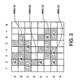
- This divided field map is shown in Fig. 3 .
- each column of the divided field map is related to one of numerals 1 to 8
- each row of the divided field map is related to one of characters A to H.
- a block in the field map is specified by using one of the numerals and one of the characters.
- the block located at the top right of the field map is referred to as block (8A).
- Each area includes at least five blocks, since an area composed of less than five blocks is not enough to express land in the present game. But, in the other games, an area may include any number of blocks.
- each area corresponds to one of the above mentioned four partial scenarios and the dungeon is formed as land.
- the concept of the invention may be applied similarly when the other dungeon patterns are used.
- the selection of the areas are generally done by using random number. But, the areas may also decided based on factors such as a value designated by the user or outside information.
- process uses the random number (or process randomly do 7), it is shown that the different result is obtained when the process is repeated such as by restarting the game or moving to the other scenario.
- the number of blocks of the whole areas or the number of the area may be limited according to characteristics of game.
- the unselected areas represent the sea.
- the selected areas are each divided into two sub areas at step S14. Thereby, in addition to boundaries among the four areas, boundaries between the above two sub areas are generated. According to the invention, more natural geographical features may be generated by locating a mountain or a river along the boundaries of the sub areas.
- some blocks may be selected as additional sub areas from the remaining blocks which are not selected as the four areas and are next to one of the blocks selected as the four area.
- three additional sub areas may be added and each sub area includes one block. The additional sub areas are also generated to realize natural geographical features.
- the areas selected at step S12 are an area a (a0 and a1), an area b (b0 and b1), an area c (c0 and c1), and an area d (d0 and d1).
- the blocks in each parenthesis are sub areas divided at step S14.
- the additional areas added at step S16 are a2, a3, and c2. Consequently, the field map of Fig. 3 includes the area a (a0, a1, a2, and a3), the area b (b0 and b1), the area c (c0, c1, and c2), the area d (d0 and d1).
- step s18 definition is made and appearance of land at each sub area is determined.
- two sub areas are defined so as to include a snowy field
- other two areas are defined so as to include a desert
- the other areas are defined so as to include a grassy plain.
- These definitions are generally generated by using random number, but as described above, the other way may be used.
- the sub areas b0 and b1 includes the snowy field
- the sub areas c0 and c2 includes the desert.
- Fig. 4A three blocks (5A, 5B, and 5C) are shown.
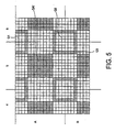
- Fig. 5 shows enlarged blocks near the block 5B in the field map of Fig. 3 and the field map is divided into 128 by 128 cells.
- each quadrilateral formed by dividing the field map into 128 by 128 is referred to as "cell".
- the cell corresponds to pixel of the image on a monitor. Color is defined for each cell, as a whole, an image is displayed on the monitor.
- points "1" are each located at the center of the blocks (denoted by symbols “o") and points "2" are each located near the midpoint of one of the four sides of the blocks (denoted by symbols " ⁇ ").
- Each point “1" " is located at the center of the block, but it is not necessary that the center strictly means the center of gravity. Therefore, the point “1" is located at a location which is determined in a predetermined range near the center by using such as a random number.
- the predetermined range is, for example, shown as 5A' in Fig. 5 which is 8 by 8 cells located at a central portion of the block and denoted as a shaded portion.
- the size of cells is referred to as "sub block”.
- the point "2" is located for each side of each block, but it is not necessary to locate the midpoint of the side.
- a location of the point "2" may be determined in a predetermined range near the midpoint by using such as a random number.
- the range is shown as a sub block Q3 in Fig. 5 , which includes boundaries between blocks.
- middle additional point is given between two points "2" which located at adjacent exterior sides of the blocks forming an area (that is, the seaside).
- the middle additional points are shown (p1 to p4, denoted by symbol " ⁇ ".
- the middle additional points are located in a predetermined range by using a random number.
- the predetermined range is, for example for the middle additional point P2, a sub block Q2 shown in Fig. 5 which covers blocks 5A, 6A, 5B, and 6B and is composed of 8 by 8 cells surrounded by shaded frame.
- the middle additional point P1 is located in a sub block Q1.
- the point P1 is not located at a portion above the row A, since the portion is out of the field map. Therefore, a location of the P1 is determined in a portion where the row A and the sub block Q1 overlap each other by using a random number.
- middle additional points P3 and P4 are determined, as a result, outline of land shown in Fig. 4B (denoted by a bold line) is obtained.
- Resulting field map is obtained by performing the above process on the whole blocks and the field map is shown in Fig. 6 . Since corners and sides of the land of Fig. 6 are randomly changed, it is possible to express more natural seaside. Therefore, comparing with the original areas shown in Fig. 3 , the areas shown in Fig. 6 are expressed in more natural aspect.
- step S24 reads are located between the points.
- the process locate a crossroads by connecting the top point “2" and the bottom point “2” passing through the point "1", and connecting the right point “2” and the left point “2” passing through the point “1".
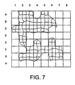
- Fig. 7 the field map including thus located crossroads is shown. It is not necessary that each road is formed as a straight line, and as a shape of the road, any shape including a curve may be selected based on, for example, a random number.
- Each of the roads is assigned as a path where the character of the game walks through, but the road is not always displayed as a path.
- step S24 may be perfonned after step S20 or before step S28 described later. For each cell, information whether or not the cell is assigned as the road is retained.
- step S26 the second transformation is performed.
- the process extends or wears away the field map which is transformed at step S22 (the first transformation).
- the sub block includes 8 by 8 cells and may be categorized into the following three categories (1) to (3).
- Sub block of categories (2) and (3) is further categorized based on whether the surrounding blocks are land or the sea.
- the categorization is explained with reference to Figs. 8A to 8E and 9A to 9D .
- quadrilateral which is denoted by bold line and covers two or four blocks is subjective sub block. Name of the sub block is shown in quotation marks (II).
- the category (2) is still categorized into categories (2-1) to (2-5).
- projected portion such as a cape may be projected only within the predetermined sub block range.
- the top left seaside of the land block can be projected or worn in a range of a sub block which covers four blocks (the sub block belongs to [SEA_SAME]). This is because that the middle additional point pt is randomly located in the sub block.
- the seaside is expanded so as not to connect the other land block.
- process about a sub block [SEA_SAME] is illustrated, basically same process may be performed on e specification description is made about a sub block [SEA_DIFFER].
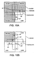
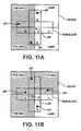
- the sub block [SEA_SAME] is categorized into three patterns as shown in Figs. 10B , 11A, and 11B , according to a combination the number of land blocks and the number of sea blocks.
- a sub block A which covers a sea block and two sub blocks E and B are shown.
- a sub block A which covers two sea blocks, two sub blocks E and D are shown.
- a sub block B which covers a sub block B ([SEA]) are shown.
- a sub block A which covers three sea blocks, two sub blocks C and D are shown.
- each of pt0 and pt1 represents the point "2" used in the first transformation (denoted by “ ⁇ "), and pt4 represents middle additional point used in the first transformation (denoted by " ⁇ ").
- pt4 is connected to pt0 and pt1 to create seaside. Also, pt4 is not used and pt0 and pt1 may be connected each other.
- a new points pt2 and pt3 are added to each example shown in Figs. 10B , 11A, and 11B .
- x-coordinates of the pt0, pt1, and pt4 are averaged and y-coordinates of the pt0, pt1, and pt4 are averaged, and the pt2 is added at the location having averaged x-coordinate and averaged y-coordinate.
- coordinates of pt0, pt1, and pt4 can be represented as (x0, y0), (x1, y1), and (x4, y4), respectively.
- coordinates of pt2 is represented as ((x0 + x1 + x4)/3, (y0 + y1 + y4)/3).
- one of a triangle connecting points pt0, pt2, and pt4 and a triangle connecting points pt1, pt2, and pt4 is selected as land to expand a land portion.
- the both triangles may be selected.
- the selection of triangles may be performed using a random number. Therefore, if only the triangle which connects points pt0, pt2, and pt4 is selected, the seaside is formed along points pt0, pt2, pt4, and pt1. On the other hand, if only the triangle which connects points pt1, pt2, and pt4 is selected, the seaside is formed along points pt0, pt4, pt2, and pt1.
- a point pt2 is randomly located in a sub block B.
- one of a triangle connecting points pt0, pt2, and pt4 and a triangle connecting points pt1, pt2, and pt4 is selected as land to expand a land portion: The both triangles may be selected.
- each of points pt2 and pt3 is randomly located in a sub block B.
- one of a triangle connecting points pt0, pt2, and pt4 and a triangle connecting points pt1, pt3, and pt4 is selected as land to expand a land portion.
- the both triangles may be selected. Therefore, if only the triangle which connects points pt0, pt2, and pt4 is selected, the seaside is formed along points pt0, pt2, pt4, and pt1.
- the seaside is formed along points pt0, pt4, pt3, and pt1. If the both triangles are selected, the seaside is formed along points pt0, pt2, pt4, pt3, and pt1.
- the above mentioned expansion process can transform the seaside more complex to create more natural seaside by projecting the seaside toward the sea.
- the wearing process selects some land cells (cells belong to the land portion) contacting with a sea cell (cell belongs to the sea portion) among sub blocks [SEA_SAME], [SEA_DIFFER], [SEA_SIDE], and [B_SEA], creates line starting from one of the land cells in the land portion with random curve, and changes two cells wide land cells to sea cells along the created line.
- the cell means a quadrilateral which is obtained by dividing the whole field map into 128 by 128 in a lattice form.
- the cell is referred to as "sea cell”
- the cell is referred to as "land cell”.
- a sub block [SEA_SAME] and an adjacent block is shown.
- a sub block includes 8 by 8 cells.
- a sea cell which contacts with a land cell is selected.
- line is extended with randomly curving from a land cell contacting with the selected sea cell toward land.
- the extension of the line is performed by some extension operations.
- the direction and length of each extension operation are determined, for example, by a random number.
- a wearing line is created as shown in Fig. 12 .
- Fig. 12B When the wearing line is created, cells are worn along the line with two cells width. That is, the worn cells (land cells) are changed to sea cells.
- Fig. 12B cells which are changed to sea cells are denoted by x mark.
- a way of treating of two cells width is decided as desired.
- wearing line cells which the wearing line passes through and upper, lower, right, and left adjacent cells of the wearing line cells are changed to sea cells.
- the wearing line can proceed beyond the boundary between the sub blocks, but can not stride the path between the points established at step S24. This is because that the path should be located on land, and for each cell, information whether or not the cell is assigned to the path is managed.
- the wearing process may be further repeated by selecting some starting land cells.
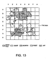
- Fig.13 field map processed by the processes mentioned above is shown.
- the boundary between a land portion and a sea portion, that is seaside, has various and complex undulations to form more natural geographical features comparing with the seaside shown in Fig. 6 .
- the seaside in Fig. 13 is drastically transformed far from the original quadrilateral blocks.
- step S28 land which is processed by the second transformation is decorated.
- the decoration process includes 3D process, scene arrange process, and object arrange process.
- the 3D process adds 3D effect on the field map to express more natural and undulating land.
- the scene arrange process arranges a snowy field and a desert according to setting of each area.
- the object arrange process arranges objects and items required for the game on the field map.
- the scene arrange process arranges forest on a grassy field or a snowy field, and arranges a craggy mountain on a desert.
- the size and location of the forest and the craggy mountain may be determined on the basis of a random number.
- geographical items which prevents a character from pass through such as a mountain, a river, and a lake, are located at the boundaries between areas.
- a bridge should be located, or when a sub block is separated by a mountain, a tunnel is created in the mountain. Also, the bridge and the tunnel are created so as to connects two points "2".
- Example of field map which is obtained by performing these processes is shown in Fig. 13 .
- a shape of land portions is drastically changed, but each of the portions still corresponds to one of the sub area shown in Fig. 3 . Therefore, description is made about each part of the field map using the names of the sub areas.
- Mountains (shown in Fig. 13 as fields shadowed by slanted lines) are located at boundaries between the sub areas b1 and b0, b0 and a0, a0 and a1, c0 and c1, c1 and d0, and d0 and d1. And if the above two sub areas belong to the same area, a tunnel (shown in Fig. 13 as a symbol denoted by two short lines crossing the mountain) is located to pass through the mountain.
- Rivers (the mouths of the rivers are denoted by arrows in Fig. 13 ) are located at boundaries between the sub areas a0 and a1, c0 and c1 and d0 and d1. Since the pairs of the sub areas belong to the same area, bridges (shown in Fig. 13 as symbols denoted by two short lines crossing the rivers) are built so that the game character may passes through the rivers.
- the remaining portions of land are grassy field, and forests (shown in Fig. 13 as fields filled by a plural of dots) are located in some parts of the grassy field. Also, craggy mountains (not shown in Fig. 13 ) are randomly located in desert portions. Furthermore, a lake (shown in Fig. 13 as a field filled by a plurality of x marks) is located in the sub area a0.
- a method which automatically changes information of a field map expressing a dungeon to represent the dungeon in more natural aspect and with more complex geographical features.
Landscapes
- Engineering & Computer Science (AREA)
- Multimedia (AREA)
- Processing Or Creating Images (AREA)
Description
- The invention relates to a method of generating field map automatically in a video game, and in particular, a method of generating more natural geographical features by transforming a selected quadrilateral automatically.
- Nowadays, video game devices have been spread to many families rapidly And there are various games, such as a role-playing game, a simulation game, a combat game, a puzzle game, and the like.
- In the role-playing game, dungeon is often used. In the game, treasure or items which are necessary for the game may be hidden in the dungeon, or a strong monster may appear from the dungeon.
- Herein, the dungeon generally means "labyrinth" in actual game. Therefore, the dungeon may be expressed as land, a natural cave, an ice cave, or a lava cave. In such a game, a video game character (for example, main character) moves in the dungeon and therein, encountering various items and monsters, a story of the game proceeds. Of course, the story varies according to selection of loads or response to encountering items or monsters. In this specification, image data representing whole geographical features which are used as the dungeon are referred to "field map".
- In general, it is necessary to prepare many patterns of shapes of the dungeon (for example, a shape of land) so that a user of the game does not to lose interest in the game. To this end, when the game is started or at the other timing, a shape of the dungeon is automatically generated, for example, by using random number.
- However, in the prior game, a shape of the dungeon which is automatically generated becomes unnatural shape since the dungeon is generated by combining a plurality of quadrilaterals. For example, even if the dungeon expresses land or a cave, a boundary of the dungeon, that is, a boundary line between the land and the sea surrounding the dungeon is not generated in a natural and complex shaped
- In other words, the boundary line is formed as a shape of steps, that is, a shape with coarse notches in the prior game. Due to the limitation of expression, natural and complex geographical features are not fully represented. Therefore, when a story of the game proceeds on a nature, it is not possible to communicate to a user of the game a feeling of open-air or refreshment, as a result, it is not possible to give the user a feeling of being at a live performance.
-
US-A-5 417 425 discloses a puzzle device which includes an array of indicators, each of the indicators being capable of alternately indicating a first state or a second state, means for selecting one of the array of indicators, and means for changing, upon the selection of one of the array of indicators, the state of at least one of the other of the indicators based on a predetermined pattern. - It is an object of the invention to provide a method of representing dungeon in more natural shape. To this end, the method transforms a part of field map representing the dungeon to generate more natural shape of dungeon. This object is solved by the features of the claims.
-
Fig. 1 shows a block diagram of a video game device according to an embodiment of the invention; -
Fig. 2 shows a flowchart representing a method according to an embodiment of the invention; -
Fig. 3 shows field map, including eight by eight blocks, in which an area is selected; -
Figs. 4A and 4B show diagrams schematically representing a first transforming process; -
Fig. 5 shows a diagram representing a part of the field map which is divided into 128 by 128 cells; -
Fig. 6 shows a diagram of field map which is processed by the first transforming process; -
Fig. 7 shows a diagram of field map after a path is added to the field map ofFig. 6 ; -
Figs. 8A-8E show diagrams representing child blocks each of which stretches over four blocks; -
Figs. 9A - 9D show diagrams representing child blocks each of which stretches over two blocks; -
Figs. 10A and 10B show diagrams representing patterns of extension process; -
Figs. 11A and 11B show diagrams representing other patterns of extension process; -
Figs. 12A and 12B show diagrams representing procedure of wearing process; and -
Fig. 13 shows an example of finally obtained field map. - Referring to
Fig. 1 , description is at first made about a video game device of an embodiment of the invention. The video game device shown inFig. 1 is merely exemplified and may be changed to any other game devices or machines. - The
video game device 100 shown inFig. 1 includes abody 100, atelevision monitor 130, aspeaker 140, arecording medium 150, amemory card 160, and acontroller 170. Theelements 130 through 170 are connected to thebody 100. The game device is suited for home use. - The
body 100 further includes aCPU 111, abus 112 connected to theCPU 111, and some elements connected to thebus 112. - The
bus 112 includes an address bus, a data bus, and a control bus. A graphicdata generating processor 113, aperipheral device controller 114, amain memory 115, aROM 116, anexpansion circuit 117, agraphic processor 118, aframe buffer 119, asound processor 120, asound buffer 121, adecoder 123, abuffer 122, arecording medium drive 124, and aninterface circuit 125. - The television monitor 130(hereinafter, referred to as a "monitor") is connected to the
graphic processor 118. Further, thespeaker 140 is connected to thesound processor 120, and thememory card 160 and thecontroller 170 are connected to theinterface circuit 125. - As mentioned above, the video game device shown in
Fig. 1 is an example suited for home use. In this case, it is general that the monitor of a home television is used as themonitor 130 and a speaker of the home television is used as thespeaker 140. - In the case where the method according to the invention is applied to the arcade game device, the above mentioned elements shown in
Fig. 1 may be all incorporated into a single body. - Also, when the method of the invention is used in a personal computer of a workstation, a CRT display connected to the personal computer may be used as the
monitor 10, and an input device such as a keyboard or a mouse is used as thecontroller 20. - Then, description is made about the game device in more detail.
- The
CPU 111 is, for example, a 32-bits RISC (reduced instruction set computer), and controls all elements of the game device by executing an operating system program stored in aROM 116, which is described later. - The graphic
data generating processor 113 serves as a co-processor of theCPU 111. That is, theprocessor 113 executes calculation for coordinate transformation and a light source, for example, operation of fixed decimal or vector, with parallel processing to display a pseudo three-dimensional image. - The
peripheral device controller 114 executes control operation for interruption, time, memory, and direct memory access (DMA) transfer. TheROM 116 stores, as described above, the operating system program which controls operations of the elements in the game device. - The
expansion circuit 117 decodes still or animated image data read out from therecording medium 150 and stored in themain memory 115, under the control of theaforementioned CPU 111, and stores the decoded image data back in themain memory 115. Specifically theexpansion circuit 117 is capable of carrying out high-speed execution of inverse discrete cosine transform (inverse DCT) operations, and it is also capable of expanding compressed data read out from therecording medium 150 in accordance with still color image compression standards (known as JPEG) or cumulative media moving image encoding standards (known as MPEG). - Field map is generated according to the method of transforming field map of the invention, and the field map is stored into the
frame buffer 119. Consequently, the field map is displayed on themonitor 130. The above process is cooperatively executed by theCPU 111, the graphicdata generating processor 113, thegraphic processor 118, and theframe buffer 119. Description about the process will be made later in more detail. - The
frame buffer 119 includes a display area and a non-display area. The display area is an area for storing images corresponding to a display area on themonitor 130. The non-display area is an area for storing animation images used to produce two-dimensional images in the display area and textures used to produce pseudo three-dimensional images. - In some case, the
frame buffer 119 includes a color lookup table (CLUT) which corresponds to a color of pixel to a number. Also, data in the display area in theframe buffer 119 are transferred to themonitor 130 at high-speed. Theframe buffer 119 consists of a so-called dual-port RAM, and it is capable of simultaneously receiving images from the graphic data generating processor 113 (CPU 111) or transferring data from themain memory 115, and reading out data in order that the data can be displayed to themonitor 130. - The
sound processor 120 outputs music or an effective sound viaspeaker 140 by regenerating ADPCM data in therecording medium 150 or voice data stored in thesound buffer 121, or by modulating and regenerating the voice data. - The
decoder 123 decodes a program or data which are stored in therecording medium 150 and are appended an error correction code (ECC), and provides the program or the data to themain memory 115 or thesound processor 120. - The
buffer 122 temporarily stores the program and/or data regenerated from therecording medium 150. Thebuffer 122 has a memory capacity of, for example, 32 kilobytes. - The
recording medium drive 124 may be a CD-ROM drive, an optical disk drive, or the like. Therecording medium drive 124 reads a program and another data out of therecording medium 150, and provides them to thedecoder 123. - The
interface circuit 125 sends an operation signal received from thecontroller 170 to theCPU 111. Also, theinterface circuit 125 reads out the contents of thememory card 160 to supply the contents to themain memory 115, and simultaneously stores data into thememory card 160 in response to an instruction of theCPU 111. - A
recording medium 150 stores a program and image data required to play a game. The program and the image data are read from therecording medium 150 to a video game device via therecording medium drive 124. The recording medium itself is, for example, a CD-ROM or an optical disk. - The
memory card 160 stores values of a various of parameters in order to, for example, maintain the status at the time point when a game terminates last time. The values are transferred to thememory card 160 via theinterface circuit 125 as required. To this end, thememory card 160 is connected to a slot of theinterface circuit 125. - A handy-type video game device is also connected to a slot of the front side of the
interface circuit 125, and a program and data of the video game of thebody 100, required to play a game are transferred to the handy-type video game device. - The
controller 170 is manipulated to play a game by a user. Thecontroller 170 includes direction buttons for moving a character on the monitor upwards, downwards, leftwards and rightwards, and a plurality of function buttons for instructing one of specific functions, for example, starting the game or selecting items. - The method of transforming field map of the invention may be used in, for example, the following RPG game.
- In the RPG game, four partial scenarios are selected from a first partial scenario through a tenth partial scenario, and the selected partial scenarios are combined as a first stage through a fourth stage to generate a story of the game.
- According to a condition of ending of the first stage partial scenario, the second stage partial scenario is dynamically selected. Herein, the condition of ending of the first stage partial scenario and a condition of starting of the second stage partial scenario are related so that a transition of two partial scenario is naturally done as a story.
- Specifically, the first stage partial scenario is selected from the first partial scenario through the eighth partial scenario, and the condition of ending of the first stage partial scenario is prepared according to a result of processing in the scenario. Therefore, one of the first partial scenario through the tenth partial scenario may be selected as the second stage partial scenario. Thereafter, similar selections are done about the third stage partial scenario and the fourth stage partial scenario.
- In the RPG game, scene (area) is changed for each partial scenario, thereby a user of the game newly interests in the game. For example, a first island, a second island, a third island, and a fourth island (a first area through a fourth area) which are defined on a field map corresponds to the first stage partial scenario, the second stage partial scenario, the third stage partial scenario, and the fourth stage partial scenario, respectively, and at the end of the first stage partial scenario, a scene displaying the first island is changed to another scene displaying the second island.
- The change of the scene is a part of the game (story), for example, if the condition of ending of the first stage partial scenario is meet, the second island is displayed, and a bridge is created or a ferry is provided so that the main character may move from the first island to the second island.
- As described above, the appearance and the change of these scene are important element for the game. Therefore, if the scene (area) includes natural geographical features, such as islands or land, natural expression of the scene (area) is required so that the user may feel open-air or refreshment sense, and atmosphere of being at a live performance.
- Next, description is made about transform process of a field map according to the invention with reference to
Figs. 2 through 13 . - In
Fig. 2 , a flowchart of the transform process is shown. At step S10, the field map is divided into 64 (8 by 8) quadrilateral blocks. This divided field map is shown inFig. 3 . Herein, for designating each block later, each column of the divided field map is related to one ofnumerals 1 to 8, and each row of the divided field map is related to one of characters A to H. Thereby, a block in the field map is specified by using one of the numerals and one of the characters. For example, the block located at the top right of the field map is referred to as block (8A). - At step S12, four areas to which land is assigned are selected. Each area includes at least five blocks, since an area composed of less than five blocks is not enough to express land in the present game. But, in the other games, an area may include any number of blocks.
- In this example, each area corresponds to one of the above mentioned four partial scenarios and the dungeon is formed as land. The concept of the invention may be applied similarly when the other dungeon patterns are used.
- The selection of the areas are generally done by using random number. But, the areas may also decided based on factors such as a value designated by the user or outside information. Hereinafter, when process uses the random number (or process randomly do ...), it is shown that the different result is obtained when the process is repeated such as by restarting the game or moving to the other scenario.
- For example, when the game is restarted, other four areas forms different shape of land.
- Also, the number of blocks of the whole areas or the number of the area may be limited according to characteristics of game. Herein, the unselected areas represent the sea.
- Thereafter, the selected areas are each divided into two sub areas at step S14. Thereby, in addition to boundaries among the four areas, boundaries between the above two sub areas are generated. According to the invention, more natural geographical features may be generated by locating a mountain or a river along the boundaries of the sub areas.
- Further, at step S16, some blocks may be selected as additional sub areas from the remaining blocks which are not selected as the four areas and are next to one of the blocks selected as the four area. Herein, three additional sub areas may be added and each sub area includes one block. The additional sub areas are also generated to realize natural geographical features.
- Thus selected areas are also shown in
Fig. 3 . The areas selected at step S12 are an area a (a0 and a1), an area b (b0 and b1), an area c (c0 and c1), and an area d (d0 and d1). Herein, the blocks in each parenthesis are sub areas divided at step S14. The additional areas added at step S16 are a2, a3, and c2. Consequently, the field map ofFig. 3 includes the area a (a0, a1, a2, and a3), the area b (b0 and b1), the area c (c0, c1, and c2), the area d (d0 and d1). - Next, at step s18, definition is made and appearance of land at each sub area is determined. In this example, two sub areas are defined so as to include a snowy field, other two areas are defined so as to include a desert, and the other areas are defined so as to include a grassy plain. These definitions are generally generated by using random number, but as described above, the other way may be used. Specifically, the sub areas b0 and b1 includes the snowy field and the sub areas c0 and c2 includes the desert.
- Then, for each selected block, five points are given at step S20. These points are places where a town, a harbor, a cave, or a tower are located.
- Description is made about the establishment of the points with reference to
Fig. 4 and5 . - In
Fig. 4A , three blocks (5A, 5B, and 5C) are shown. On the other hand,Fig. 5 shows enlarged blocks near theblock 5B in the field map ofFig. 3 and the field map is divided into 128 by 128 cells. - In
Fig. 3 , one quadrilateral corresponds to one block, but inFig. 5 , 16 by 16 cells (quadrilaterals) correspond to one block. Herein, each quadrilateral formed by dividing the field map into 128 by 128 is referred to as "cell". The cell corresponds to pixel of the image on a monitor. Color is defined for each cell, as a whole, an image is displayed on the monitor. - Referring to
Fig. 4A again, points "1" are each located at the center of the blocks (denoted by symbols "ⓞ") and points "2" are each located near the midpoint of one of the four sides of the blocks (denoted by symbols "●"). - Each point "1" " is located at the center of the block, but it is not necessary that the center strictly means the center of gravity. Therefore, the point "1" is located at a location which is determined in a predetermined range near the center by using such as a random number. The predetermined range is, for example, shown as 5A' in
Fig. 5 which is 8 by 8 cells located at a central portion of the block and denoted as a shaded portion. Hereinafter, the size of cells is referred to as "sub block". - On the other hand, the point "2" is located for each side of each block, but it is not necessary to locate the midpoint of the side. A location of the point "2" may be determined in a predetermined range near the midpoint by using such as a random number. The range is shown as a sub block Q3 in
Fig. 5 , which includes boundaries between blocks. - Four points "2" are given for each block, but when there are blocks sharing a side with the other block, the point "2" is also shared. For example, in
Fig 4A , theblock 6B and theblock 5B share a point "2", and theblock 5A and block 5B share a point "2". - Next, at step S22, transformation process is performed using the points "2". Referring to
Fig. 4A , at first, middle additional point is given between two points "2" which located at adjacent exterior sides of the blocks forming an area (that is, the seaside). InFig. 4A , in addition to the points "1" and the points "2", the middle additional points are shown (p1 to p4, denoted by symbol "▲". The middle additional points are located in a predetermined range by using a random number. The predetermined range is, for example for the middle additional point P2, a sub block Q2 shown inFig. 5 which coversblocks Fig. 4B (denoted by a bold line) is obtained. - Resulting field map is obtained by performing the above process on the whole blocks and the field map is shown in
Fig. 6 . Since corners and sides of the land ofFig. 6 are randomly changed, it is possible to express more natural seaside. Therefore, comparing with the original areas shown inFig. 3 , the areas shown inFig. 6 are expressed in more natural aspect. - By moving each apex of the area in a predetermined range, it is possible to change the prior unnatural boundary line which is formed as a shape of steps to more natural boundary line, to express more complex seaside. Further, the transformed boundary line is transformed so as to express a shape closer to a natural shape. This second transformation is described later in more detail.
- Referring to flowchart of
Fig. 2 again, in step S24, reads are located between the points. The process locate a crossroads by connecting the top point "2" and the bottom point "2" passing through the point "1", and connecting the right point "2" and the left point "2" passing through the point "1". InFig. 7 , the field map including thus located crossroads is shown. It is not necessary that each road is formed as a straight line, and as a shape of the road, any shape including a curve may be selected based on, for example, a random number. Each of the roads is assigned as a path where the character of the game walks through, but the road is not always displayed as a path. The road is sometime displayed, as if the road does not exist, for example, as a grass field or a forest. Also, step S24 may be perfonned after step S20 or before step S28 described later. For each cell, information whether or not the cell is assigned as the road is retained. - Next, in step S26, the second transformation is performed. The process extends or wears away the field map which is transformed at step S22 (the first transformation).
- Description is made about the second transformation with reference to the sub blocks shown in
Fig. 5 . The sub block includes 8 by 8 cells and may be categorized into the following three categories (1) to (3). - (1) Sub block located at the center of a block (5A' in
Fig. 5 ). - (2) Sub block located to cover four blocks (Q1 and Q2 in
Fig. 5 ). - (3) Sub block located to cover two blocks (Q3 in
Fig. 5 ). - Sub block of categories (2) and (3) is further categorized based on whether the surrounding blocks are land or the sea. The categorization is explained with reference to
Figs. 8A to 8E and9A to 9D . Herein, quadrilateral which is denoted by bold line and covers two or four blocks is subjective sub block. Name of the sub block is shown in quotation marks (II). - Next, description is made about the further categorization of the category (2). The category (2) is still categorized into categories (2-1) to (2-5).
- (2-1) At least one of the surrounding blocks is the sea and the rest are land of the same area ([SEA_SAME]). The sub block of the case is shown in
Fig. 8A . At most, three sea blocks may exist. - (2-2) At least one of the surrounding blocks is the sea and the rest are land ([SEA-DIFFER]). Further, land of one of the land blocks belongs to different area of land of another land block. The sub block of the case is shown in
Fig. 8B . In this case, at most, two sea blocks may exist - (2-3) All of the surrounding blocks are land of the same area ([SAME]). The sub block of the case is shown in
Fig. 8C . - (2-4) All of the surrounding blocks are land and land of one of the blocks belongs to different area of land of another land block ([DIFFER]). The sub block of the case is shown in
Fig. 8D . - (2-5) All of the surrounding blocks are the sea ([SEA]). The sub block of the case is shown in
Fig. 8E . - (3-1) Sub block covers a sea block and a land block ([SEA_SIDE]). The sub block in the case is shown in
Fig. 9A . - (3-2) A land block is separated from another land block of another area by the sea ([B_SEA]). The sub block in the case is shown in
Fig. 9B . As described above, one area is normally separated from the other areas and when user of the game finishes (dears) a partial scenario, the areas are connected (or means of the connection is given). In this case, the sea separates one area from the other are. - (3-3) A land block is separated from another land block of another area by a mountain ([HIMT]). The sub block in the case is also shown in
Fig. 9B . The areas are separated because of the same reason as the above category (3-2). - (3-4) A land block is separate from another land block of another area by a river ([B_RIVER]). The sub block in the case is shown in
Fig. 9B . The areas are separated because of the same reason as the above category (3-2). - (3-5) Sub block covers land blocks of the same area ([B_INT]). The sub block in the case is shown in
Fig. 9C . - (3-6) Sub block covers sea blocks ([SEA]). The sub block in the case is shown in
Fig. 9D . - Description is made about the process with reference to
Figs. 10 and11 . As described aboutFig. 5 , projected portion such as a cape may be projected only within the predetermined sub block range. For example, inFig. 10A , the top left seaside of the land block can be projected or worn in a range of a sub block which covers four blocks (the sub block belongs to [SEA_SAME]). This is because that the middle additional point pt is randomly located in the sub block. - Herein, to create more complex geographical features to express more natural seaside, the seaside is expanded so as not to connect the other land block. In this example, process about a sub block [SEA_SAME] is illustrated, basically same process may be performed on e specification description is made about a sub block [SEA_DIFFER].
- The sub block [SEA_SAME] is categorized into three patterns as shown in
Figs. 10B ,11A, and 11B , according to a combination the number of land blocks and the number of sea blocks. - In
Fig. 10B , a sub block A which covers a sea block and two sub blocks E and B ([SEA_SIDE]) are shown. InFig. 11A , a sub block A which covers two sea blocks, two sub blocks E and D ([SEA_SIDE]), and a sub block B ([SEA]) are shown. InFig. 10C , a sub block A which covers three sea blocks, two sub blocks C and D ([SEA_SIDE]), and two sub blocks B and E ([SEA]) are shown. - In
Figs. 10B ,11A, and 11B , each of pt0 and pt1 represents the point "2" used in the first transformation (denoted by "●"), and pt4 represents middle additional point used in the first transformation (denoted by "▲"). In the first transformation, pt4 is connected to pt0 and pt1 to create seaside. Also, pt4 is not used and pt0 and pt1 may be connected each other. - Herein, a new points pt2 and pt3 are added to each example shown in
Figs. 10B ,11A, and 11B . InFig. 10B , x-coordinates of the pt0, pt1, and pt4 are averaged and y-coordinates of the pt0, pt1, and pt4 are averaged, and the pt2 is added at the location having averaged x-coordinate and averaged y-coordinate. Therefore, if when x-coordinate and y-coordinate of a point ptn can be represented as (Xn, Yn) on the basis of an arbitrary point on the field map, coordinates of pt0, pt1, and pt4 can be represented as (x0, y0), (x1, y1), and (x4, y4), respectively. Further, coordinates of pt2 is represented as ((x0 + x1 + x4)/3, (y0 + y1 + y4)/3). - Herein, one of a triangle connecting points pt0, pt2, and pt4 and a triangle connecting points pt1, pt2, and pt4 is selected as land to expand a land portion. The both triangles may be selected. The selection of triangles may be performed using a random number. Therefore, if only the triangle which connects points pt0, pt2, and pt4 is selected, the seaside is formed along points pt0, pt2, pt4, and pt1. On the other hand, if only the triangle which connects points pt1, pt2, and pt4 is selected, the seaside is formed along points pt0, pt4, pt2, and pt1.
- In
Fig. 11A , a point pt2 is randomly located in a sub block B. Herein, one of a triangle connecting points pt0, pt2, and pt4 and a triangle connecting points pt1, pt2, and pt4 is selected as land to expand a land portion: The both triangles may be selected. - In
Fig. 11B , each of points pt2 and pt3 is randomly located in a sub block B. Herein, one of a triangle connecting points pt0, pt2, and pt4 and a triangle connecting points pt1, pt3, and pt4 is selected as land to expand a land portion. The both triangles may be selected. Therefore, if only the triangle which connects points pt0, pt2, and pt4 is selected, the seaside is formed along points pt0, pt2, pt4, and pt1. On the other hand, if only the triangle which connects points pt1, pt3, and pt4 is selected, the seaside is formed along points pt0, pt4, pt3, and pt1. If the both triangles are selected, the seaside is formed along points pt0, pt2, pt4, pt3, and pt1. - The above mentioned expansion process can transform the seaside more complex to create more natural seaside by projecting the seaside toward the sea.
- The wearing process selects some land cells (cells belong to the land portion) contacting with a sea cell (cell belongs to the sea portion) among sub blocks [SEA_SAME], [SEA_DIFFER], [SEA_SIDE], and [B_SEA], creates line starting from one of the land cells in the land portion with random curve, and changes two cells wide land cells to sea cells along the created line. As described above, the cell means a quadrilateral which is obtained by dividing the whole field map into 128 by 128 in a lattice form. When the cell is assigned to the sea, the cell is referred to as "sea cell", when the cell is assigned to land, the cell is referred to as "land cell".
- In this example, description is made about a sub block [SEA_SAME] with reference to
Fig. 12 , other blocks [SEA_DIFFER], [SEA_SIDE], and [B_SEA] may be processed in a similar manner. - In
Fig. 12A , a sub block [SEA_SAME] and an adjacent block is shown. As described above, a sub block includes 8 by 8 cells. At first, a sea cell which contacts with a land cell is selected. Then, line is extended with randomly curving from a land cell contacting with the selected sea cell toward land. The extension of the line is performed by some extension operations. The direction and length of each extension operation are determined, for example, by a random number. After repeating the extension operations, a wearing line is created as shown inFig. 12 . - When the wearing line is created, cells are worn along the line with two cells width. That is, the worn cells (land cells) are changed to sea cells. The operation is shown in
Fig. 12B . Herein, cells which are changed to sea cells are denoted by x mark. Also, a way of treating of two cells width is decided as desired. For example, inFig. 12B , wearing line cells which the wearing line passes through and upper, lower, right, and left adjacent cells of the wearing line cells are changed to sea cells. As shown inFig. 12B , the wearing line can proceed beyond the boundary between the sub blocks, but can not stride the path between the points established at step S24. This is because that the path should be located on land, and for each cell, information whether or not the cell is assigned to the path is managed. - Also, it is possible to give a various limitation of location where the wearing line is expanded to (that is, length of the wearing line). The wearing process may be further repeated by selecting some starting land cells.
- In
Fig.13 , field map processed by the processes mentioned above is shown. The boundary between a land portion and a sea portion, that is seaside, has various and complex undulations to form more natural geographical features comparing with the seaside shown inFig. 6 . Also, the seaside inFig. 13 is drastically transformed far from the original quadrilateral blocks. - Returning to flowchart in
Fig. 2 , in step S28, land which is processed by the second transformation is decorated. The decoration process includes 3D process, scene arrange process, and object arrange process. - The 3D process adds 3D effect on the field map to express more natural and undulating land. The scene arrange process arranges a snowy field and a desert according to setting of each area. The object arrange process arranges objects and items required for the game on the field map.
- These processes are previously or dynamically (with an advance of the game) performed. Furthermore, the scene arrange process arranges forest on a grassy field or a snowy field, and arranges a craggy mountain on a desert. The size and location of the forest and the craggy mountain may be determined on the basis of a random number. In this example, since it is necessary that the areas are conceptually separated each other because of configuration of the game, geographical items which prevents a character from pass through, such as a mountain, a river, and a lake, are located at the boundaries between areas.
- Furthermore, since it should be possible to move all the blocks in an area, for example when a sub block is isolated by the sea or a river, a bridge should be located, or when a sub block is separated by a mountain, a tunnel is created in the mountain. Also, the bridge and the tunnel are created so as to connects two points "2".
- Example of field map which is obtained by performing these processes is shown in
Fig. 13 . A shape of land portions is drastically changed, but each of the portions still corresponds to one of the sub area shown inFig. 3 . Therefore, description is made about each part of the field map using the names of the sub areas. - In the example shown in
Fig. 13 , since sub areas b0 and a0 are assigned to showy field and sub areas c0 and c2 are assigned to desert, snowy field (shown inFig. 13 as a field shadowed by vertical lines) is shown in the sub areas b0 and a0, and desert (shown inFig. 13 as a field shadowed by horizontal lines) is shown in the sub areas c0 and c2. - Mountains (shown in
Fig. 13 as fields shadowed by slanted lines) are located at boundaries between the sub areas b1 and b0, b0 and a0, a0 and a1, c0 and c1, c1 and d0, and d0 and d1. And if the above two sub areas belong to the same area, a tunnel (shown inFig. 13 as a symbol denoted by two short lines crossing the mountain) is located to pass through the mountain. - Rivers (the mouths of the rivers are denoted by arrows in
Fig. 13 ) are located at boundaries between the sub areas a0 and a1, c0 and c1 and d0 and d1. Since the pairs of the sub areas belong to the same area, bridges (shown inFig. 13 as symbols denoted by two short lines crossing the rivers) are built so that the game character may passes through the rivers. - Three pairs of sub areas a2 and a0, a1 and a3, and c2 and c0 are each separated by the sea, since one of the pair is island. But, since the pairs are each belong to the same area, bridges (shown in
Fig.13 as symbols denoted by two short lines crossing the sea) are built so that the game character may passes through the sea - The remaining portions of land are grassy field, and forests (shown in
Fig. 13 as fields filled by a plural of dots) are located in some parts of the grassy field. Also, craggy mountains (not shown inFig. 13 ) are randomly located in desert portions. Furthermore, a lake (shown inFig. 13 as a field filled by a plurality of x marks) is located in the sub area a0. - In the real game, thus generated field map is displayed as a bird's-eye view, or partly enlarged and displayed in a three-dimensional way as a stage of the game using information of the field map.
- Explanation has been made about the illustrative field map, but it is obvious that the transformation process of the invention can be applied to a various field maps. Further, detail settings of the invention are not limited to the above example, and may be optionally selected. The settings include, for example, the number of blocks, the number of cells, the number of areas, assigning of a sub area, and an arranging way of a snowy field.
- According to the invention, a method is provided which automatically changes information of a field map expressing a dungeon to represent the dungeon in more natural aspect and with more complex geographical features.
The category (3) is still categorized into categories (3-1) to (3-6).
Claims (10)
- A method of generating a two-dimensional field map for use in a video game and drawn on a scene divided into a predetermined number of blocks, each of which is composed of a prescribed number of cells, the method comprising the steps of:defining the blocks into first or second zones with boundaries that are interposed between them and that are stepwise determined by contours of the blocks;locating a plurality of sub-blocks on the boundaries between the first and second zones, each sub-block being smaller than each block and being placed over the boundary or corners of each block; anddeforming the boundaries of the blocks;the deforming step comprising the steps of:determining a point within the sub-block placed over the boundary of two blocks;determining an additional point along the sub-block placed over the corner of the blocks; andconnecting the point and the additional point to deform the boundaries determined by stepwise contours of the blocks and to obtain, as a two-dimensional field map, a deformed two-dimensional field map which has boundaries determined by the point and the additional point.
- The method of claim 1, further comprising:selecting the sub-block from the deformed field map;determining a subsidiary point within the selected sub-block; andconnecting the subsidiary point, the point, and the additional point to further deform the contour of the deformed field map to obtain the field map.
- The method of claim 1 or 2, wherein each of the point, the additional point and the subsidiary point within each sub-block is determined by a random number.
- A video game system (100) which generates a two-dimensional field map for use in a video game and drawn on a scene divided into a predetermined number of blocks, each of which is composed of a prescribed number of cells, the system comprising:defining means for defining the blocks into first or second zones with boundaries that are interposed between them and that are stepwise determined by contours of the blocks;locating means for locating a plurality of sub-blocks on the boundaries between the first and second zones, each sub-block being smaller than each block and being placed over the boundary or corners of each block; anddeforming means for deforming the boundaries of the blocks;the deforming means comprising:determining means for determining a point within the sub-block placed over the boundary of two blocks;determining means for determining an additional point along the sub-block placed over the corner of the blocks; andfirst deforming means for connecting the point and the additional point to deform the boundaries determined by stepwise contours of the blocks and to obtain, as a two-dimensional field map, a deformed two-dimensional field map which has boundaries determined by the point and the additional point.
- The system of claim 4, further comprising:selecting means for selecting the sub-block from the deformed field map;determining means for determining a subsidiary point within the selected sub-block; andsecond deforming means for connecting the subsidiary point, the point, and the additional point to further deform the contour of the deformed field map to obtain the field map.
- The system of claim 4 or 5, wherein each of the point, the additional point and the subsidiary point within each sub-block is determined by a random number.
- A recording medium (150) readable by a computer and making the computer execute a program of generating a two-dimensional field map for use in a video game and drawn on a scene divided into a predetermined number of blocks, each of which is composed of a prescribed number of cells, the program making the computer execute the steps of:defining the blocks into first or second zones with boundaries that are interposed between them and that are stepwise determined by contours of the blocks;locating a plurality of sub-blocks on the boundaries between the first and second zones, each sub-block being smaller than each block and being placed over the boundary or corners of each block; anddeforming the boundaries of the blocks;the deforming step comprising the steps of:determining a point within the sub-block placed over the boundary of two blocks;determining an additional point along the sub-block placed over the corner of the blocks; andconnecting the point and the additional point to deform the boundaries determined by stepwise contours of the blocks and to obtain, as a two-dimensional field map, a deformed two-dimensional field map which has boundaries determined by the point and the additional point.
- The recording medium of claim 7, the program making the computer execute the further steps of:selecting the sub-block from the deformed field map;determining a subsidiary point within the selected sub-block; andconnecting the subsidiary point, the point, and the additional point to further deform the contour of the deformed field map to obtain the field map.
- The recording medium of claim 7 or 8, wherein each of the point, the additional point and the subsidiary point within each sub-block is determined by a random number.
- The method, system or recording medium of any one of the preceding claims, wherein the first zones represent lands and the second zones represent seas, the blocks being defined as lands and seas.
Applications Claiming Priority (2)
| Application Number | Priority Date | Filing Date | Title |
|---|---|---|---|
| JP28070699A JP3270928B2 (en) | 1999-09-30 | 1999-09-30 | Field map generation method, video game system, and recording medium |
| JP28070699 | 1999-09-30 |
Publications (3)
| Publication Number | Publication Date |
|---|---|
| EP1088573A2 EP1088573A2 (en) | 2001-04-04 |
| EP1088573A3 EP1088573A3 (en) | 2001-08-16 |
| EP1088573B1 true EP1088573B1 (en) | 2008-12-17 |
Family
ID=17628826
Family Applications (1)
| Application Number | Title | Priority Date | Filing Date |
|---|---|---|---|
| EP00121226A Expired - Lifetime EP1088573B1 (en) | 1999-09-30 | 2000-09-29 | Method and a video game system of generating a field map |
Country Status (4)
| Country | Link |
|---|---|
| US (1) | US6319129B1 (en) |
| EP (1) | EP1088573B1 (en) |
| JP (1) | JP3270928B2 (en) |
| DE (1) | DE60041107D1 (en) |
Cited By (1)
| Publication number | Priority date | Publication date | Assignee | Title |
|---|---|---|---|---|
| CN105492091A (en) * | 2013-09-18 | 2016-04-13 | 喀普康有限公司 | Game device, game device control method, and recording medium |
Families Citing this family (42)
| Publication number | Priority date | Publication date | Assignee | Title |
|---|---|---|---|---|
| JP2001252464A (en) * | 2000-03-10 | 2001-09-18 | Konami Co Ltd | Game device, game control method, storage medium and program |
| US20020113797A1 (en) * | 2000-11-17 | 2002-08-22 | Potter Scott T. | Systems and methods for representing and displaying graphics |
| AU2002342040A1 (en) | 2001-10-10 | 2003-04-22 | Sony Computer Entertainment America Inc. | Dynamically loaded game software for smooth play. |
| US6907579B2 (en) * | 2001-10-30 | 2005-06-14 | Hewlett-Packard Development Company, L.P. | User interface and method for interacting with a three-dimensional graphical environment |
| KR20030061210A (en) * | 2002-01-11 | 2003-07-18 | (주)픽셀소프트 | Method for automatically generating map data used in a computer game |
| US8133115B2 (en) | 2003-10-22 | 2012-03-13 | Sony Computer Entertainment America Llc | System and method for recording and displaying a graphical path in a video game |
| US20060071933A1 (en) | 2004-10-06 | 2006-04-06 | Sony Computer Entertainment Inc. | Application binary interface for multi-pass shaders |
| CN100388194C (en) * | 2005-04-09 | 2008-05-14 | 华为技术有限公司 | A mobile game client program control method |
| US7636126B2 (en) | 2005-06-22 | 2009-12-22 | Sony Computer Entertainment Inc. | Delay matching in audio/video systems |
| US7459624B2 (en) | 2006-03-29 | 2008-12-02 | Harmonix Music Systems, Inc. | Game controller simulating a musical instrument |
| US7880746B2 (en) | 2006-05-04 | 2011-02-01 | Sony Computer Entertainment Inc. | Bandwidth management through lighting control of a user environment via a display device |
| US7965859B2 (en) | 2006-05-04 | 2011-06-21 | Sony Computer Entertainment Inc. | Lighting control of a user environment via a display device |
| CN100421119C (en) * | 2006-07-11 | 2008-09-24 | 北京金山软件有限公司 | Method for drawing map in game |
| US8678896B2 (en) | 2007-06-14 | 2014-03-25 | Harmonix Music Systems, Inc. | Systems and methods for asynchronous band interaction in a rhythm action game |
| US20090075711A1 (en) | 2007-06-14 | 2009-03-19 | Eric Brosius | Systems and methods for providing a vocal experience for a player of a rhythm action game |
| WO2010006054A1 (en) | 2008-07-08 | 2010-01-14 | Harmonix Music Systems, Inc. | Systems and methods for simulating a rock and band experience |
| US8465366B2 (en) | 2009-05-29 | 2013-06-18 | Harmonix Music Systems, Inc. | Biasing a musical performance input to a part |
| US8449360B2 (en) | 2009-05-29 | 2013-05-28 | Harmonix Music Systems, Inc. | Displaying song lyrics and vocal cues |
| KR100953131B1 (en) * | 2009-09-29 | 2010-04-16 | (주) 골프존 | Apparatus for virtual golf simulation and method for the same |
| WO2011056657A2 (en) | 2009-10-27 | 2011-05-12 | Harmonix Music Systems, Inc. | Gesture-based user interface |
| US9981193B2 (en) | 2009-10-27 | 2018-05-29 | Harmonix Music Systems, Inc. | Movement based recognition and evaluation |
| US8550908B2 (en) | 2010-03-16 | 2013-10-08 | Harmonix Music Systems, Inc. | Simulating musical instruments |
| US10786736B2 (en) | 2010-05-11 | 2020-09-29 | Sony Interactive Entertainment LLC | Placement of user information in a game space |
| WO2011155958A1 (en) | 2010-06-11 | 2011-12-15 | Harmonix Music Systems, Inc. | Dance game and tutorial |
| US8562403B2 (en) | 2010-06-11 | 2013-10-22 | Harmonix Music Systems, Inc. | Prompting a player of a dance game |
| US9358456B1 (en) | 2010-06-11 | 2016-06-07 | Harmonix Music Systems, Inc. | Dance competition game |
| US9024166B2 (en) | 2010-09-09 | 2015-05-05 | Harmonix Music Systems, Inc. | Preventing subtractive track separation |
| US9342817B2 (en) | 2011-07-07 | 2016-05-17 | Sony Interactive Entertainment LLC | Auto-creating groups for sharing photos |
| JP5307923B1 (en) * | 2012-08-20 | 2013-10-02 | 株式会社gloops | GAME SERVER, GAME CONTROL METHOD, PROGRAM, AND GAME SYSTEM |
| US9336618B1 (en) | 2012-11-02 | 2016-05-10 | Kabam, Inc. | Stochastic chunk-based map generation |
| US10186061B1 (en) | 2013-01-11 | 2019-01-22 | Electronic Arts Inc. | Proximate-tile-type-based map generation |
| CN103957224B (en) * | 2014-05-21 | 2019-11-19 | 腾讯科技(深圳)有限公司 | Method and system for moving characters in online games |
| KR101904530B1 (en) * | 2016-11-29 | 2018-10-05 | 주식회사 패튼코 | Method for providing and displaying a game map |
| JP6767319B2 (en) * | 2017-07-31 | 2020-10-14 | 株式会社ソニー・インタラクティブエンタテインメント | Information processing device and file copy method |
| KR101904533B1 (en) | 2018-07-02 | 2018-10-05 | 주식회사 패튼코 | Method for providing and displaying a game map |
| KR101904532B1 (en) | 2018-07-02 | 2018-10-05 | 주식회사 패튼코 | Method for providing and displaying a game map |
| KR101904531B1 (en) | 2018-07-02 | 2018-10-05 | 주식회사 패튼코 | Method for providing and displaying a game map |
| JP7223555B2 (en) * | 2018-11-12 | 2023-02-16 | 任天堂株式会社 | Information processing device, information processing program, information processing system, and information processing method |
| US11244499B2 (en) | 2018-11-12 | 2022-02-08 | Nintendo Co., Ltd. | Information processing apparatus, non-transitory computer-readable storage medium storing information processing program, information processing system, and information processing method |
| US11559738B2 (en) * | 2019-12-11 | 2023-01-24 | Playerunknown Productions B.V. | Machine learned virtual gaming environment |
| US20230343178A1 (en) * | 2022-04-25 | 2023-10-26 | Playtika Ltd. | Random directionality indicator generation for multidimensional map |
| CN115330965B (en) * | 2022-08-15 | 2025-12-12 | 清华大学深圳国际研究生院 | A method for generating mountains in hexagonal tessellation maps |
Family Cites Families (10)
| Publication number | Priority date | Publication date | Assignee | Title |
|---|---|---|---|---|
| US4879605A (en) * | 1988-02-29 | 1989-11-07 | Ateq Corporation | Rasterization system utilizing an overlay of bit-mapped low address resolution databases |
| JPH03259296A (en) * | 1990-03-09 | 1991-11-19 | Canon Inc | Pattern generating device |
| US5461703A (en) * | 1992-10-13 | 1995-10-24 | Hewlett-Packard Company | Pixel image edge enhancement method and system |
| US5432898A (en) * | 1993-09-20 | 1995-07-11 | International Business Machines Corporation | System and method for producing anti-aliased lines |
| JP3287685B2 (en) * | 1994-02-02 | 2002-06-04 | キヤノン株式会社 | Data conversion device and method |
| US5417425A (en) * | 1994-04-08 | 1995-05-23 | Michael Ganor | Puzzle device |
| US5638503A (en) * | 1994-07-07 | 1997-06-10 | Adobe Systems, Inc. | Method and apparatus for generating bitmaps from outlines containing bezier curves |
| US6014148A (en) * | 1994-08-17 | 2000-01-11 | Laser Products, Inc. | Method for generating two dimensional and three dimensional smooth curves and for driving curve forming devices |
| JPH08329261A (en) * | 1995-05-31 | 1996-12-13 | Canon Inc | Parameter curve generator |
| US5966475A (en) * | 1997-02-20 | 1999-10-12 | Hewlett-Packard Company | System for enlarging and smoothing textual characters |
-
1999
- 1999-09-30 JP JP28070699A patent/JP3270928B2/en not_active Expired - Fee Related
-
2000
- 2000-09-29 EP EP00121226A patent/EP1088573B1/en not_active Expired - Lifetime
- 2000-09-29 DE DE60041107T patent/DE60041107D1/en not_active Expired - Lifetime
- 2000-10-02 US US09/676,486 patent/US6319129B1/en not_active Expired - Lifetime
Cited By (2)
| Publication number | Priority date | Publication date | Assignee | Title |
|---|---|---|---|---|
| CN105492091A (en) * | 2013-09-18 | 2016-04-13 | 喀普康有限公司 | Game device, game device control method, and recording medium |
| CN105492091B (en) * | 2013-09-18 | 2019-01-15 | 喀普康有限公司 | Game device and control method of game device |
Also Published As
| Publication number | Publication date |
|---|---|
| JP3270928B2 (en) | 2002-04-02 |
| DE60041107D1 (en) | 2009-01-29 |
| JP2001096059A (en) | 2001-04-10 |
| EP1088573A2 (en) | 2001-04-04 |
| EP1088573A3 (en) | 2001-08-16 |
| US6319129B1 (en) | 2001-11-20 |
Similar Documents
| Publication | Publication Date | Title |
|---|---|---|
| US6319129B1 (en) | Method and a video game system of generating a field map | |
| JP3577016B2 (en) | 3D image processing program, 3D image processing method, and video game apparatus | |
| JP3668019B2 (en) | Recording medium, image processing apparatus, and image processing method | |
| EP1830322B1 (en) | A method, an apparatus and a computer program product for generating an image | |
| US6234901B1 (en) | Game device, picture data and flare forming method | |
| EP1003130B1 (en) | Video game device | |
| JP4180065B2 (en) | Image generation method, image generation apparatus, and image generation program | |
| US7706636B2 (en) | Image generation system (game system), image generation method, program and information storage medium | |
| EP1085470A2 (en) | Method of creating a dynamic image, storage medium and program executing apparatus | |
| GB2383246A (en) | Track generation in virtual space | |
| EP1085472A2 (en) | Method of creating image frames, storage medium and apparatus for executing program | |
| US6917371B1 (en) | Game device, picture data forming method and medium | |
| JP2003022452A (en) | Image processor and solid-shape display program | |
| JPH11175748A (en) | Image generation device and information storage medium | |
| US6847361B1 (en) | Image generation system and program | |
| JP2000107441A (en) | Game device, topographic pattern forming method, and information recording medium | |
| JP2009129167A (en) | Program, information storage medium, and image generation system | |
| US6972766B2 (en) | Recording medium storing dynamic picture image generation program, dynamic picture image generation program, dynamic picture image generation method, and device for the same | |
| EP1095676A2 (en) | Method of creating image frames, storage medium and program executing apparatus | |
| EP1011076A2 (en) | Image displaying method and device | |
| US6396499B1 (en) | Image displaying method, device, and computer-readable storage medium | |
| JP3292713B2 (en) | Image generation system and information storage medium | |
| JP4592043B2 (en) | Image generation system, program, and information storage medium | |
| JP4592042B2 (en) | Image generation system, program, and information storage medium | |
| JP4233065B2 (en) | GAME DEVICE AND INFORMATION STORAGE MEDIUM |
Legal Events
| Date | Code | Title | Description |
|---|---|---|---|
| PUAI | Public reference made under article 153(3) epc to a published international application that has entered the european phase |
Free format text: ORIGINAL CODE: 0009012 |
|
| AK | Designated contracting states |
Kind code of ref document: A2 Designated state(s): DE FR GB |
|
| AX | Request for extension of the european patent |
Free format text: AL;LT;LV;MK;RO;SI |
|
| PUAL | Search report despatched |
Free format text: ORIGINAL CODE: 0009013 |
|
| AK | Designated contracting states |
Kind code of ref document: A3 Designated state(s): AT BE CH CY DE DK ES FI FR GB GR IE IT LI LU MC NL PT SE |
|
| AX | Request for extension of the european patent |
Free format text: AL;LT;LV;MK;RO;SI |
|
| 17P | Request for examination filed |
Effective date: 20010906 |
|
| AKX | Designation fees paid |
Free format text: DE FR GB |
|
| 17Q | First examination report despatched |
Effective date: 20040219 |
|
| 17Q | First examination report despatched |
Effective date: 20040219 |
|
| GRAP | Despatch of communication of intention to grant a patent |
Free format text: ORIGINAL CODE: EPIDOSNIGR1 |
|
| GRAS | Grant fee paid |
Free format text: ORIGINAL CODE: EPIDOSNIGR3 |
|
| GRAA | (expected) grant |
Free format text: ORIGINAL CODE: 0009210 |
|
| AK | Designated contracting states |
Kind code of ref document: B1 Designated state(s): DE FR GB |
|
| REG | Reference to a national code |
Ref country code: GB Ref legal event code: FG4D |
|
| REF | Corresponds to: |
Ref document number: 60041107 Country of ref document: DE Date of ref document: 20090129 Kind code of ref document: P |
|
| PLBE | No opposition filed within time limit |
Free format text: ORIGINAL CODE: 0009261 |
|
| STAA | Information on the status of an ep patent application or granted ep patent |
Free format text: STATUS: NO OPPOSITION FILED WITHIN TIME LIMIT |
|
| 26N | No opposition filed |
Effective date: 20090918 |
|
| PGFP | Annual fee paid to national office [announced via postgrant information from national office to epo] |
Ref country code: GB Payment date: 20120920 Year of fee payment: 13 |
|
| PGFP | Annual fee paid to national office [announced via postgrant information from national office to epo] |
Ref country code: DE Payment date: 20120921 Year of fee payment: 13 |
|
| PGFP | Annual fee paid to national office [announced via postgrant information from national office to epo] |
Ref country code: FR Payment date: 20121010 Year of fee payment: 13 |
|
| GBPC | Gb: european patent ceased through non-payment of renewal fee |
Effective date: 20130929 |
|
| REG | Reference to a national code |
Ref country code: FR Ref legal event code: ST Effective date: 20140530 |
|
| REG | Reference to a national code |
Ref country code: DE Ref legal event code: R119 Ref document number: 60041107 Country of ref document: DE Effective date: 20140401 |
|
| PG25 | Lapsed in a contracting state [announced via postgrant information from national office to epo] |
Ref country code: GB Free format text: LAPSE BECAUSE OF NON-PAYMENT OF DUE FEES Effective date: 20130929 |
|
| PG25 | Lapsed in a contracting state [announced via postgrant information from national office to epo] |
Ref country code: DE Free format text: LAPSE BECAUSE OF NON-PAYMENT OF DUE FEES Effective date: 20140401 Ref country code: FR Free format text: LAPSE BECAUSE OF NON-PAYMENT OF DUE FEES Effective date: 20130930 |