EP1087880B1 - Electrically controlled braking system and associated control method - Google Patents
Electrically controlled braking system and associated control method Download PDFInfo
- Publication number
- EP1087880B1 EP1087880B1 EP99929221A EP99929221A EP1087880B1 EP 1087880 B1 EP1087880 B1 EP 1087880B1 EP 99929221 A EP99929221 A EP 99929221A EP 99929221 A EP99929221 A EP 99929221A EP 1087880 B1 EP1087880 B1 EP 1087880B1
- Authority
- EP
- European Patent Office
- Prior art keywords
- brake
- operating device
- service
- brake system
- parking
- Prior art date
- Legal status (The legal status is an assumption and is not a legal conclusion. Google has not performed a legal analysis and makes no representation as to the accuracy of the status listed.)
- Expired - Lifetime
Links
- 238000000034 method Methods 0.000 title claims description 13
- 230000004913 activation Effects 0.000 claims description 8
- 230000000694 effects Effects 0.000 claims description 2
- 238000012806 monitoring device Methods 0.000 claims description 2
- 230000003213 activating effect Effects 0.000 claims 1
- 230000000630 rising effect Effects 0.000 claims 1
- 238000004088 simulation Methods 0.000 claims 1
- 230000008569 process Effects 0.000 description 6
- 230000007704 transition Effects 0.000 description 2
- 230000001133 acceleration Effects 0.000 description 1
- 230000002950 deficient Effects 0.000 description 1
- 230000001419 dependent effect Effects 0.000 description 1
- 238000011161 development Methods 0.000 description 1
- 230000018109 developmental process Effects 0.000 description 1
- 238000010586 diagram Methods 0.000 description 1
- 230000001771 impaired effect Effects 0.000 description 1
- 230000006872 improvement Effects 0.000 description 1
- 230000007257 malfunction Effects 0.000 description 1
- 230000000750 progressive effect Effects 0.000 description 1
- 230000009467 reduction Effects 0.000 description 1
- 238000005096 rolling process Methods 0.000 description 1
- 230000000007 visual effect Effects 0.000 description 1
Images


Classifications
-
- B—PERFORMING OPERATIONS; TRANSPORTING
- B60—VEHICLES IN GENERAL
- B60T—VEHICLE BRAKE CONTROL SYSTEMS OR PARTS THEREOF; BRAKE CONTROL SYSTEMS OR PARTS THEREOF, IN GENERAL; ARRANGEMENT OF BRAKING ELEMENTS ON VEHICLES IN GENERAL; PORTABLE DEVICES FOR PREVENTING UNWANTED MOVEMENT OF VEHICLES; VEHICLE MODIFICATIONS TO FACILITATE COOLING OF BRAKES
- B60T8/00—Arrangements for adjusting wheel-braking force to meet varying vehicular or ground-surface conditions, e.g. limiting or varying distribution of braking force
- B60T8/32—Arrangements for adjusting wheel-braking force to meet varying vehicular or ground-surface conditions, e.g. limiting or varying distribution of braking force responsive to a speed condition, e.g. acceleration or deceleration
- B60T8/321—Arrangements for adjusting wheel-braking force to meet varying vehicular or ground-surface conditions, e.g. limiting or varying distribution of braking force responsive to a speed condition, e.g. acceleration or deceleration deceleration
- B60T8/3255—Systems in which the braking action is dependent on brake pedal data
-
- B—PERFORMING OPERATIONS; TRANSPORTING
- B60—VEHICLES IN GENERAL
- B60T—VEHICLE BRAKE CONTROL SYSTEMS OR PARTS THEREOF; BRAKE CONTROL SYSTEMS OR PARTS THEREOF, IN GENERAL; ARRANGEMENT OF BRAKING ELEMENTS ON VEHICLES IN GENERAL; PORTABLE DEVICES FOR PREVENTING UNWANTED MOVEMENT OF VEHICLES; VEHICLE MODIFICATIONS TO FACILITATE COOLING OF BRAKES
- B60T13/00—Transmitting braking action from initiating means to ultimate brake actuator with power assistance or drive; Brake systems incorporating such transmitting means, e.g. air-pressure brake systems
- B60T13/74—Transmitting braking action from initiating means to ultimate brake actuator with power assistance or drive; Brake systems incorporating such transmitting means, e.g. air-pressure brake systems with electrical assistance or drive
-
- B—PERFORMING OPERATIONS; TRANSPORTING
- B60—VEHICLES IN GENERAL
- B60T—VEHICLE BRAKE CONTROL SYSTEMS OR PARTS THEREOF; BRAKE CONTROL SYSTEMS OR PARTS THEREOF, IN GENERAL; ARRANGEMENT OF BRAKING ELEMENTS ON VEHICLES IN GENERAL; PORTABLE DEVICES FOR PREVENTING UNWANTED MOVEMENT OF VEHICLES; VEHICLE MODIFICATIONS TO FACILITATE COOLING OF BRAKES
- B60T7/00—Brake-action initiating means
- B60T7/02—Brake-action initiating means for personal initiation
- B60T7/04—Brake-action initiating means for personal initiation foot actuated
- B60T7/042—Brake-action initiating means for personal initiation foot actuated by electrical means, e.g. using travel or force sensors
-
- B—PERFORMING OPERATIONS; TRANSPORTING
- B60—VEHICLES IN GENERAL
- B60T—VEHICLE BRAKE CONTROL SYSTEMS OR PARTS THEREOF; BRAKE CONTROL SYSTEMS OR PARTS THEREOF, IN GENERAL; ARRANGEMENT OF BRAKING ELEMENTS ON VEHICLES IN GENERAL; PORTABLE DEVICES FOR PREVENTING UNWANTED MOVEMENT OF VEHICLES; VEHICLE MODIFICATIONS TO FACILITATE COOLING OF BRAKES
- B60T7/00—Brake-action initiating means
- B60T7/02—Brake-action initiating means for personal initiation
- B60T7/08—Brake-action initiating means for personal initiation hand actuated
- B60T7/10—Disposition of hand control
- B60T7/107—Disposition of hand control with electrical power assistance
-
- B—PERFORMING OPERATIONS; TRANSPORTING
- B60—VEHICLES IN GENERAL
- B60T—VEHICLE BRAKE CONTROL SYSTEMS OR PARTS THEREOF; BRAKE CONTROL SYSTEMS OR PARTS THEREOF, IN GENERAL; ARRANGEMENT OF BRAKING ELEMENTS ON VEHICLES IN GENERAL; PORTABLE DEVICES FOR PREVENTING UNWANTED MOVEMENT OF VEHICLES; VEHICLE MODIFICATIONS TO FACILITATE COOLING OF BRAKES
- B60T8/00—Arrangements for adjusting wheel-braking force to meet varying vehicular or ground-surface conditions, e.g. limiting or varying distribution of braking force
- B60T8/32—Arrangements for adjusting wheel-braking force to meet varying vehicular or ground-surface conditions, e.g. limiting or varying distribution of braking force responsive to a speed condition, e.g. acceleration or deceleration
- B60T8/88—Arrangements for adjusting wheel-braking force to meet varying vehicular or ground-surface conditions, e.g. limiting or varying distribution of braking force responsive to a speed condition, e.g. acceleration or deceleration with failure responsive means, i.e. means for detecting and indicating faulty operation of the speed responsive control means
-
- B—PERFORMING OPERATIONS; TRANSPORTING
- B60—VEHICLES IN GENERAL
- B60T—VEHICLE BRAKE CONTROL SYSTEMS OR PARTS THEREOF; BRAKE CONTROL SYSTEMS OR PARTS THEREOF, IN GENERAL; ARRANGEMENT OF BRAKING ELEMENTS ON VEHICLES IN GENERAL; PORTABLE DEVICES FOR PREVENTING UNWANTED MOVEMENT OF VEHICLES; VEHICLE MODIFICATIONS TO FACILITATE COOLING OF BRAKES
- B60T2230/00—Monitoring, detecting special vehicle behaviour; Counteracting thereof
- B60T2230/04—Jerk, soft-stop; Anti-jerk, reduction of pitch or nose-dive when braking
Definitions
- the invention relates to an electrically operated Brake system for motor vehicles and a method for its Control.
- Motor vehicles are usually one by one Brake pedal operated service brake system and one by a hand lever or a foot pedal operated parking brake system fitted.
- the service brake system has a vehicle that prevents it from rolling away the task of the speed of a vehicle in normal operation to decrease or the vehicle to a stop bring.
- To improve operational safety are modern service brake systems often with additional ones Systems such as ABS, ASR, vehicle dynamics controls, Brake assistant and the like.
- ABS, ASR, vehicle dynamics controls, Brake assistant and the like are more recent electrically operated brake systems for motor vehicles become known in which the actuation of a brake pedal detected by a sensor device and in corresponding Input signals for a control unit for controlling the Service brake system is converted.
- a disadvantage of one Such a control concept is that if the brake pedal actuation fails Sensor device also fails the service brake system and braking only on the usually on the rear axle acting parking brake system can be achieved. Especially with the parking brake system alone caused braking of a vehicle with higher However, speed is the corresponding wheel brakes the parking brake system is exposed to a large load, which lead to considerable wear of the wheel brakes can. Since the additional systems, such as ABS, brake assist, etc., moreover not on the usual parking brake systems can even block the rear wheels, causing the Driving stability impaired and the vehicle ins Can get skid.
- An electrically actuated brake system according to the preamble of claim 1 is known from DE-A-34 44 301.
- the object of the invention is to provide an electrically operated Brake system for motor vehicles and a method for its To create control through which an increased Reliability and an improvement in operational security is made possible.
- the additional brake control device e.g. with help of a manually operated switch can be realized in the Dashboard, on the steering wheel or other suitable Place is arranged and by the driver if necessary is operated.
- a manually operated switch By pressing the for the An emergency switch can be a corresponding one Brake signal from a control unit of the service brake system are fed, which then have a fixed Brake setpoint, e.g. in the form of a delay, one Braking torque, a clamping force, etc., specifies.
- the hazard warning lights could also be activated because this switch is mainly intended for emergencies.
- the braking process can be repeated by pressing the switch be canceled
- the control unit of the service brake system can also do so be designed that when the switch is actuated instead of a fixed brake setpoint or a fixed one Braking delay on with the duration of the actuation continuously increasing brake setpoint or one Brake deceleration is set until a defined one Maximum value is reached.
- Such an increase can for example, linear or progressive.
- the second brake control device as Sensor unit with several, preferably redundant and diversified sensors, through which e.g. the adjustment path and the actuating force of an as Lever, pedal, push button or the like. Trained second Brake control element is detected.
- the second brake control adapted to the ergonomics of the hand be and contain an active element with which one Feedback of the braking process in the sense of an increasing Resistance force simulated with increasing braking value: are can. This can give the driver a feel for the Braking process are conveyed, which increases the Ease of use contributes.
- the functionality of the preferred two brake control devices by one redundant monitoring device checked, where e.g. if a failure is identified as a Brake pedal simulator constructed first brake control device an acoustic and / or visual warning device can be activated. This can be displayed to the driver be that the foot actuation of the service brake is no longer works and that the service brake via the e.g. manually operated second brake control device activated must become.
- a parking brake control device predetermined brake signals to control a Service brake system can be used.
- the Sensors and / or switches for detecting the operation of a electrically operated parking brake can be used which results in cost advantages.
- An appropriate assignment can e.g. about the vehicle speed in such a way that by actuating the parking brake control element above a predetermined vehicle speed Service brake system and below the specified Vehicle speed activated the parking brake system becomes. This means that even if a e.g.
- Fig. 1 shows schematically one according to the brake-by-wire concept built service brake system 1, in which a control unit 2 via a signal line 3 with a first Brake control device 4 and with a signal line 5 a second brake control device 6 is connected.
- the first brake control device 4 can e.g. a brake pedal module be in which the actuation of a brake pedal 7 by a Sensor device 8 detects and in corresponding brake signals S1 converted to control the service brake system 1 becomes.
- the second brake control device 6 can also a sensor device 9 for detecting the actuation e.g. a hand lever 10 and specification of corresponding brake signals S2 have.
- the service brake system 1 can both of the Brake pedal module designed first brake control device 4 and the second brake operating device 6 can be controlled. So the driver is able to, too in the event of failure of the brake pedal module via the manually operated second brake control device 6 using a braking process the service brake.
- a parking brake operating device can also be used as a second brake control device for the activation of the service brake system can be used.
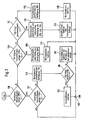
- Fig. 2 is an embodiment of a schematic Process carried out cyclically in a control unit Control of a braking system shown, in which the Service brake also based on brake signals a parking brake control device can be controlled.
- a brake signal S1 is output. If no brake signal S1 in a next step 101, it is checked whether a brake signal S2 from the parking brake operating device is issued. There is neither a brake signal S1 nor Brake signal S2 before, it is assumed that no Brake intervention is requested by the driver, and the process ended at point 102.
- Step 101 shows that a by the parking brake operating device predetermined brake signal S2 is present, is based on in a step 103 the brake signal S2 corresponding to the driver's brake request Brake setpoint generated.
- Step 104 checks whether the service brake operator is still functional. If the service brake control device works, in a step 105 the Parking brake system corresponding to that in step 103 generated braking setpoint activated. However, the results in Step 104 performed a check that a malfunction of the Service brake operating device is present in a step 106 queries whether the vehicle speed is above a predetermined threshold x1. This Threshold can e.g. at 5 km / h or less. If the vehicle speed is below the set Threshold, it is assumed that the driver primarily wants to park the vehicle and the parking brake system in step 105 corresponds to that in step 103 generated braking setpoint activated.
- a predetermined threshold x1 This Threshold can e.g. at 5 km / h or less.
- Step 106 shows that the Vehicle speed above the set threshold x1 is, instead of the parking brake system in one Step 107 the service brake system according to that in Step 103 generated brake setpoint activated.
- the higher functions ABS, Driving dynamics control, etc.
- ABS Driving dynamics control
- Speed threshold x1 the service brake system and down the vehicle speed x1 the parking brake system activated. This means that the driver is in the vehicle Can safely shutdown. Not a jerky one Braking when switching from the service brake function to get the parking brake function, for example the total vehicle deceleration at the switchover point is generated by the service brake system, of similar size Total vehicle deceleration of the parking brake system adjusted or controlled. Instead of the total vehicle deceleration can also apply braking forces or braking torques as a criterion for the generation of a jerk-free Transition can be chosen. Will the speed threshold x1, however, chosen so small that a jerky transition will not be felt by the driver at all, can adapt to the vehicle deceleration in Switchover point can be dispensed with.
- the vehicle speed in the vehicle known and also e.g. of different control units as Input information is needed is not a huge effort for the provision of this information as a switchover criterion between the service brake and parking brake actuation required. So the vehicle speed e.g. for the ABS function from the signals from Wheel speed sensors are calculated and are therefore available. If the vehicle speed information fails, then only the parking brake is activated without a Effect on the service brake system takes place.
- step 100 shows a through the Service brake operating device predetermined brake signal S1 is determined
- a next step 108 Query whether the parking brake operating device a brake signal S2 is specified. If not is assumed that the driver is actuating the service brake system wishes. Therefore, in one step 109 based on the brake signal S1 the driver's brake request corresponding brake setpoint generated and in one The next step 110 is the service brake system corresponding to the brake setpoint generated in step 109 activated.
- step 111 whether the vehicle speed is above a threshold x2. If this is not the case, then in a step 112 Brake request generation from a link of the Service brake and parking brake actuation by the Driver. The link is made so that the resulting Value greater than or equal to the minimum of both braking requests. This can take the form of a maximum or, for example The two values are averaged. Subsequently is resulting with this in a step 113 Brake setpoint the service brake system and the parking brake system activated.
- step 111 shows that the Vehicle speed is greater than the threshold value x2, is based on that by the service brake operator predetermined brake signal S2 in one next step 114 the driver's brake request corresponding brake setpoint generated. Then in a step 115 the service brake system according to the Brake setpoint generated in step 114 activated.
- the vehicle speed threshold x1 set equal to the vehicle speed threshold x2 become.
- the procedure described with reference to FIGS. 2 and 3 can also be modified so that initially the parking brake control and then the Service brake control device is queried.
- the parking brake operating device is also can be operated manually or by foot pedal.
Landscapes
- Engineering & Computer Science (AREA)
- Transportation (AREA)
- Mechanical Engineering (AREA)
- Valves And Accessory Devices For Braking Systems (AREA)
- Regulating Braking Force (AREA)
Description
Die Erfindung betrifft ein elektrisch betätigbares Bremssystem für Kraftfahrzeuge und ein Verfahren zu seiner Ansteuerung.The invention relates to an electrically operated Brake system for motor vehicles and a method for its Control.
Kraftfahrzeuge sind üblicherweise mit einer durch ein Bremspedal betätigbaren Betriebsbremsanlage und einer durch einen Handhebel oder ein Fußpedal betätigbaren Feststellbremsanlage ausgestattet. Während die Feststellbremsanlage in der Regel zur Sicherung eines haltenden oder abgestellten Fahrzeugs gegen Wegrollen dient, hat die Betriebsbremsanlage die Aufgabe, die Geschwindigkeit eines Fahrzeugs im Normalbetrieb zu verringern oder das Fahrzeug zum Stillstand zu bringen. Zur Verbesserung der Betriebssicherheit sind moderne Betriebsbremsanlagen vielfach mit zusätzlichen Systemen, wie z.B. ABS, ASR, Fahrdynamikregelungen, Bremsassistent und dgl., ausgestattet. In jüngerer Zeit sind elektrisch betätigbare Bremsanlagen für Kraftfahrzeuge bekannt geworden, bei denen die Betätigung eines Bremspedals durch eine Sensoreinrichtung erfaßt und in entsprechende Eingangssignale für eine Steuereinheit zur Ansteuerung der Betriebsbremsanlage umgewandelt wird. Ein Nachteil eines derartigen Steuerungskonzepts besteht allerdings darin, daß beim Ausfall der die Bremspedalbetätigung erfassenden Sensoreinrichtung auch die Betriebsbremsanlage ausfällt und eine Bremsung nur über die in der Regel auf die Hinterachse wirkende Feststellbremsanlage erreicht werden kann. Besonders bei einer allein durch die Feststellbremsanlage bewirkten Abbremsung eines Fahrzeugs mit höherer Geschwindigkeit sind jedoch die entsprechenden Radbremsen der Feststellbremsanlage einer großen Belastung ausgesetzt, was zu einem erheblichen Verschleiß der Radbremsen führen kann. Da die Zusatzsysteme, wie ABS, Bremsassistent usw., darüber hinaus nicht auf die üblichen Feststellbremsanlagen wirken, können die Hinterräder sogar blockieren, wodurch die Fahrstabilität beeinträchtigt und das Fahrzeug ins Schleudern geraten kann.Motor vehicles are usually one by one Brake pedal operated service brake system and one by a hand lever or a foot pedal operated parking brake system fitted. During the parking brake system usually to secure a holding or parked The service brake system has a vehicle that prevents it from rolling away the task of the speed of a vehicle in normal operation to decrease or the vehicle to a stop bring. To improve operational safety are modern service brake systems often with additional ones Systems such as ABS, ASR, vehicle dynamics controls, Brake assistant and the like. Are more recent electrically operated brake systems for motor vehicles become known in which the actuation of a brake pedal detected by a sensor device and in corresponding Input signals for a control unit for controlling the Service brake system is converted. A disadvantage of one Such a control concept, however, is that if the brake pedal actuation fails Sensor device also fails the service brake system and braking only on the usually on the rear axle acting parking brake system can be achieved. Especially with the parking brake system alone caused braking of a vehicle with higher However, speed is the corresponding wheel brakes the parking brake system is exposed to a large load, which lead to considerable wear of the wheel brakes can. Since the additional systems, such as ABS, brake assist, etc., moreover not on the usual parking brake systems can even block the rear wheels, causing the Driving stability impaired and the vehicle ins Can get skid.
Ein elektrisch betätigbares Bremssystem gemäß dem Oberbegriff des Anspruchs 1 ist aus DE-A-34 44 301 bekannt.An electrically actuated brake system according to the preamble of claim 1 is known from DE-A-34 44 301.
Aufgabe der Erfindung ist es, ein elektrisch betätigbares Bremssystem für Kraftfahrzeuge und ein Verfahren zu seiner Ansteuerung zu schaffen, durch die eine erhöhte Zuverlässigkeit und eine Verbesserung der Betriebssicherheit ermöglicht wird.The object of the invention is to provide an electrically operated Brake system for motor vehicles and a method for its To create control through which an increased Reliability and an improvement in operational security is made possible.
Diese Aufgabe wird gemäß den Merkmalen der unabhängigen Patentansprüche gelöst. Vorteilhafte Ausgestaltungen und zweckmäßige Fortbildungen der Erfindung sind in den abhängigen Patentansprüchen angegeben.This task is carried out according to the characteristics of the independent Claims resolved. Advantageous configurations and expedient developments of the invention are in the dependent claims.
In einer besonders einfachen Ausführung der Erfindung kann die zusätzliche Bremsbedieneinrichtung z.B. mit Hilfe eines manuell betätigbaren Schalters realisiert werden, der im Armaturenbrett, am Lenkrad oder einer sonstigen geeigneten Stelle angeordnet ist und durch den Fahrer im Bedarfsfall betätigt wird. Durch Betätigung des in der Regel für den Notfall gedachten Schalters kann ein entsprechendes Bremssignal einer Steuereinheit der Betriebsbremsanlage zugeführt werden, die daraufhin einen fest eingestellten Bremssollwert, z.B. in Form einer Verzögerung, eines Bremsmomentes, einer Spannkraft usw., vorgibt. In diesem Fall könnte auch die Warnblinkanlage aktiviert werden, da dieser Schalter hauptsächlich für Notfälle gedacht ist. Durch erneute Betätigung des Schalters kann der Bremsvorgang abgebrochen werdenIn a particularly simple embodiment of the invention the additional brake control device e.g. with help of a manually operated switch can be realized in the Dashboard, on the steering wheel or other suitable Place is arranged and by the driver if necessary is operated. By pressing the for the An emergency switch can be a corresponding one Brake signal from a control unit of the service brake system are fed, which then have a fixed Brake setpoint, e.g. in the form of a delay, one Braking torque, a clamping force, etc., specifies. In this In this case, the hazard warning lights could also be activated because this switch is mainly intended for emergencies. The braking process can be repeated by pressing the switch be canceled
Die Steuereinheit der Betriebsbremsanlage kann aber auch so konzipiert sein, daß bei einer Betätigung des Schalters anstelle eines festen Bremssollwertes oder einer festen Bremsverzögerung ein mit der Dauer der Betätigung kontinuierlich zunehmender Bremssollwert bzw. eine Bremsverzögerung eingestellt wird, bis ein definierter Maximalwert erreicht ist. Eine derartige Zunahme kann beispielsweise linear oder progressiv verlaufen.The control unit of the service brake system can also do so be designed that when the switch is actuated instead of a fixed brake setpoint or a fixed one Braking delay on with the duration of the actuation continuously increasing brake setpoint or one Brake deceleration is set until a defined one Maximum value is reached. Such an increase can for example, linear or progressive.
Es ist allerdings auch möglich, daß bei einer Betätigung des Schalters die Verzögerung bzw. Geschwindigkeitsverringerung in Abhängigkeit von der Fahrzeuggeschwindigkeit eingestellt wird. Je höher die Fahrzeuggeschwindigkeit, desto stärker erfolgt der Bremseingriff der Betriebsbremsanlage.However, it is also possible that when the Switch the deceleration or speed reduction set depending on the vehicle speed becomes. The higher the vehicle speed, the stronger the service brake system intervenes.
In einer besonders zweckmäßigen Ausführung der Erfindung kann die zweite Bremsbedieneinrichtung auch als Sensoreinheit mit mehreren, vorzugsweise redundant und diversitär aufgebauten Sensoren aufgebaut sein, durch die z.B. der Verstellweg und die Betätigungskraft eines als Hebel, Pedal, Druckknopf oder dgl. ausgebildeten zweiten Bremsbedienelements erfaßt wird. Dadurch kann der Steuereinheit ein durch den Fahrer veränderbares Bremssignal vorgegeben werden, das in der Steuereinheit verarbeitet und in entsprechende Bremssollwerte für die Betätigung der Radbremsen umgewandelt wird. Damit kann auch über das zweite Bremsbedienelement eine dosierte Betätigung der Betriebsbremsanlage erreicht werden.In a particularly expedient embodiment of the invention can the second brake control device as Sensor unit with several, preferably redundant and diversified sensors, through which e.g. the adjustment path and the actuating force of an as Lever, pedal, push button or the like. Trained second Brake control element is detected. This allows the Control unit a brake signal that can be changed by the driver be specified, processed in the control unit and in corresponding brake setpoints for actuating the Wheel brakes is converted. It can also be used for the second Brake control a metered actuation of the Service brake system can be reached.
In einer weiteren vorteilhaften Ausführungsform kann das zweite Bremsbedienelement an die Ergonomie der Hand angepaßt sein und ein aktives Element enthalten, mit der eine Rückkopplung des Bremsvorgangs im Sinne einer ansteigenden Widerstandskraft bei zunehmenden Bremswert simuliert: werden kann. Dadurch kann dem Fahrer ein Gefühl für den Bremsvorgang vermittelt werden, was zur Erhöhung des Bedienungskomforts beiträgt.In a further advantageous embodiment, the second brake control adapted to the ergonomics of the hand be and contain an active element with which one Feedback of the braking process in the sense of an increasing Resistance force simulated with increasing braking value: are can. This can give the driver a feel for the Braking process are conveyed, which increases the Ease of use contributes.
Aus Sicherheitsgesichtspunkten wird die Funktionsweise der beiden Bremsbedieneinrichtungen durch eine bevorzugt redundant aufgebaute Überwachungseinrichtung überprüft, wobei z.B. bei einem erkannten Ausfall einer als Bremspedalsimulator aufgebauten ersten Bremsbedieneinrichtung eine akustische und/oder visuelle Warneinrichtung aktiviert werden kann. Dadurch kann dem Fahrer angezeigt werden, daß die Fußbetätigung der Betriebsbremse nicht mehr funktioniert und daß die Betriebsbremse über die z.B. manuell betätigbare zweite Bremsbedieneinrichtung aktiviert werden muß.The functionality of the preferred two brake control devices by one redundant monitoring device checked, where e.g. if a failure is identified as a Brake pedal simulator constructed first brake control device an acoustic and / or visual warning device can be activated. This can be displayed to the driver be that the foot actuation of the service brake is no longer works and that the service brake via the e.g. manually operated second brake control device activated must become.
In einer weiteren besonders zweckmäßigen Ausführungsform der Erfindung können auch durch eine Feststellbremsbedieneinrichtung vorgegebene Bremssignale zur Ansteuerung einer Betriebsbremsanlage genutzt werden. Dabei können z.B. die Sensoren und/oder Schalter zur Erfassung der Bedienung einer elektrisch betätigbaren Feststellbremse verwendet werden, wodurch sich Kostenvorteile ergeben. Allerdings sind hier entsprechende Maßnahmen für eine Zuordnung zwischen der Betätigung eines Feststellbremsbedienelements und der Aktivierung der Betriebsbremsanlage und/oder Feststellbremsanlage erforderlich. Eine zweckmäßige Zuordnung kann z.B. über die Fahrzeuggeschwindigkeit derart erfolgen, daß durch Betätigung des Feststellbremsbedienelements oberhalb einer vorgegebenen Fahrzeuggeschwindigkeit die Betriebsbremsanlage und unterhalb der vorgegebenen Fahrzeuggeschwindigkeit die Feststellbremsanlage aktiviert wird. Dadurch kann auch bei Ausfall einer z.B. als Bremspedalmodul ausgebildeten Betriebsbremsbedieneinrichtung über die Betätigung der Feststellbrembedieneinrichtung eine Bremsung mit Hilfe der Betriebsbremsanlage eingeleitet werden. Dabei kann auch ein Eingriff der zusätzlichen Funktionen der Betriebsbremsanlage, wie ABS, ESP, Fahrdynamikregelung und dgl., erfolgen. Es wird außerdem sichergestellt, daß die Feststellbremsanlage nicht bei einer höheren Fahrzeuggeschwindigkeit zum Einsatz gelangt und dabei zu stark belastet wird. Trotzdem ist gewährleistet, daß der Fahrer sein Fahrzeug im Stillstand sicher durch die Feststellbremse abstellen kann.In a further particularly expedient embodiment of the Invention can also by a parking brake control device predetermined brake signals to control a Service brake system can be used. Here, e.g. the Sensors and / or switches for detecting the operation of a electrically operated parking brake can be used which results in cost advantages. However, are here appropriate measures for an assignment between the Actuation of a parking brake control and Activation of the service brake system and / or parking brake system required. An appropriate assignment can e.g. about the vehicle speed in such a way that by actuating the parking brake control element above a predetermined vehicle speed Service brake system and below the specified Vehicle speed activated the parking brake system becomes. This means that even if a e.g. as Brake pedal module trained service brake control device via the actuation of the parking brake operating device Braking initiated using the service brake system become. An intervention of the additional Functions of the service brake system, such as ABS, ESP, Driving dynamics control and the like. It will also ensures that the parking brake system is not at a higher vehicle speed is used and is overburdened. Still is ensures that the driver stops his vehicle can park safely using the parking brake.
Weitere Besonderheiten und Vorzüge der Erfindung ergeben sich aus der folgenden Beschreibung vorteilhafter Ausführungsformen anhand der Zeichnung. Es zeigen:
- Fig. 1
- eine schematische Blockdarstellung eines erfindungsgemäßen Bremssystems;
- Fig. 2
- ein Flußdiagramm, das ein erstes Ausführungsbeispiel einer Abarbeitung in einer Steuereinheit zeigt und
- Fig. 3
- ein Flußdiagramm, das ein zweites Ausführungsbeispiel einer Abarbeitung in einer Steuereinheit zeigt.
- Fig. 1
- a schematic block diagram of a brake system according to the invention;
- Fig. 2
- a flowchart showing a first embodiment of a processing in a control unit and
- Fig. 3
- a flowchart showing a second embodiment of processing in a control unit.
Fig. 1 zeigt schematisch eine nach dem Brake-by-Wire-Konzept
aufgebaute Betriebsbremsanlage 1, bei der eine Steuereinheit
2 über eine Signalleitung 3 mit einer ersten
Bremsbedieneinrichtung 4 und über eine Signalleitung 5 mit
einer zweiten Bremsbedieneinrichtung 6 verbunden ist. Die
erste Bremsbedieneinrichtung 4 kann z.B. ein Bremspedalmodul
sein, bei dem die Betätigung eines Bremspedals 7 durch eine
Sensoreinrichtung 8 erfaßt und in entsprechende Bremssignale
S1 zur Ansteuerung der Betriebsbremsanlage 1 umgewandelt
wird. Die zweite Bremsbedieneinrichtung 6 kann ebenfalls
eine Sensoreinrichtung 9 zur Erfassung der Betätigung z.B.
eines Handhebels 10 und Vorgabe entsprechender Bremssignale
S2 aufweisen.Fig. 1 shows schematically one according to the brake-by-wire concept
built service brake system 1, in which a
Von der Steuereinheit 2 werden die durch die beiden
Bremsbedieneinrichtungen 4 und 6 vorgegeben Bremssignale in
entsprechende Bremssollwerte für die Ansteuerung der
Radbremsen 11 bis 14 umgewandelt. Bei der Vorgabe der
Bremssollwerte können von der Steuereinheit 2 zur
Realisierung sicherheitsrelevanter Zusatzfunktionen, wie
z.B. ABS, Bremsassistent, Fahrstabilitätsregelung usw., auch
durch nicht dargestellte Sensoren ermittelte
Zusatzinformationen, wie z.B. Fahrzeuggeschwindigkeit,
Querbeschleunigung, oder Gierwinkelgeschwindigkeit
berücksichtigt werden. From the
Die Betriebsbremsanlage 1 kann sowohl von der als Bremspedalmodul ausgebildeten ersten Bremsbedieneinrichtung 4 als auch von der zweiten Bremsbedieneinrichtung 6 angesteuert werden. Damit ist der Fahrer in der Lage, auch bei Ausfall des Bremspedalmoduls über die manuell bedienbare zweite Bremsbedieneinrichtung 6 einen Bremsvorgang mit Hilfe der Betriebsbremse einleiten.The service brake system 1 can both of the Brake pedal module designed first brake control device 4 and the second brake operating device 6 can be controlled. So the driver is able to, too in the event of failure of the brake pedal module via the manually operated second brake control device 6 using a braking process the service brake.
In einer weiteren Ausführungsform kann auch eine Feststellbremsbedieneinrichtung als zweite Bremsbedieneinrichtung für die Aktivierung der Betriebsbremsanlage genutzt werden.In a further embodiment, a parking brake operating device can also be used as a second brake control device for the activation of the service brake system can be used.
In Fig. 2 ist schematisch ein Ausführungsbeispiel für einen in einer Steuereinheit zyklisch durchgeführten Ablauf zur Ansteuerung eines Bremssystems gezeigt, bei dem die Betriebsbremse auch auf der Grundlage von Bremssignalen einer Feststellbremsbedieneinrichtung ansteuerbar ist.In Fig. 2 is an embodiment of a schematic Process carried out cyclically in a control unit Control of a braking system shown, in which the Service brake also based on brake signals a parking brake control device can be controlled.
Bei dem in Fig. 2 gezeigten Ablauf wird nach dem Start in
einem ersten Schritt 100 abgefragt, ob durch die z.B. als
Bremspedalmodul ausgeführte Betriebsbremsbedieneinrichtung
ein Bremsignal S1 ausgegeben wird. Falls kein Bremssignal S1
vorliegt, wird in einem nächsten Schritt 101 überprüft, ob
von der Feststellbremsbedieneinrichtung ein Bremssignal S2
ausgegeben wird. Liegt weder ein Bremssignal S1 noch ein
Bremssignal S2 vor, wird davon ausgegangen, daß kein
Bremseingriff durch den Fahrer gefordert wird, und der Ablauf
ist am Punkt 102 beendet.In the sequence shown in FIG. 2, after starting in
a
Ergibt allerdings die Abfrage im Schritt 101, daß ein durch
die Feststellbremsbedieneinrichtung vorgegebenes Bremssignal
S2 vorliegt, wird in einem Schritt 103 basierend auf
dem Bremssignal S2 ein dem Fahrerbremswunsch entsprechender
Bremssollwert generiert. Anschließend wird in einem weiteren
Schritt 104 überprüft, ob die Betriebsbremsbedieneinrichtung
noch funktionstüchtig ist. Wenn die Betriebsbremsbedieneinrichtung
funktioniert, wird in einem Schritt 105 die
Feststellbremsanlage entsprechend dem im Schritt 103
generierten Bremssollwert aktiviert. Ergibt jedoch die im
Schritt 104 durchgeführte Überprüfung, daß eine Störung der
Betriebsbremsbedieneinrichtung vorliegt, wird zunächst in
einem Schritt 106 abgefragt, ob die Fahrzeuggeschwindigkeit
über einem vorgegebenen Schwellenwert x1 liegt. Dieser
Schwellenwert kann z.B. bei 5 km/h oder darunter liegen.
Wenn die Fahrzeuggeschwindigkeit unter dem festgelegten
Schwellenwert liegt, wird davon ausgegangen, daß der Fahrer
das Fahrzeug primär abstellen will und die Feststellbremsanlage
wird im Schritt 105 entsprechend dem in Schritt 103
generierten Bremssollwert aktiviert.However, the query in
Wenn allerdings die Abfrage im Schritt 106 ergibt, daß die
Fahrzeuggeschwindigkeit über dem festgelegten Schwellenwert
x1 liegt, wird anstelle der Feststellbremsanlage in einem
Schritt 107 die Betriebsbremsanlage entsprechend dem im
Schritt 103 generierten Bremssollwert aktiviert. Dadurch
können ggf. auch die höheren Funktionen (ABS,
Fahrdynamikregelung usw.) zum Einsatz gelangen, um z.B. ein
Blockieren der Räder zu verhindern. Darüber hinaus wird
vermieden, daß ein Fahrer bei zu hoher Geschwindigkeit die
Feststellbremsanlage aktiviert, wodurch diese stark
beansprucht wird und sogar defekt werden könnte. However, if the query in
Bremst der Fahrer sein Fahrzeug durch Betätigung der Feststellbremsbedieneinrichtung ab, so wird oberhalb der Geschwindigkeitsschwelle x1 die Betriebsbremsanlage und ab der Fahrzeugeschwindigkeit x1 die Feststellbremsanlage aktiviert. Das bedeutet, daß der Fahrer sein Fahrzeug im Stillstand sicher abstellen kann. Um keine ruckartige Bremsung bei der Umschaltung von der Betriebsbremsfunktion auf die Feststellbremsfunktion zu erhalten, kann beispielsweise die Gesamtfahrzeugverzögerung im Umschaltpunkt, die von der Betriebsbremsanlage erzeugt wird, ähnlich groß der Gesamtfahrzeugverzögerung der Feststellbremsanlage eingeregelt oder eingesteuert werden. Anstelle der Gesamtfahrzeugverzögerung können auch Bremskräfte oder Bremsmomente als Kriterium für die Erzeugung eines ruckfreien Übergangs gewählt werden. Wird die Geschwindigkeitsschwelle x1 allerdings so klein gewählt, daß ein ruckartiger Übergang erst gar nicht vom Fahrer wesentlich spürbar auftreten wird, kann auf die Anpassung der Fahrzeugverzögerung im Umschaltpunkt verzichtet werden.If the driver brakes his vehicle by pressing the Parking brake control device, so above Speed threshold x1 the service brake system and down the vehicle speed x1 the parking brake system activated. This means that the driver is in the vehicle Can safely shutdown. Not a jerky one Braking when switching from the service brake function to get the parking brake function, for example the total vehicle deceleration at the switchover point is generated by the service brake system, of similar size Total vehicle deceleration of the parking brake system adjusted or controlled. Instead of the total vehicle deceleration can also apply braking forces or braking torques as a criterion for the generation of a jerk-free Transition can be chosen. Will the speed threshold x1, however, chosen so small that a jerky transition will not be felt by the driver at all, can adapt to the vehicle deceleration in Switchover point can be dispensed with.
Da in der Regel die Fahrzeugeschwindigkeit im Fahrzeug bekannt und auch z.B. von verschiedenen Steuergeräten als Eingangsinformation benötigt wird, ist kein großer Aufwand für die Bereitstellung dieser Information als Umschaltkriterium zwischen der Betriebsbrems- und Feststellbremsbetätigung erforderlich. So wird die Fahrzeuggeschwindigkeit z.B. für die ABS-Funktion aus den Signalen von Raddrehzahlsensoren berechnet und steht somit zur Verfügung. Fällt die Fahrzeuggeschwindigkeitsinformation aus, so wird nur noch die Feststellbremse aktiviert, ohne daß eine Wirkung auf die Betriebsbremsanlage erfolgt. As a rule, the vehicle speed in the vehicle known and also e.g. of different control units as Input information is needed is not a huge effort for the provision of this information as a switchover criterion between the service brake and parking brake actuation required. So the vehicle speed e.g. for the ABS function from the signals from Wheel speed sensors are calculated and are therefore available. If the vehicle speed information fails, then only the parking brake is activated without a Effect on the service brake system takes place.
Wenn hingegen bei der Abfrage im Schritt 100 ein durch die
Betriebsbremsbedieneinrichtung vorgegebenes Bremssignal S1
ermittelt wird, folgt in einem nächsten Schritt 108 eine
Abfrage, ob auch durch die Feststellbremsbedieneinrichtung
ein Bremssignal S2 vorgegeben wird. Wenn dies nicht der Fall
ist, wird davon ausgegangen, daß der Fahrer eine Betätigung
der Betriebsbremsanlage wünscht. Daher wird in einem Schritt
109 basierend auf dem Bremsignal S1 ein dem Fahrerbremswunsch
entsprechender Bremssollwert generiert und in einem
nächsten Schritt 110 wird die Betriebsbremsanlage
entsprechend dem im Schritt 109 generierten Hremssollwert
aktiviert.If, on the other hand, the query in
Wenn sich allerdings durch die Abfrage in den Schritten 100
und 108 ergibt, daß sowohl durch die Betriebsbremsbedieneinrichtung
als auch durch die Feststellbremsbedieneinrichtung
Bremssignale S1 und S2 vorgegeben werden,
wird in einem Schritt 111 überpüft, ob die Fahrzeuggeschwindigkeit
über einem Schwellenwert x2 liegt. Wenn dies
nicht der Fall ist, erfolgt in einem Schritt 112 die
Bremswunschgenerierung aus einer Verknüpfung der
Betriebsbrems- und Feststellbremsbetätigung durch den
Fahrer. Die Verknüpfung erfolgt so, daß der resultierende
Wert größer gleich dem Minimum aus beiden Bremswünschen ist.
Dies kann beispielsweise in Form einer Maximumsbildung oder
Durchschnittsbildung beider Werte erfolgen. Anschließend
wird in einem Schritt 113 mit diesem resultierenden
Bremssollwert die Betriebsbremsanlage und die Feststellbremsanlage
aktiviert.However, if the query in
Ergibt hingegen die Abfrage im Schritt 111, daß die
Fahrzeuggeschwindigkeit größer als der Schwellenwert x2 ist,
wird auf der Grundlage des durch die Betriebsbremsbedieneinrichtung
vorgegebenen Bremssignals S2 in einem
nächsten Schritt 114 ein dem Fahrerbremswunsch
entsprechender Bremssollwert generiert. Anschließend wird in
einem Schritt 115 die Betriebsbremsanlage entsprechend dem
in Schritt 114 generierten Bremssollwert aktiviert.On the other hand, the query in
Der in Fig. 3 dargestellte Ablauf entspricht im wesentlichen
dem Ablauf gemäß Fig. 2, so daß die übereinstimmenden
Schritte mit denselben Bezugszeichen versehen sind. Im
Unterschied zur Ausführung nach Fig. 2 wird bei der
Ausführung gemäß Fig. 3 auf den Schritt 104 zur Vereinfachung
verzichtet. Das bedeutet, daß die Abfrage nach der
Funktionsfähigkeit der Betriebsbremsbedieneinrichtung
entfällt. Es erfolgt vielmehr im Anschluß an den Schritt 103
der Abfrageschritt 106, in dem die Unterscheidung zwischen
der Aktivierung der Feststell- oder Betriebsbremse in
Abhängigkeit vom Schwellenwert x1 der Fahrzeuggeschwindigkeit
erfolgt.The sequence shown in Fig. 3 corresponds essentially
2, so that the matching
Steps are provided with the same reference numerals. in the
Difference to the embodiment of FIG. 2 is in the
3 to step 104 for simplification
waived. This means that the query for the
Functionality of the service brake control device
eliminated. Rather, it takes place after
Bei einer weiteren vereinfachten Ausführung von Fig. 2 und Fig. 3 kann der Fahrzeuggeschwindigkeitsschwellenwert x1 gleich dem Fahrzeuggeschwindigkeitsschwellenwert x2 gesetzt werden. Die anhand der Fig. 2 und 3 beschriebene Vorgehensweise kann auch dahingehend abgewandelt werden, daß zunächst die Feststellbremsbedieneinrichtung und dann die Betriebsbremsbedieneinrichtung abgefragt wird.In a further simplified embodiment of Fig. 2 and 3, the vehicle speed threshold x1 set equal to the vehicle speed threshold x2 become. The procedure described with reference to FIGS. 2 and 3 can also be modified so that initially the parking brake control and then the Service brake control device is queried.
Obwohl in der Regel die Betriebsbremsbedieneinrichtung über eine Fußbetätigung erfolgt, könnte diese auch manuell erfolgen. Auch die Feststellbremsbedieneinrichtung ist manuell oder durch Fußpedal betätigbar.Although usually the service brake control device over a foot operation takes place, this could also be done manually respectively. The parking brake operating device is also can be operated manually or by foot pedal.
Claims (9)
- Electrically operable brake system for automotive vehicles with a first brake operating device (4) for sensing the actuation of a first brake operating element (7) and for specifying corresponding brake signals (S1), a second brake operating device (6) operable by the driver for specifying corresponding brake signals (S2), and a service brake system (1) which can be activated on the basis of the brake signals (S1, S2) predetermined by the first brake operating device (4) and the second brake operating device (6), wherein the second brake operating device (6) comprises at least one switching element and/or a sensor device (9) with at least one sensor for sensing the actuation of a second brake operating element (10), and wherein the service brake system (1) comprises at least one control unit (2) for converting the brake signals (S2) predetermined by the second brake operating device (6) into nominal brake values for the actuation of corresponding service brakes (11, 12, 13, 14),
characterized in that a fixed nominal brake value, or a nominal brake value rising up to a maximum value, or a vehicle-speed responsive nominal brake value is predetermined for the actuation of the service brakes by the control unit (2) upon activation of the second brake operating device (6). - Brake system as claimed in claim 1,
characterized in that each of the service brakes (11, 12, 13, 14) comprises at least one control unit for converting the brake signals (S2) predetermined by the second brake operating device (6) into brake force. - Brake system as claimed in claim 1,
characterized in that a nominal brake value which is responsive to the activation of a second brake operating element (10) is predetermined by the control unit (2) for the actuation of the service brakes (11, 12, 13, 14). - Brake system as claimed in claim 3,
characterized in that associated with the second brake operating element (10) is an active element for the simulation of the brake effect. - Brake system as claimed in any one of claims 1 to 4,
characterized in that the function of the first and second brake operating device (4, 6) can be tested by a monitoring device. - Brake system as claimed in any one of claims 1 to 4,
characterized in that the second brake operating device (6) is the operating device of an electrically operable parking brake which permits activating the service brake system (1) above a predetermined vehicle speed. - Method for the actuation of an electrically operable brake system for automotive vehicles, wherein the activation of a service brake system and/or a parking brake system is effected on the basis of brake signals of a service brake operating device operable by the driver and brake signals of a parking brake operating device,
characterized in that the service brake system is activated by the activation of the parking brake device above a predetermined vehicle speed. - Method as claimed in claim 7,
characterized in that a function test of the service brake operating device is performed prior to the activation of the service brake system by the parking brake operating device. - Method as claimed in claim 7 or 8,
characterized in that, in the event of simultaneous provision of brake signals of the service brake operating device and the parking brake operating device, the service brake system is activated above a predetermined vehicle speed and the service brake system and the parking brake system are activated below the predetermined vehicle speed.
Applications Claiming Priority (3)
| Application Number | Priority Date | Filing Date | Title |
|---|---|---|---|
| DE19826687 | 1998-06-16 | ||
| DE19826687A DE19826687A1 (en) | 1998-06-16 | 1998-06-16 | Electrically actuated brake system for motor vehicles and method for its control |
| PCT/EP1999/004133 WO1999065746A1 (en) | 1998-06-16 | 1999-06-15 | Electrically controlled braking system and associated control method |
Publications (2)
| Publication Number | Publication Date |
|---|---|
| EP1087880A1 EP1087880A1 (en) | 2001-04-04 |
| EP1087880B1 true EP1087880B1 (en) | 2002-04-24 |
Family
ID=7870988
Family Applications (1)
| Application Number | Title | Priority Date | Filing Date |
|---|---|---|---|
| EP99929221A Expired - Lifetime EP1087880B1 (en) | 1998-06-16 | 1999-06-15 | Electrically controlled braking system and associated control method |
Country Status (5)
| Country | Link |
|---|---|
| US (1) | US6626271B1 (en) |
| EP (1) | EP1087880B1 (en) |
| JP (1) | JP2002518241A (en) |
| DE (2) | DE19826687A1 (en) |
| WO (1) | WO1999065746A1 (en) |
Cited By (1)
| Publication number | Priority date | Publication date | Assignee | Title |
|---|---|---|---|---|
| CN110040000A (en) * | 2019-04-25 | 2019-07-23 | 浙江吉利控股集团有限公司 | Method for recovering brake energy, brake energy recovering system and vehicle |
Families Citing this family (47)
| Publication number | Priority date | Publication date | Assignee | Title |
|---|---|---|---|---|
| US5941608A (en) | 1996-03-07 | 1999-08-24 | Kelsey-Hayes Company | Electronic brake management system with manual fail safe |
| DE19954284B4 (en) * | 1999-11-11 | 2018-06-14 | Robert Bosch Gmbh | Electrically controlled braking system for a vehicle |
| DE10006656C1 (en) * | 2000-02-15 | 2001-06-07 | Siemens Ag | Electric parking brake for motor vehicle guarantees regulated braking of vehicle by dynamically operating parking brake at low cost |
| DE10033835B4 (en) * | 2000-07-12 | 2013-05-02 | Continental Teves Ag & Co. Ohg | Brake system for a motor vehicle and method for its control |
| DE10052502A1 (en) * | 2000-10-23 | 2002-04-25 | Continental Teves Ag & Co Ohg | Automobile braking system control method has braking force provided by active braking device applied to vehicle wheel acted on by stationary brake shortly before vehicle standstill |
| FR2830826B1 (en) * | 2001-10-16 | 2004-03-26 | Delphi Tech Inc | PARKING AND EMERGENCY BRAKING SYSTEM AND METHOD FOR IMPLEMENTING IT |
| DE10213346B4 (en) * | 2002-03-01 | 2017-10-19 | Continental Teves Ag & Co. Ohg | Method for controlling a motor vehicle brake system |
| DE10224688A1 (en) * | 2002-06-04 | 2003-12-18 | Bosch Gmbh Robert | Stationary brake operating method for automobile electromechanical braking system, uses movement sensor for preventing operation of stationary brake during movement of automobile |
| DE10256490B4 (en) * | 2002-07-24 | 2005-03-03 | Gratza, Peter, Dipl.-Ing. | Method for spontaneously reducing the speed of a motor vehicle |
| US20040108769A1 (en) * | 2002-12-05 | 2004-06-10 | Marathe Sameer S. | Automatic secondary brake application |
| US20040140710A1 (en) * | 2003-01-17 | 2004-07-22 | Delphi Technologies Inc. | Apparatus and method for controlling an electric park brake |
| FR2850923B1 (en) * | 2003-02-07 | 2006-04-28 | Peugeot Citroen Automobiles Sa | METHOD FOR MANAGING THE CONDITION AND OPERATION OF A MOTOR VEHICLE AND SYSTEM FOR CARRYING OUT SAID METHOD |
| DE10324808B4 (en) * | 2003-06-02 | 2005-10-20 | Bosch Gmbh Robert | Optimized controller configuration for a car parking brake |
| DE10325650A1 (en) * | 2003-06-06 | 2004-12-23 | Daimlerchrysler Ag | Braking device and method for a vehicle |
| DE10351026B3 (en) * | 2003-10-31 | 2005-06-30 | Lucas Automotive Gmbh | A method of stabilizing a stalled motor vehicle and brake system for carrying out the method |
| US7500687B2 (en) * | 2004-01-31 | 2009-03-10 | Lockheed Martin Corporation | Vehicle suspension systems |
| DE102004010743A1 (en) * | 2004-03-05 | 2006-01-19 | Wabco Gmbh & Co.Ohg | Electrically controlled pneumatic brake system for a vehicle |
| FR2869282B1 (en) * | 2004-04-21 | 2006-06-23 | Bosch Gmbh Robert | BRAKING DEVICE FOR MOTOR VEHICLE |
| WO2006027852A1 (en) * | 2004-09-09 | 2006-03-16 | Toyota Jidosha Kabushiki Kaisha | Semi brake-by-wire brake controller of vehicle |
| FR2878215B1 (en) * | 2004-11-25 | 2007-01-05 | Renault Sas | ELECTRIC BRAKE DEVICE FOR VEHICLE |
| DE102005015725A1 (en) * | 2005-04-06 | 2006-10-12 | Robert Bosch Gmbh | Determine the activation time of an automatic hold function |
| DE102005016001B4 (en) * | 2005-04-07 | 2022-08-18 | Robert Bosch Gmbh | Braking a vehicle during an emergency stop |
| DE102005051437A1 (en) * | 2005-10-27 | 2007-05-03 | Daimlerchrysler Ag | Device for operating a motor vehicle |
| JP4328976B2 (en) * | 2006-03-20 | 2009-09-09 | 三菱ふそうトラック・バス株式会社 | Control device for hybrid electric vehicle |
| US7393065B2 (en) * | 2006-06-01 | 2008-07-01 | Lockheed Martin Corporation | Redundant braking system |
| DE102006041008A1 (en) * | 2006-08-31 | 2008-03-06 | Wabco Gmbh | Pneumatic vehicle brake system and method for controlling such a brake system |
| US20080066613A1 (en) * | 2006-09-15 | 2008-03-20 | Lockheed Martin Corporation | Perforated hull for vehicle blast shield |
| US20080173167A1 (en) * | 2006-09-15 | 2008-07-24 | Armor Holdings | Vehicular based mine blast energy mitigation structure |
| DE102006048910A1 (en) * | 2006-10-17 | 2008-04-24 | Robert Bosch Gmbh | Fail-safe parking assistance system |
| JP4918847B2 (en) * | 2006-11-24 | 2012-04-18 | 株式会社アドヴィックス | Parking brake control device |
| DE102007021739A1 (en) * | 2007-05-09 | 2008-11-13 | Continental Automotive Gmbh | Stop and go operation of an electronic parking brake |
| DE102007046484A1 (en) * | 2007-09-28 | 2009-04-02 | Continental Automotive Gmbh | Method for controlling an electromechanical parking brake system of a vehicle |
| DE102008012387A1 (en) * | 2008-03-04 | 2009-09-10 | Lucas Automotive Gmbh | Control of an electrically actuated parking brake in case of failure of a speed signal |
| DE102008027730B4 (en) * | 2008-06-11 | 2015-08-13 | Knorr-Bremse Systeme für Nutzfahrzeuge GmbH | An electrically controlled parking brake system and method for operating an electrically controlled parking brake system |
| US8918261B2 (en) * | 2009-10-05 | 2014-12-23 | GM Global Technology Operations LLC | Dynamic parking brake methods and systems for motor vehicles |
| JP2012037047A (en) * | 2010-07-13 | 2012-02-23 | Nippon Dempa Kogyo Co Ltd | Braking device, transportation equipment and industrial equipment |
| FR2974544B1 (en) * | 2011-04-29 | 2014-04-11 | Peugeot Citroen Automobiles Sa | ELECTRIC BRAKE SYSTEM FOR A MOTOR VEHICLE |
| US9039102B2 (en) * | 2011-09-08 | 2015-05-26 | Goodrich Corporation | Systems and methods for emergency braking system |
| DE102014200046B4 (en) * | 2014-01-07 | 2016-09-01 | Volkswagen Aktiengesellschaft | Method for operating a controllable parking brake of a motor vehicle |
| CN104494588B (en) * | 2014-11-20 | 2017-04-26 | 南车株洲电力机车有限公司 | Control instruction generation method and system for wired electrically-controlled pneumatic braking |
| EP3337699A4 (en) * | 2015-09-12 | 2019-04-17 | GM Global Technology Operations LLC | Non-hydraulic feedback system for vehicle having a simulated brake pedal |
| CN106184163B (en) * | 2016-09-13 | 2018-09-04 | 北京汽车研究总院有限公司 | One kind automatically controlling parking braking system and automobile |
| DE102016015544A1 (en) | 2016-12-27 | 2018-06-28 | Lucas Automotive Gmbh | Motor vehicle control unit for an electric parking brake |
| DE102022104851A1 (en) | 2022-03-01 | 2023-09-07 | Zf Active Safety Gmbh | braking system |
| DE102022110059A1 (en) * | 2022-04-26 | 2023-10-26 | Audi Aktiengesellschaft | Method for operating a brake system for a motor vehicle and corresponding brake system |
| DE102022118673A1 (en) | 2022-07-26 | 2024-02-01 | Audi Aktiengesellschaft | Method for operating a brake system for a motor vehicle and corresponding brake system |
| DE102023106115A1 (en) | 2023-03-13 | 2024-09-19 | Bayerische Motoren Werke Aktiengesellschaft | Arrangement of at least one interface for an electronic coupling of at least one control device to a brake-by-wire system of a motor vehicle and method |
Family Cites Families (16)
| Publication number | Priority date | Publication date | Assignee | Title |
|---|---|---|---|---|
| US3838888A (en) | 1973-04-02 | 1974-10-01 | Syncro Corp | Electric brake controller |
| US4629043A (en) * | 1983-01-31 | 1986-12-16 | Mazda Motor Corporation | Electric parking brake system for a vehicle |
| DE3410006A1 (en) * | 1984-03-19 | 1985-09-19 | Alfred Teves Gmbh, 6000 Frankfurt | METHOD FOR CONTROLLING A BRAKE SYSTEM FOR MOTOR VEHICLES, AND DEVICE FOR IMPLEMENTING THE METHOD |
| DE3444301A1 (en) * | 1984-12-05 | 1986-06-12 | Alfred Teves Gmbh, 6000 Frankfurt | Electrically controlled and driven brake system for motor vehicles |
| DE3518715A1 (en) * | 1985-05-24 | 1986-11-27 | Daimler-Benz Ag, 7000 Stuttgart | Parking brake device |
| DE4004149A1 (en) | 1990-02-10 | 1991-08-14 | Bosch Gmbh Robert | Vehicle anti-locking braking regulator with auxiliary function - has regulator coupled to double=action hydraulic cylinder for handbrake via controlled valve |
| DE4029333A1 (en) | 1990-09-15 | 1992-03-19 | Teves Gmbh Alfred | Modular control for vehicle - has logic connections between pedal sensors and servo system for controls |
| US5139315A (en) * | 1991-02-28 | 1992-08-18 | General Motors Corporation | Vehicle parking brake system and method |
| DE4338064C1 (en) * | 1993-11-08 | 1995-03-16 | Daimler Benz Ag | Method for monitoring the functioning of a device for the performance of an automatic braking sequence |
| DE19548392C2 (en) | 1995-12-22 | 2001-05-17 | Siemens Ag | Brake system for a motor vehicle |
| JP2000501047A (en) * | 1996-09-19 | 2000-02-02 | ローベルト ボツシユ ゲゼルシヤフト ミツト ベシユレンクテル ハフツング | Apparatus and method for controlling driving system of automobile |
| JP3837195B2 (en) * | 1996-12-26 | 2006-10-25 | 曙ブレーキ工業株式会社 | Electric brake with pad clearance adjustment mechanism and pad clearance adjustment method |
| DE19813019A1 (en) * | 1998-03-25 | 1999-09-30 | Bosch Gmbh Robert | Method and device for controlling at least one driving dynamics variable of a vehicle |
| JPH11278250A (en) * | 1998-03-26 | 1999-10-12 | Toyota Motor Corp | Motor-driven parking brake device |
| US6183051B1 (en) * | 1999-02-01 | 2001-02-06 | Aircraft Braking Systems Corp. | Fail safe electrical brake control system for aircraft |
| US6293363B1 (en) * | 1999-06-16 | 2001-09-25 | Ford Global Technologies, Inc. | Integrated electronic shift and parking brake system, including security interlock, for motor vehicles |
-
1998
- 1998-06-16 DE DE19826687A patent/DE19826687A1/en not_active Withdrawn
-
1999
- 1999-06-15 US US09/719,922 patent/US6626271B1/en not_active Expired - Fee Related
- 1999-06-15 EP EP99929221A patent/EP1087880B1/en not_active Expired - Lifetime
- 1999-06-15 DE DE59901309T patent/DE59901309D1/en not_active Expired - Lifetime
- 1999-06-15 JP JP2000554597A patent/JP2002518241A/en active Pending
- 1999-06-15 WO PCT/EP1999/004133 patent/WO1999065746A1/en active IP Right Grant
Cited By (1)
| Publication number | Priority date | Publication date | Assignee | Title |
|---|---|---|---|---|
| CN110040000A (en) * | 2019-04-25 | 2019-07-23 | 浙江吉利控股集团有限公司 | Method for recovering brake energy, brake energy recovering system and vehicle |
Also Published As
| Publication number | Publication date |
|---|---|
| EP1087880A1 (en) | 2001-04-04 |
| US6626271B1 (en) | 2003-09-30 |
| JP2002518241A (en) | 2002-06-25 |
| DE59901309D1 (en) | 2002-05-29 |
| WO1999065746A1 (en) | 1999-12-23 |
| DE19826687A1 (en) | 1999-12-23 |
Similar Documents
| Publication | Publication Date | Title |
|---|---|---|
| EP1087880B1 (en) | Electrically controlled braking system and associated control method | |
| EP2117895B1 (en) | Method and devices for operating a motor vehicle brake device | |
| EP2250055B1 (en) | Controlling an electrically actuable parking brake in the event of failure of a speed signal | |
| DE602004000867T2 (en) | Device and method for operating an electric parking brake | |
| DE19621628A1 (en) | Method of controlling motor vehicle braking system | |
| EP1198374B1 (en) | Brake system for a motor vehicle | |
| EP0733532A2 (en) | Method for determining set pressure of a pressure-actuated brake in a vehicle brake system | |
| EP2162328B1 (en) | Automatic parking brake with slip controller | |
| EP1984224B1 (en) | Method and device for operating a motor vehicle | |
| EP0733531B1 (en) | Method for braking a vehicle | |
| EP1303432B1 (en) | Device and method for adjusting a setpoint deceleration of a vehicle | |
| EP0915787A2 (en) | Braking device | |
| EP1610991B1 (en) | Device and method for operating a motor-vehicle parking brake | |
| WO2005007474A1 (en) | Method for controlling a brake system and brake system for a vehicle | |
| EP1306277B1 (en) | Electrically controlled parking brake | |
| DE10224399B4 (en) | Vehicle with automatic distance control | |
| DE19822860C2 (en) | Method and device for braking a vehicle | |
| EP1391362A1 (en) | Electronic control unit in a motor vehicle | |
| DE10306136B4 (en) | Safety device for a motor vehicle | |
| WO2022038075A1 (en) | System and method for the driving mode-dependent setting of vehicle properties of a motorized two-wheeled vehicle | |
| EP0970862A2 (en) | Method for establishing a motor vehicle deceleration setpoint value | |
| EP1129001B1 (en) | Method and device for controlling a brake system of a vehicle | |
| DE102017001663A1 (en) | Method for initiating compensation measures in the event of a failure of a steering assistance system of a motor vehicle | |
| EP0891274B1 (en) | Braking system with electronic braking force distribution | |
| DE102021133892A1 (en) | Brake-by-wire braking system |
Legal Events
| Date | Code | Title | Description |
|---|---|---|---|
| PUAI | Public reference made under article 153(3) epc to a published international application that has entered the european phase |
Free format text: ORIGINAL CODE: 0009012 |
|
| 17P | Request for examination filed |
Effective date: 20010116 |
|
| AK | Designated contracting states |
Kind code of ref document: A1 Designated state(s): DE FR IT |
|
| GRAG | Despatch of communication of intention to grant |
Free format text: ORIGINAL CODE: EPIDOS AGRA |
|
| 17Q | First examination report despatched |
Effective date: 20010615 |
|
| GRAG | Despatch of communication of intention to grant |
Free format text: ORIGINAL CODE: EPIDOS AGRA |
|
| GRAG | Despatch of communication of intention to grant |
Free format text: ORIGINAL CODE: EPIDOS AGRA |
|
| GRAH | Despatch of communication of intention to grant a patent |
Free format text: ORIGINAL CODE: EPIDOS IGRA |
|
| GRAH | Despatch of communication of intention to grant a patent |
Free format text: ORIGINAL CODE: EPIDOS IGRA |
|
| GRAA | (expected) grant |
Free format text: ORIGINAL CODE: 0009210 |
|
| AK | Designated contracting states |
Kind code of ref document: B1 Designated state(s): DE FR IT |
|
| REF | Corresponds to: |
Ref document number: 59901309 Country of ref document: DE Date of ref document: 20020529 |
|
| ET | Fr: translation filed | ||
| PLBE | No opposition filed within time limit |
Free format text: ORIGINAL CODE: 0009261 |
|
| STAA | Information on the status of an ep patent application or granted ep patent |
Free format text: STATUS: NO OPPOSITION FILED WITHIN TIME LIMIT |
|
| 26N | No opposition filed |
Effective date: 20030127 |
|
| PGFP | Annual fee paid to national office [announced via postgrant information from national office to epo] |
Ref country code: IT Payment date: 20080618 Year of fee payment: 10 |
|
| PGFP | Annual fee paid to national office [announced via postgrant information from national office to epo] |
Ref country code: FR Payment date: 20080626 Year of fee payment: 10 |
|
| REG | Reference to a national code |
Ref country code: FR Ref legal event code: ST Effective date: 20100226 |
|
| PG25 | Lapsed in a contracting state [announced via postgrant information from national office to epo] |
Ref country code: FR Free format text: LAPSE BECAUSE OF NON-PAYMENT OF DUE FEES Effective date: 20090630 |
|
| PG25 | Lapsed in a contracting state [announced via postgrant information from national office to epo] |
Ref country code: IT Free format text: LAPSE BECAUSE OF NON-PAYMENT OF DUE FEES Effective date: 20090615 |
|
| PGFP | Annual fee paid to national office [announced via postgrant information from national office to epo] |
Ref country code: DE Payment date: 20160630 Year of fee payment: 18 |
|
| REG | Reference to a national code |
Ref country code: DE Ref legal event code: R119 Ref document number: 59901309 Country of ref document: DE |
|
| PG25 | Lapsed in a contracting state [announced via postgrant information from national office to epo] |
Ref country code: DE Free format text: LAPSE BECAUSE OF NON-PAYMENT OF DUE FEES Effective date: 20180103 |