EP1087562A2 - A transmitter architecture employing space time spreading and orthogonal transmit diversity techniques - Google Patents
A transmitter architecture employing space time spreading and orthogonal transmit diversity techniques Download PDFInfo
- Publication number
- EP1087562A2 EP1087562A2 EP00307627A EP00307627A EP1087562A2 EP 1087562 A2 EP1087562 A2 EP 1087562A2 EP 00307627 A EP00307627 A EP 00307627A EP 00307627 A EP00307627 A EP 00307627A EP 1087562 A2 EP1087562 A2 EP 1087562A2
- Authority
- EP
- European Patent Office
- Prior art keywords
- output
- signal
- transmitter
- mixer
- switch
- Prior art date
- Legal status (The legal status is an assumption and is not a legal conclusion. Google has not performed a legal analysis and makes no representation as to the accuracy of the status listed.)
- Withdrawn
Links
Images

Classifications
-
- H—ELECTRICITY
- H04—ELECTRIC COMMUNICATION TECHNIQUE
- H04L—TRANSMISSION OF DIGITAL INFORMATION, e.g. TELEGRAPHIC COMMUNICATION
- H04L1/00—Arrangements for detecting or preventing errors in the information received
- H04L1/02—Arrangements for detecting or preventing errors in the information received by diversity reception
- H04L1/06—Arrangements for detecting or preventing errors in the information received by diversity reception using space diversity
- H04L1/0618—Space-time coding
-
- H—ELECTRICITY
- H04—ELECTRIC COMMUNICATION TECHNIQUE
- H04B—TRANSMISSION
- H04B7/00—Radio transmission systems, i.e. using radiation field
- H04B7/02—Diversity systems; Multi-antenna system, i.e. transmission or reception using multiple antennas
- H04B7/04—Diversity systems; Multi-antenna system, i.e. transmission or reception using multiple antennas using two or more spaced independent antennas
-
- H—ELECTRICITY
- H04—ELECTRIC COMMUNICATION TECHNIQUE
- H04B—TRANSMISSION
- H04B7/00—Radio transmission systems, i.e. using radiation field
- H04B7/02—Diversity systems; Multi-antenna system, i.e. transmission or reception using multiple antennas
- H04B7/04—Diversity systems; Multi-antenna system, i.e. transmission or reception using multiple antennas using two or more spaced independent antennas
- H04B7/06—Diversity systems; Multi-antenna system, i.e. transmission or reception using multiple antennas using two or more spaced independent antennas at the transmitting station
- H04B7/0613—Diversity systems; Multi-antenna system, i.e. transmission or reception using multiple antennas using two or more spaced independent antennas at the transmitting station using simultaneous transmission
-
- H—ELECTRICITY
- H04—ELECTRIC COMMUNICATION TECHNIQUE
- H04J—MULTIPLEX COMMUNICATION
- H04J13/00—Code division multiplex systems
- H04J13/0007—Code type
- H04J13/004—Orthogonal
- H04J13/0048—Walsh
Definitions
- the present invention relates generally to wireless communication systems and, in particular, to wireless communication employing transmit diversity.
- CDMA 2000 Third generation wireless communication systems
- Open loop transmit diversity is one such technique in which user signals are transmitted using two antennas.
- open loop transmit diversity is currently being implemented in a form of orthogonal transmit diversity (OTD).
- OTD orthogonal transmit diversity
- open loop transmit diversity may be implemented in a form of space time spreading (STS) using Walsh functions or codes.
- STS enhances call quality by providing variable gain over OTD depending on the coding rate being used.
- odd data bits and even data bits are jointly, not separately, transmitted over two antennas.
- the manner in which the odd and even data bits are modulated/processed before being transmitted over one antenna will be different from the manner in which the odd and even data bits are modulated/processed being transmitted over the other antenna.
- the present invention is a common transmitter architecture having incorporated both open loop transmit diversity schemes using a plurality of binary switches. Employment of binary switches allows for the sharing of certain components whether the transmitter is utilizing a orthogonal transmit diversity (OTD) scheme or a space time spreading (STS) scheme. Accordingly, the number of components in the transmitter is minimized and the complexity of the transmitter is simple enough to be implemented into a single application specific integrated chip.
- OTD orthogonal transmit diversity
- STS space time spreading
- the transmitter has an OTD and a STS mode, and comprises a first and second antenna system.
- the first antenna system comprises time multiplexers, mixers, switches and adders.
- the time multiplexers are used to time multiplex an in-phase first signal with a second in-phase first signal to produce a first time multiplexed signal; a quadrature phase first signal with a second quadrature phase first signal to produce a second time multiplexed signal; an in-phase second signal with an inverted in-phase second signal to produce a third time multiplexed signal; and a quadrature phase second signal with an inverted quadrature phase second signal to produce a fourth time multiplexed signal.
- the mixers are used to mix outputs of the time multiplexers with a Walsh function to produce first, second, third and fourth mixed time multiplexed signals.
- the first and second time multiplexed signals are directed to the adders. If the transmitter is in STS mode, the switches direct the third and fourth mixed time multiplexed signals to the adders so they may be added with the first and second mixed time multiplexed signals, respectively. If the transmitter is in OTD mode, the switches do not direct the third and fourth mixed time multiplexed signals to the adders.
- the second antenna system comprises time multiplexers, mixers, switches and adders.
- the time multiplexers are used to time multiplex an in-phase second signal with an inverted in-phase second signal when the transmitter is in the first operating mode and with an in-phase second signal when the transmitter is in the second operating mode to produce a fifth time multiplexed signal; a quadrature phase second signal with an inverted quadrature phase second signal when the transmitter is in the first operating mode and with a quadrature phase second signal when the transmitter is in the second operating mode to produce a sixth time multiplexed signal; an in-phase first signal with an inverted in-phase first signal to produce a seventh time multiplexed signal; and a quadrature phase first signal with an inverted quadrature phase first signal to produce an eighth time multiplexed signal.
- the mixers are used to mix outputs of the time multiplexers with a Walsh function to produce fifth, sixth, seventh and eighth mixed time multiplexed signals.
- the fifth and sixth time multiplexed signals are directed to the adders. If the transmitter is in STS mode, the switches direct the seventh and eighth mixed time multiplexed signals to the adders so they may be added with the fifth and sixth mixed time multiplexed signals, respectively. If the transmitter is in OTD mode, the switches do not direct the seventh and eighth mixed time multiplexed signals to the adders.
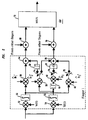
- FIG. 1 depicts a common transmitter architecture 10 in accordance with the present invention.
- Transmitter 10 is typically incorporated at a base station, and is operable to modulate/process user signals employing either orthogonal transmit diversity or space time spreading (using Walsh or some other orthogonal function) techniques.
- Transmitter 10 comprises of a first antenna system 11 and a second antenna system 28.
- the present invention will be described herein with respect to one user signal. It should be understood, however, that the present invention can be applied to multiple user signals.
- Transmitter 10 receives a user signal Y.
- user signal Y is parsed and partitioned into even and odd data bits and then into in-phase and quadrature phase signals, i.e. signal Y is converted into signals Y I1 , Y Q1, Y I2 , and Y Q2 , wherein I represents an in-phase signal, Q represents a quadrature phase signal, 1 represents even data bits and 2 represents odd data bits.
- Signals Y I1 , Y Q1, Y I2 , and Y Q2 are provided as inputs to first and second antenna systems 11 and 28.
- First antenna system 11 comprises time multiplexers 12, inverters 14, switches 16 and 26, amplifiers 18 and 20, mixers 22 and adders 24.
- Switches 16 and 26 have a first position and second position. When switches 16 and 26 are all in the first position, first antenna system 11 operates in orthogonal transmit diversity mode. By contrast, when switches 16 and 26 are all in the second position, first antenna system 11 operates in space time spreading mode.
- Time multiplexer 12-1 is provided twice as input to time multiplexer 12-1.
- the output of time multiplexer 12-1 is a time multiplexed signal of signal Y I1 with itself.
- switch 16-1 When switch 16-1 is in the first position, i.e., OTD mode, the output of time multiplexer 12-1 is directed to amplifier 18-1 where it is amplified a gain G by amplifier 18-1.
- switch 16-1 When switch 16-1 is in the second position, i.e., STS mode, the output of time multiplexer 12-1 is directed to amplifier 20-1 where it is amplified a gain G / ⁇ 2 by amplifier 20-1.
- the outputs of amplifier 18-1 and amplifier 20-1 are mixed at mixer 22-1 with a Walsh function W 1 , and then provided as input to adder 24-1.
- mixer 22-1 should only receive an input from either amplifier 18-1 or 20-1 at any one time, and that some other orthogonal (or quasi-orthogonal) function may be used to mix the output of amplifier 18-1 and 20-1 instead of Walsh functions.
- first antenna system 11 is in STS mode, i.e., switches 16 and 26 are all in the second position, the output of mixer 22-1 is added to an output of mixer 22-3 by adder 24-1 before being transmitted.
- first antenna system 11 is in OTD mode, i.e., switches 16 and 26 are all in the first position, the output of mixer 22-1 is not added to the output of mixer 22-3 by adder 24-1 before being transmitted.
- User signal Y Q1 is processed in a similar manner as user signal Y I1 using time multiplexer 12-2, switch 16-2, amplifiers 18-2 and 20-2, mixer 22-2, adder 24-2 and Walsh function W 1 .
- User signal Y I2 is provided as input to time multiplexer 12-3 along with an inverted signal of Y I2 (i.e. output of inverter 14-1).
- the output of the time multiplexer 12-3 is then provided as input to amplifier 20-3, where it is amplified a gain G / ⁇ 2 .
- the output of amplifier 20-3 is mixed with a Walsh function W 2 by mixer 22-3.
- switch 26-1 When switch 26-1 is in the second position, the output of mixer 22-3 is provided as input to adder 24-1 where it can be added to the output of mixer 22-1.
- the output of mixer 22-3 is not provided as input to adder 24-1.
- first antenna system 11 has a gain of G / ⁇ 2 when it is in STS mode and a gain of G when it is in OTD mode. Such configuration allows for a same output power by first antenna system 11 regardless of the mode. But it should be understood that any configuration of amplifiers and gains may be used. Further note that when first antenna system 11 is in OTD mode, it transmits only even data bits. By contrast, when first antenna system 11 is in STS mode, it transmits both even and odd data bits.
- User signal Y Q2 is processed in a similar manner as signal Y I2 using time multiplexer 12-4, inverter 14-2, amplifier 20-4, mixer 22-4, switch 26-2, adder 24-2 and Walsh function W 2 .
- Second antenna system 28 comprises switches 29, 33 and 40, inverters 30, time multiplexers 32, amplifiers 34 and 36, mixers 38 and adders 42.
- Switches 29, 33 and 40 have a first and second position. When switches 29, 33 and 40 are in the first position, second antenna system 28 operates in OTD mode. By contrast, when switches 29, 33, and 40 are in the second position, second antenna system 28 operates in STS mode.
- switch 29-1 When switch 29-1 is in the first position, user signal Y I2 is provided as input to time multiplexer 32-1 along with an inverted user signal Y I2 (i.e., output of inverter 30-1). When switch 29-1 is in the second position, user signal Y I2 is provided twice as input to time multiplexer 32-1. In time multiplexer 32-1, user signal Y I2 is time multiplexed with itself or its inverted self depending on the position of switch 29-1 (or mode of second antenna system 28).
- time multiplexer 32-1 When switch 33-1 is in the first position, the output of time multiplexer 32-1 is directed to amplifier 34-1, where the time multiplexed signal is amplified a gain G by amplifier 34-1.
- switch 33-1 When switch 33-1 is in the second position, the output of time multiplexer 32-1 is directed to amplifier 36-1, where the time multiplexed signal is amplified a gain G / ⁇ 2 by amplifier 36-1.
- the outputs of amplifiers 34-1 and 36-1 are provided as input to mixer 38-1, where they are mixed with Walsh functions W 3 .
- mixer 38-1 should only receive an input from either amplifier 34-1 or 36-1 at any one time, not both simultaneously. If second antenna system 28 is in STS mode, i.e., switches 29, 33 and 40 are all in the second position, the output of mixer 38-1 is added to an output of mixer 38-3 by adder 42-1 before being transmitted. By contrast, if second antenna system 28 is in OTD mode, i.e., switches 29, 33 and 40 are all in the first position, the output of mixer 38-1 is not added to the output of mixer 38-3 by adder 42-1 before being transmitted.
- User signal Y Q2 is processed in a similar manner to user signal Y I2 using switches 29-2, 33-2 and 40-2, inverter 30-2, time multiplexer 32-2, amplifiers 34-2 and 36-2, mixer 38-2, adder 42-2 and Walsh function W 3 .
- User signal Y I1 is provided as input to time multiplexer 32-3 along with an inverted user signal Y I2 .
- user signal Y I1 is time multiplexed with its inverted self.
- the output of time multiplexer 32-3 is amplified a gain G / ⁇ 2 by amplifier 36-3.
- the output of amplifier 36-3 is mixed in mixer 38-3 with Walsh function W 4 .
- switch 40-1 When switch 40-1 is in the second position, the output of mixer 38-3 is provided as input to adder 42-1 where it is added to the output of mixer 38-1.
- switch 40-1 When switch 40-1 is in the first position, the output of mixer 38-3 is not provided as input to adder 42-1.
- User signal Y Q1 is processed in a similar manner to user signal Y I1 using inverter 30-4, time multiplexer 32-4, amplifier 36-4, mixer 38-4, switch 40-2 and adder 42-2.
- the amplifiers of second antenna system 28 has a gain of G / ⁇ 2 when it is in STS mode and a gain of G when it is in OTD mode.
- Such configuration allows for a same output power by second antenna system 11 regardless of the mode. But it should be understood that any configuration of amplifiers and gains may be used.
- second antenna system 28 when second antenna system 28 is in OTD mode, it transmits only odd data bits.
- second antenna system 28 when second antenna system 28 is in STS mode, it transmits both even and odd data bits.
- Walsh functions W 1 , W 2 , W 3 and W 4 are identical. Note that for ease of discussion, a common receiver architecture is disclosed herein that assumes that Walsh functions W 1 , W 2 , W 3 and W 4 are identical. It should be understood that the different Walsh functions W 1 , W 2 , W 3 and W 4 or combinations thereof may also be used, and that the common receiver architecture disclosed herein could be adapted for different Walsh functions W 1 , W 2 , W 3 and W 4 or combinations thereof.
- FIG. 2 depicts one finger 50 of a common receiver architecture in accordance with the present invention.
- Finger 50 being operable to demodulate/process received signals (transmitted by transmitter 10 or equivalent) employing either orthogonal transmit diversity or space time spreading (using Walsh or some other orthogonal function) techniques.
- Finger 50 comprises mixers 52, 54, 56, 58, 60 and 62, adders 64, 66, 68 and 70, time multiplexer 72, inverters 59, 61 and 63, integrators 53 and 55 and switches 74, 76 and 78.
- Switches 74, 76 and 78 have a first and a second position. When switches 74, 76 and 78 are all in the first position, finger 50 operates in OTD mode. By contrast, when switches 74, 76 and 78 are all in the second position, finger 50 operates in STS mode.
- received signal r(t) is provided as inputs to mixers 52 and 54.
- received signal r(t) is mixed with an extended Walsh function w ( t ), i.e., repeated Walsh function w ( t ).
- the output of mixer 52 is provided as input to integrator 53.
- received signal r(t) is mixed with a function w ( t ), which is a complement of the extended Walsh function w ( t ).
- the output of mixer 54 is provided as input to integrator 55.
- Walsh function w ( t ) is identical to Walsh functions W 1 , W 2 , W 3 and W 4 .
- integrators 53 and 55 the outputs of mixers 52 and 54 are integrated over the length of the Walsh functions w ( t ) or w ( t ) (or symbol rate) and then dumped. Note that the mixers 52 and 54 mixes at a chip rate.
- the output of integrator 53 is provided as inputs to mixers 56 and 62.
- the output of integrator 55 is provided as input to mixer 58, and a conjugate of the output of mixer 54 is provided as input to mixer 60, wherein the conjugate of the output of mixer 54 is obtained by inverting a quadrature stream of the output of mixer 54 using inverter 61.
- mixer 56 the output of mixer 52 is mixed with a signal h ⁇ 1 * representing a conjugate of a channel estimate for first antenna system 11.
- mixer 62 the output of mixer 52 is mixed with a signal h ⁇ 2 * representing a conjugate of a channel estimate for second antenna system 28.
- mixer 58 the output of mixer 54 is mixed with the signal h ⁇ 2 *.
- mixer 60 the conjugate of the output of mixer 54 is mixed with a signal h ⁇ 1 representing a channel estimate for first antenna system 11.
- the channel estimates for first and second antenna systems 11 and 28 are obtained using pilot signals transmitted from first and second antenna systems 11 and 28, respectively.
- the output of mixer 56 is provided as input to adder 64.
- a conjugate of the output of mixer 58 is also provided as input to adder 64 where the conjugate of the output of mixers 58 and the output of mixer 56 are added together. Note that the conjugate of the output of mixer 58 is obtained by inverting a quadrature stream of the output of mixer 58 using inverter 59.
- the output of adder 64 is provided as input to adder 68, where it is added with outputs of same relative mixers from other fingers.
- outputs of adders 68 and 70 are time multiplexed with each other by time multiplexer 72 and directed to a decoder, not shown. Note that in either mode, output of mixer 64 corresponds to a received version of the even data bits and the output of mixer 66 corresponds to a received version of the odd data bits.
- the present invention is described herein with reference to certain embodiments, such as wireless communication systems based on third generation code division multiple access techniques. It should be understood that the present invention may be applicable to wireless communications based on other multiple access techniques. Additionally, instead of even and odd data bits for a same user signal, the present invention may be applied to even and odd data bits for different user signals or some other combinations. The present invention may also be applied to two identical non-partitioned (into odd and even data bits) user signals. Accordingly, the present invention should not be limited to the embodiments disclosed herein.
Landscapes
- Engineering & Computer Science (AREA)
- Computer Networks & Wireless Communication (AREA)
- Signal Processing (AREA)
- Transmitters (AREA)
- Radio Transmission System (AREA)
- Mobile Radio Communication Systems (AREA)
- Time-Division Multiplex Systems (AREA)
Abstract
Description
Claims (19)
- A transmitter comprising:a first time multiplexer for time multiplexing an in-phase first signal with a second in-phase first signal;a first mixer for mixing an output of the first time multiplexer with a first function;a second time multiplexer for time multiplexing a quadrature phase first signal with a second quadrature phase first signal;a second mixer for mixing an output of the second time multiplexer with the first function;a third time multiplexer for time multiplexing an in-phase second signal with an inverted in-phase second signal;a third mixer for mixing an output of the third time multiplexer with a second function;a fourth time multiplexer for time multiplexing a quadrature phase second signal with an inverted quadrature phase second signal;a fourth mixer for mixing an output of the fourth time multiplexer with the second function;a first switch having a first and second position for directing an output of the third mixer,a second switch having a first and second position for directing an output of the fourth mixer,a first adder for adding an output of the first mixer and the output of the third mixer when the first switch is in the second position and not when the first switch is in the first position; anda second adder for adding an output of the second mixer and the output of the fourth mixer when the second switch is in the second position and not when the second switch is in the first position.
- The transmitter of claim 1 wherein the transmitter is in a first operating mode when the first and second switches are in the first position and in a second operating mode when the first and second switches are in the second position, the transmitter further comprising:a fifth time multiplexer for time multiplexing a second in-phase second signal with a second inverted in-phase second signal when the transmitter is in the first operating mode and with a third in-phase second signal when the transmitter is in the second operating mode;a fifth mixer for mixing an output of the fifth time multiplexer with a third function;a sixth time multiplexer for time multiplexing a second quadrature phase second signal with a second inverted quadrature phase second signal when the transmitter is in the first operating mode and with a third quadrature phase second signal when the transmitter is in the second operating mode;a sixth mixer for mixing an output of the sixth time multiplexer with the third function;a seventh time multiplexer for time multiplexing a third in-phase first signal with an inverted in-phase first signal;a seventh mixer for mixing an output of the seventh time multiplexer with a fourth function;an eighth time multiplexer for time multiplexing a third quadrature phase first signal with an inverted quadrature phase first signal;an eighth mixer for mixing an output of the eighth time multiplexer with the fourth function;a third adder for adding an output of the fifth mixer and an output of the seventh mixer when the transmitter is in the second operating mode; anda fourth adder for adding an output of the sixth mixer and an output of the eighth mixer when the transmitter is in the second operating mode.
- The transmitter of claim 2 further comprising:a third switch having a first and second position, wherein the output of the seventh mixer is directed to the third adder when the third switch is in the second position and not directed to the third adder when the third switch is in the first position; anda fourth switch having a first and second position, wherein the output of the eighth mixer is directed to the fourth adder when the fourth switch is in the second position and not directed to the fourth adder when the fourth switch is in the first position.
- The transmitter of claim 2 further comprising:a first inverter for inverting the third in-phase second signal to produce the second inverted in-phase second signal;a second inverter for inverting the third quadrature phase second signal to produce the second inverted quadrature phase second signal;a third switch having a first and second position, wherein the third in-phase second signal is directed to the fifth time multiplexer when the third switch is in the second position and directed to the first inverter when the third switch is in the first position; anda fourth switch having a first and second position, wherein the third quadrature phase second signal is directed to the sixth time multiplexer when the fourth switch is in the second position and directed to the second inverter when the fourth switch is in the first position.
- The transmitter of claim 2 further comprising:a first amplifier for amplifying the output of the fifth multiplexer,a second amplifier for amplifying the output of the sixth time multiplexer,a third amplifier for amplifying the output of the seventh time multiplexer, anda fourth amplifier for amplifying the output of the eighth time multiplexer.
- The transmitter of claim 5, wherein the third amplifier amplifies the output of the seventh time multiplexer by a gain G / √2 , the fourth amplifier amplifies the output of the eighth time multiplexer by a gain G / √2 , the first amplifier comprises a first amplifier A for amplifying the output of the fifth time multiplexer by a gain G and a first amplifier B for amplifying the output of the fifth time multiplexer by a gain G / √2 , and the second amplifier comprises a second amplifier A for amplifying the output of the sixth time multiplexer by a gain 6 and a second amplifier B for amplifying the output of the sixth time multiplexer by a gain G / √2 .
- The transmitter of claim 6 further comprising:a first switch for directing the output of the fifth time multiplexer to the first amplifier A when the transmitter is in the first operating mode and to the first amplifier B when the transmitter is in the second operating mode; anda second switch for directing the output of the sixth time multiplexer to the second amplifier A when the transmitter is in the first operating mode and to the second amplifier B when the transmitter is in the second operating mode.
- A transmitter having a first and a second operating mode comprising:a first time multiplexer for time multiplexing an in-phase first signal with an inverted in-phase first signal when the transmitter is in the first operating mode and with a second in-phase first signal when the transmitter is in the second operating mode;a first mixer for mixing an output of the first time multiplexer with a first function;a second time multiplexer for time multiplexing a quadrature phase first signal with an inverted quadrature phase first signal when the transmitter is in the first operating mode and with a second quadrature phase first signal when the transmitter is in the second operating mode;a second mixer for mixing an output of the second time multiplexer with the first function;a third time multiplexer for time multiplexing an in-phase second signal with an inverted in-phase second signal;a third mixer for mixing an output of the third time multiplexer with a second function;a fourth time multiplexer for time multiplexing a quadrature phase second signal with an inverted quadrature phase second signal;a fourth mixer for mixing an output of the fourth time multiplexer with the second function;a first switch having a first and second position for directing an output of the third mixer;a second switch having a first and second position for directing an output of the fourth mixer;a first adder for adding an output of the first mixer and the output of the third mixer when the first switch is in the second position and not when the first switch is in the first position; anda second adder for adding an output of he second mixer and the output of the fourth mixer when the second switch is in the second position and not when the second switch is in the first position.
- The transmitter of claim 1, 2 or 8, wherein the first and second functions are orthogonal or quasi-orthogonal functions.
- The transmitter of claim 1 or 8, wherein the first and second functions are Walsh functions.
- The transmitter of claim 1 or 8, wherein the first and second functions are different.
- The transmitter of claim 1 or 8, wherein the first and second functions are identical.
- The transmitter of claim 8 further comprising:a first inverter for inverting the second in-phase first signal to produce the inverted in-phase first signal;a second inverter for inverting the second quadrature phase first signal to produce the inverted quadrature phase first signal;a third inverter for inverting a second in-phase second signal to produce the inverted in-phase second signal;a fourth inverter for inverting a second quadrature second signal to produce the inverted quadrature second signal;a third switch having a first and second position for directing the second in-phase first signal, wherein the second in-phase first signal is directed to the first time multiplexer when the third switch is in the second position and directed to the first inverter when the third switch is in the first position; anda fourth switch having a first and second position for directing the second quadrature phase first signal, wherein the second quadrature phase first signal is directed to the second time multiplexer when the fourth switch is in the second position and directed to the second inverter when the fourth switch is in the first position.
- The transmitter of claim 1 or 8 further comprising:a first amplifier for amplifying the output of the first multiplexer,a second amplifier for amplifying the output of the second time multiplexer;a third amplifier for amplifying the output of the third time multiplexer; anda fourth amplifier for amplifying the output of the fourth time multiplexer.
- The transmitter of claim 14 ,wherein the third amplifier amplifies the output of the third time multiplexer by a gain G / √2 , the fourth amplifier amplifies the output of the fourth time multiplexer by a gain G / √2 , the first amplifier comprises a first amplifier A for amplifying the output of the first time multiplexer by a gain G and a first amplifier B for amplifying the output of the first time multiplexer by a gain G / √2 , and the second amplifier comprises a second amplifier A for amplifying the output of the second time multiplexer by a gain G and a second amplifier B for amplifying the output of the second time multiplexer by a gain G / √2 .
- The transmitter of claim 14, when dependent from claim 1, wherein the transmitter is in a first operating mode when the first and second switches are in the first position and in a second operating mode when the first and second switches are in the second position, or the transmitter of claim 14 when dependent from claim 8, further comprising:a third switch for directing the output of the first time multiplexer to the first amplifier A when the transmitter is in the first operating mode and to the first amplifier B when the transmitter is in the second operating mode; anda fourth switch for directing the output of the second time multiplexer to the second amplifier A when the transmitter is in the first operating mode and to the second amplifier B when the transmitter is in the second operating mode.
- The transmitter of claim 1 or 8, wherein the first signal comprises even data bits of a user signal and the second signal comprises odd data bits of the user signal.
- The transmitter of claim 1 or 8, wherein the first and second signals are identical signals.
- The transmitter of claim 1 or 8, wherein the first and second signals are different signals.
Applications Claiming Priority (2)
| Application Number | Priority Date | Filing Date | Title |
|---|---|---|---|
| US09/394,172 US6392988B1 (en) | 1999-09-13 | 1999-09-13 | Transmitter architecture employing space time spreading and orthogonal transmit diversity techniques |
| US394172 | 1999-09-13 |
Publications (2)
| Publication Number | Publication Date |
|---|---|
| EP1087562A2 true EP1087562A2 (en) | 2001-03-28 |
| EP1087562A3 EP1087562A3 (en) | 2003-05-14 |
Family
ID=23557867
Family Applications (1)
| Application Number | Title | Priority Date | Filing Date |
|---|---|---|---|
| EP00307627A Withdrawn EP1087562A3 (en) | 1999-09-13 | 2000-09-04 | A transmitter architecture employing space time spreading and orthogonal transmit diversity techniques |
Country Status (9)
| Country | Link |
|---|---|
| US (1) | US6392988B1 (en) |
| EP (1) | EP1087562A3 (en) |
| JP (1) | JP3930235B2 (en) |
| KR (1) | KR100608427B1 (en) |
| CN (1) | CN1288295A (en) |
| AU (1) | AU5653200A (en) |
| BR (1) | BR0003995A (en) |
| CA (1) | CA2317621C (en) |
| ID (1) | ID27248A (en) |
Cited By (1)
| Publication number | Priority date | Publication date | Assignee | Title |
|---|---|---|---|---|
| EP1282244A1 (en) * | 2001-07-30 | 2003-02-05 | Lucent Technologies Inc. | Symmetric sweep phase sweep transmit diversity |
Families Citing this family (48)
| Publication number | Priority date | Publication date | Assignee | Title |
|---|---|---|---|---|
| US7154958B2 (en) * | 2000-07-05 | 2006-12-26 | Texas Instruments Incorporated | Code division multiple access wireless system with time reversed space time block transmitter diversity |
| US6898441B1 (en) * | 2000-09-12 | 2005-05-24 | Lucent Technologies Inc. | Communication system having a flexible transmit configuration |
| US8249187B2 (en) | 2002-05-09 | 2012-08-21 | Google Inc. | System, method and apparatus for mobile transmit diversity using symmetric phase difference |
| IL158986A0 (en) * | 2001-05-31 | 2004-05-12 | Magnolia Broadband Inc | Communication device with smart antenna using a quality-indication signal |
| US7499709B2 (en) * | 2002-02-07 | 2009-03-03 | Alcatel-Lucent Usa Inc. | Method and apparatus for closed loop transmit diversity in a wireless communications system |
| US7116944B2 (en) * | 2002-02-07 | 2006-10-03 | Lucent Technologies Inc. | Method and apparatus for feedback error detection in a wireless communications systems |
| WO2003081836A1 (en) * | 2002-03-22 | 2003-10-02 | Huawei Technologies Co., Ltd. | A self-adapting weighted space time transmitting diversity method and system thereof |
| WO2004042956A2 (en) * | 2002-11-01 | 2004-05-21 | Magnolia Broadband Inc. | Processing diversity signals using a delay |
| US7418067B1 (en) | 2003-04-14 | 2008-08-26 | Magnolia Broadband Inc. | Processing diversity signals at a mobile device using phase adjustments |
| US7430430B2 (en) * | 2003-12-16 | 2008-09-30 | Magnolia Broadband Inc. | Adjusting a signal at a diversity system |
| US7272359B2 (en) * | 2004-01-26 | 2007-09-18 | Magnolia Broadband Inc. | Communicating signals according to a quality indicator using multiple antenna elements |
| CN100512082C (en) * | 2004-03-12 | 2009-07-08 | 北京交通大学 | Space-time spectrum spreading method for CDMA system |
| US7558591B2 (en) * | 2004-10-12 | 2009-07-07 | Magnolia Broadband Inc. | Determining a power control group boundary of a power control group |
| US7515877B2 (en) * | 2004-11-04 | 2009-04-07 | Magnolia Broadband Inc. | Communicating signals according to a quality indicator and a time boundary indicator |
| US7139328B2 (en) * | 2004-11-04 | 2006-11-21 | Motorola, Inc. | Method and apparatus for closed loop data transmission |
| DE102005017080B4 (en) * | 2005-04-08 | 2007-07-26 | Accelant Communications Gmbh | Transmission method in a radio system with multiple transmission / reception branches in the base station |
| US20060267983A1 (en) * | 2005-05-24 | 2006-11-30 | Magnolia Broadband Inc. | Modifying a signal by adjusting the phase and amplitude of the signal |
| US7616930B2 (en) * | 2005-05-24 | 2009-11-10 | Magnolia Broadband Inc. | Determining a phase adjustment in accordance with power trends |
| US7783267B1 (en) | 2005-06-23 | 2010-08-24 | Magnolia Broadband Inc. | Modifying a signal in response to quality indicator availability |
| US7633905B1 (en) | 2005-09-02 | 2009-12-15 | Magnolia Broadband Inc. | Calibrating a transmit diversity communication device |
| US7835702B1 (en) | 2005-09-15 | 2010-11-16 | Magnolia Broadband Inc. | Calculating a diversity parameter adjustment according to previously applied diversity parameter adjustments |
| US7746946B2 (en) * | 2005-10-10 | 2010-06-29 | Magnolia Broadband Inc. | Performing a scan of diversity parameter differences |
| US7630445B1 (en) | 2005-10-25 | 2009-12-08 | Magnolia Broadband Inc. | Establishing slot boundaries of slots of a diversity control feedback signal |
| US7796717B2 (en) * | 2005-11-02 | 2010-09-14 | Magnolia Brandband Inc. | Modifying a signal according to a diversity parameter adjustment |
| US7965987B2 (en) * | 2005-11-03 | 2011-06-21 | Magnolia Broadband Inc. | Amplifying a transmit signal using a fractional power amplifier |
| KR100807392B1 (en) | 2006-08-30 | 2008-02-28 | 연세대학교 산학협력단 | Digital transmitter for multi-antenna communication system |
| US7949069B2 (en) * | 2006-10-26 | 2011-05-24 | Magnolia Broadband Inc. | Method, system and apparatus for applying hybrid ARQ to the control of transmit diversity |
| US8150441B2 (en) | 2006-11-06 | 2012-04-03 | Magnolia Broadband Inc. | Modifying a signal by controlling transmit diversity parameters |
| US8199735B2 (en) | 2006-12-12 | 2012-06-12 | Google Inc. | Method, system and apparatus for the control of transmit diversity |
| US7663545B2 (en) * | 2006-12-26 | 2010-02-16 | Magnolia Broadband Inc. | Method, system and apparatus for determining antenna weighting for transmit diversity |
| US8027374B2 (en) * | 2006-12-27 | 2011-09-27 | Magnolia Broadband Inc. | Method, system and apparatus for transmit diversity control |
| US20080160990A1 (en) * | 2006-12-29 | 2008-07-03 | Yair Karmi | System, method and apparatus for identification of power control using reverse rate indication |
| US7869535B2 (en) * | 2007-02-28 | 2011-01-11 | Magnolia Broadband Inc. | Method, system and apparatus for phase control of transmit diversity signals |
| US7991365B2 (en) * | 2007-03-01 | 2011-08-02 | Magnolia Broadband Inc. | Method, system and apparatus for estimation of propagation path variability of a transmit diversity channel |
| US20080227414A1 (en) * | 2007-03-01 | 2008-09-18 | Yair Karmi | System, method and apparatus for transmit diversity control based on variations in propagation path |
| US7945222B2 (en) * | 2007-03-14 | 2011-05-17 | Magnolia Broadband Inc. | Method, apparatus and system for providing transmit diversity feedback |
| US8699968B2 (en) | 2007-03-14 | 2014-04-15 | Google Inc. | Using multiple and a single feedback for UE uplink beamforming in soft handoff |
| US8750811B2 (en) * | 2007-03-14 | 2014-06-10 | Google Inc. | Method, apparatus and system for phase difference adjustment in transmit diversity |
| US8032091B2 (en) * | 2007-03-14 | 2011-10-04 | Magnolia Broadband Inc. | Method, apparatus and system for providing transmit diversity feedback during soft handoff |
| US8046017B2 (en) * | 2007-03-15 | 2011-10-25 | Magnolia Broadband Inc. | Method and apparatus for random access channel probe initialization using transmit diversity |
| US8036603B2 (en) * | 2007-03-15 | 2011-10-11 | Magnolia Broadband Inc. | Method, apparatus and system for providing feedback to a transmit diversity device |
| WO2008113038A1 (en) * | 2007-03-15 | 2008-09-18 | Magnolia Broadband Inc. | Method of controlling a transmit diversity device |
| US8032092B2 (en) * | 2007-12-06 | 2011-10-04 | Magnolia Broadband Inc. | System, apparatus and method for introducing antenna pattern variability |
| US8442457B2 (en) | 2009-09-08 | 2013-05-14 | Google Inc. | System and method for adaptive beamforming for specific absorption rate control |
| US8958757B2 (en) | 2010-05-10 | 2015-02-17 | Google Inc. | System, method and apparatus for mobile transmit diversity using symmetric phase difference |
| CN103210696B (en) | 2010-05-26 | 2016-06-08 | 谷歌公司 | Initialized method and apparatus is detected for using transmitting diversity to carry out RACH |
| US9048913B2 (en) | 2010-07-06 | 2015-06-02 | Google Inc. | Method and apparatus for adaptive control of transmit diversity to provide operating power reduction |
| US8849222B2 (en) | 2011-02-16 | 2014-09-30 | Google Inc. | Method and device for phase adjustment based on closed-loop diversity feedback |
Family Cites Families (5)
| Publication number | Priority date | Publication date | Assignee | Title |
|---|---|---|---|---|
| JP2846860B2 (en) * | 1996-10-01 | 1999-01-13 | ユニデン株式会社 | Transmitter, receiver, communication system and communication method using spread spectrum communication system |
| SE9801241L (en) * | 1997-04-09 | 1998-10-10 | Daewoo Telecom Ltd | PC CDMA multibärfrekvenssystem |
| US6173005B1 (en) * | 1997-09-04 | 2001-01-09 | Motorola, Inc. | Apparatus and method for transmitting signals in a communication system |
| US6185266B1 (en) * | 1997-10-07 | 2001-02-06 | Motorola, Inc. | Method and system for generating a power control metric in an orthogonal transmit diversity communication system |
| KR100433901B1 (en) * | 1998-02-21 | 2004-11-06 | 삼성전자주식회사 | Time switching transmit diversity device of a mobile communication system, especially capable of transceiving data with a time switching transmit diversity function |
-
1999
- 1999-09-13 US US09/394,172 patent/US6392988B1/en not_active Expired - Lifetime
-
2000
- 2000-09-04 EP EP00307627A patent/EP1087562A3/en not_active Withdrawn
- 2000-09-05 BR BR0003995-0A patent/BR0003995A/en not_active Application Discontinuation
- 2000-09-06 JP JP2000270156A patent/JP3930235B2/en not_active Expired - Fee Related
- 2000-09-06 CA CA002317621A patent/CA2317621C/en not_active Expired - Fee Related
- 2000-09-06 AU AU56532/00A patent/AU5653200A/en not_active Abandoned
- 2000-09-08 KR KR1020000053298A patent/KR100608427B1/en not_active Expired - Fee Related
- 2000-09-12 CN CN00126392A patent/CN1288295A/en active Pending
- 2000-09-13 ID IDP20000790D patent/ID27248A/en unknown
Cited By (2)
| Publication number | Priority date | Publication date | Assignee | Title |
|---|---|---|---|---|
| EP1282244A1 (en) * | 2001-07-30 | 2003-02-05 | Lucent Technologies Inc. | Symmetric sweep phase sweep transmit diversity |
| US6920314B2 (en) | 2001-07-30 | 2005-07-19 | Lucent Technologies Inc. | Symmetric sweep phase sweep transmit diversity |
Also Published As
| Publication number | Publication date |
|---|---|
| EP1087562A3 (en) | 2003-05-14 |
| ID27248A (en) | 2001-03-15 |
| JP3930235B2 (en) | 2007-06-13 |
| AU5653200A (en) | 2001-03-15 |
| CA2317621A1 (en) | 2001-03-13 |
| BR0003995A (en) | 2001-04-17 |
| KR20010030327A (en) | 2001-04-16 |
| JP2001127674A (en) | 2001-05-11 |
| CA2317621C (en) | 2004-03-23 |
| CN1288295A (en) | 2001-03-21 |
| KR100608427B1 (en) | 2006-08-02 |
| US6392988B1 (en) | 2002-05-21 |
Similar Documents
| Publication | Publication Date | Title |
|---|---|---|
| CA2317621C (en) | A transmitter architecture employing space time spreading and orthogonal transmit diversity techniques | |
| EP1085677A2 (en) | A receiver architecture employing space time spreading and orthogonal transmit diversity techniques | |
| US6980778B2 (en) | Split shift phase sweep transmit diversity | |
| US6920314B2 (en) | Symmetric sweep phase sweep transmit diversity | |
| US7623566B2 (en) | Method and apparatus for demodulating signals processed in a transmit diversity mode | |
| KR960032921A (en) | Data signal transmitting and receiving apparatus and method thereof | |
| IL111449A0 (en) | Method and apparatus for variable rate signal transmission in a spread spectrum communication system using coset coding | |
| EP0430587A2 (en) | Relay communication system | |
| JP3093182B2 (en) | Double orthogonal code jump multiple access communication apparatus and method | |
| US8060132B2 (en) | Apparatus and method for a repeater using a multi-antenna in a wireless communication system | |
| AU9589098A (en) | Polarization enhanced cdma communication system | |
| US20050254445A1 (en) | Receiver and method of operation thereof | |
| US8041326B2 (en) | Data transmission method | |
| US6870825B1 (en) | Pilot signal transmission in a multi-transmit antenna wireless communication system | |
| KR100327640B1 (en) | matched filter simultaneously operating for two different type codes | |
| US7035599B2 (en) | Biased phase sweep transmit diversity | |
| KR20000045004A (en) | Diversity receiver for cdma system | |
| KR20020015086A (en) | Method for orthogonal transmit diversity using differential code in radio communication | |
| KR100382073B1 (en) | Apparatus for multiplex route IF transmission W-CDMA communication system | |
| KR20040000669A (en) | Smart antenna system in a mobile communication network | |
| JPH02253725A (en) | Service channel signal transmission system | |
| CA2495356A1 (en) | Transmitter diversity technique for wireless communications | |
| JPH09205412A (en) | Spread spectrum communication device and spread spectrum communication method | |
| JPH01101032A (en) | System for composing order line |
Legal Events
| Date | Code | Title | Description |
|---|---|---|---|
| PUAI | Public reference made under article 153(3) epc to a published international application that has entered the european phase |
Free format text: ORIGINAL CODE: 0009012 |
|
| AK | Designated contracting states |
Kind code of ref document: A2 Designated state(s): AT BE CH CY DE DK ES FI FR GB GR IE IT LI LU MC NL PT SE |
|
| AX | Request for extension of the european patent |
Free format text: AL;LT;LV;MK;RO;SI |
|
| PUAL | Search report despatched |
Free format text: ORIGINAL CODE: 0009013 |
|
| AK | Designated contracting states |
Designated state(s): AT BE CH CY DE DK ES FI FR GB GR IE IT LI LU MC NL PT SE |
|
| AX | Request for extension of the european patent |
Extension state: AL LT LV MK RO SI |
|
| 17P | Request for examination filed |
Effective date: 20031031 |
|
| 17Q | First examination report despatched |
Effective date: 20031204 |
|
| AKX | Designation fees paid |
Designated state(s): DE FI FR GB SE |
|
| GRAP | Despatch of communication of intention to grant a patent |
Free format text: ORIGINAL CODE: EPIDOSNIGR1 |
|
| STAA | Information on the status of an ep patent application or granted ep patent |
Free format text: STATUS: THE APPLICATION HAS BEEN WITHDRAWN |
|
| 18W | Application withdrawn |
Effective date: 20041004 |