EP1087525A2 - Piezoelectric device - Google Patents
Piezoelectric device Download PDFInfo
- Publication number
- EP1087525A2 EP1087525A2 EP00120019A EP00120019A EP1087525A2 EP 1087525 A2 EP1087525 A2 EP 1087525A2 EP 00120019 A EP00120019 A EP 00120019A EP 00120019 A EP00120019 A EP 00120019A EP 1087525 A2 EP1087525 A2 EP 1087525A2
- Authority
- EP
- European Patent Office
- Prior art keywords
- piezoelectric
- vibration
- piezoelectric device
- electrodes
- vibration electrodes
- Prior art date
- Legal status (The legal status is an assumption and is not a legal conclusion. Google has not performed a legal analysis and makes no representation as to the accuracy of the status listed.)
- Withdrawn
Links
Images




Classifications
-
- H—ELECTRICITY
- H10—SEMICONDUCTOR DEVICES; ELECTRIC SOLID-STATE DEVICES NOT OTHERWISE PROVIDED FOR
- H10N—ELECTRIC SOLID-STATE DEVICES NOT OTHERWISE PROVIDED FOR
- H10N30/00—Piezoelectric or electrostrictive devices
-
- H—ELECTRICITY
- H03—ELECTRONIC CIRCUITRY
- H03H—IMPEDANCE NETWORKS, e.g. RESONANT CIRCUITS; RESONATORS
- H03H9/00—Networks comprising electromechanical or electro-acoustic elements; Electromechanical resonators
- H03H9/15—Constructional features of resonators consisting of piezoelectric or electrostrictive material
- H03H9/17—Constructional features of resonators consisting of piezoelectric or electrostrictive material having a single resonator
- H03H9/177—Constructional features of resonators consisting of piezoelectric or electrostrictive material having a single resonator of the energy-trap type
-
- C—CHEMISTRY; METALLURGY
- C04—CEMENTS; CONCRETE; ARTIFICIAL STONE; CERAMICS; REFRACTORIES
- C04B—LIME, MAGNESIA; SLAG; CEMENTS; COMPOSITIONS THEREOF, e.g. MORTARS, CONCRETE OR LIKE BUILDING MATERIALS; ARTIFICIAL STONE; CERAMICS; REFRACTORIES; TREATMENT OF NATURAL STONE
- C04B35/00—Shaped ceramic products characterised by their composition; Ceramics compositions; Processing powders of inorganic compounds preparatory to the manufacturing of ceramic products
- C04B35/01—Shaped ceramic products characterised by their composition; Ceramics compositions; Processing powders of inorganic compounds preparatory to the manufacturing of ceramic products based on oxide ceramics
- C04B35/46—Shaped ceramic products characterised by their composition; Ceramics compositions; Processing powders of inorganic compounds preparatory to the manufacturing of ceramic products based on oxide ceramics based on titanium oxides or titanates
- C04B35/462—Shaped ceramic products characterised by their composition; Ceramics compositions; Processing powders of inorganic compounds preparatory to the manufacturing of ceramic products based on oxide ceramics based on titanium oxides or titanates based on titanates
- C04B35/475—Shaped ceramic products characterised by their composition; Ceramics compositions; Processing powders of inorganic compounds preparatory to the manufacturing of ceramic products based on oxide ceramics based on titanium oxides or titanates based on titanates based on bismuth titanates
-
- C—CHEMISTRY; METALLURGY
- C04—CEMENTS; CONCRETE; ARTIFICIAL STONE; CERAMICS; REFRACTORIES
- C04B—LIME, MAGNESIA; SLAG; CEMENTS; COMPOSITIONS THEREOF, e.g. MORTARS, CONCRETE OR LIKE BUILDING MATERIALS; ARTIFICIAL STONE; CERAMICS; REFRACTORIES; TREATMENT OF NATURAL STONE
- C04B35/00—Shaped ceramic products characterised by their composition; Ceramics compositions; Processing powders of inorganic compounds preparatory to the manufacturing of ceramic products
- C04B35/01—Shaped ceramic products characterised by their composition; Ceramics compositions; Processing powders of inorganic compounds preparatory to the manufacturing of ceramic products based on oxide ceramics
- C04B35/495—Shaped ceramic products characterised by their composition; Ceramics compositions; Processing powders of inorganic compounds preparatory to the manufacturing of ceramic products based on oxide ceramics based on vanadium, niobium, tantalum, molybdenum or tungsten oxides or solid solutions thereof with other oxides, e.g. vanadates, niobates, tantalates, molybdates or tungstates
-
- H—ELECTRICITY
- H03—ELECTRONIC CIRCUITRY
- H03H—IMPEDANCE NETWORKS, e.g. RESONANT CIRCUITS; RESONATORS
- H03H9/00—Networks comprising electromechanical or electro-acoustic elements; Electromechanical resonators
- H03H9/02—Details
- H03H9/02007—Details of bulk acoustic wave devices
- H03H9/02015—Characteristics of piezoelectric layers, e.g. cutting angles
-
- H—ELECTRICITY
- H03—ELECTRONIC CIRCUITRY
- H03H—IMPEDANCE NETWORKS, e.g. RESONANT CIRCUITS; RESONATORS
- H03H9/00—Networks comprising electromechanical or electro-acoustic elements; Electromechanical resonators
- H03H9/02—Details
- H03H9/02007—Details of bulk acoustic wave devices
- H03H9/02062—Details relating to the vibration mode
- H03H9/0207—Details relating to the vibration mode the vibration mode being harmonic
-
- H—ELECTRICITY
- H03—ELECTRONIC CIRCUITRY
- H03H—IMPEDANCE NETWORKS, e.g. RESONANT CIRCUITS; RESONATORS
- H03H9/00—Networks comprising electromechanical or electro-acoustic elements; Electromechanical resonators
- H03H9/02—Details
- H03H9/02007—Details of bulk acoustic wave devices
- H03H9/02086—Means for compensation or elimination of undesirable effects
- H03H9/02102—Means for compensation or elimination of undesirable effects of temperature influence
-
- H—ELECTRICITY
- H03—ELECTRONIC CIRCUITRY
- H03H—IMPEDANCE NETWORKS, e.g. RESONANT CIRCUITS; RESONATORS
- H03H9/00—Networks comprising electromechanical or electro-acoustic elements; Electromechanical resonators
- H03H9/15—Constructional features of resonators consisting of piezoelectric or electrostrictive material
-
- H—ELECTRICITY
- H10—SEMICONDUCTOR DEVICES; ELECTRIC SOLID-STATE DEVICES NOT OTHERWISE PROVIDED FOR
- H10N—ELECTRIC SOLID-STATE DEVICES NOT OTHERWISE PROVIDED FOR
- H10N30/00—Piezoelectric or electrostrictive devices
- H10N30/80—Constructional details
- H10N30/85—Piezoelectric or electrostrictive active materials
- H10N30/853—Ceramic compositions
-
- C—CHEMISTRY; METALLURGY
- C04—CEMENTS; CONCRETE; ARTIFICIAL STONE; CERAMICS; REFRACTORIES
- C04B—LIME, MAGNESIA; SLAG; CEMENTS; COMPOSITIONS THEREOF, e.g. MORTARS, CONCRETE OR LIKE BUILDING MATERIALS; ARTIFICIAL STONE; CERAMICS; REFRACTORIES; TREATMENT OF NATURAL STONE
- C04B2235/00—Aspects relating to ceramic starting mixtures or sintered ceramic products
- C04B2235/02—Composition of constituents of the starting material or of secondary phases of the final product
- C04B2235/30—Constituents and secondary phases not being of a fibrous nature
- C04B2235/32—Metal oxides, mixed metal oxides, or oxide-forming salts thereof, e.g. carbonates, nitrates, (oxy)hydroxides, chlorides
- C04B2235/3205—Alkaline earth oxides or oxide forming salts thereof, e.g. beryllium oxide
- C04B2235/3208—Calcium oxide or oxide-forming salts thereof, e.g. lime
-
- C—CHEMISTRY; METALLURGY
- C04—CEMENTS; CONCRETE; ARTIFICIAL STONE; CERAMICS; REFRACTORIES
- C04B—LIME, MAGNESIA; SLAG; CEMENTS; COMPOSITIONS THEREOF, e.g. MORTARS, CONCRETE OR LIKE BUILDING MATERIALS; ARTIFICIAL STONE; CERAMICS; REFRACTORIES; TREATMENT OF NATURAL STONE
- C04B2235/00—Aspects relating to ceramic starting mixtures or sintered ceramic products
- C04B2235/02—Composition of constituents of the starting material or of secondary phases of the final product
- C04B2235/30—Constituents and secondary phases not being of a fibrous nature
- C04B2235/32—Metal oxides, mixed metal oxides, or oxide-forming salts thereof, e.g. carbonates, nitrates, (oxy)hydroxides, chlorides
- C04B2235/3205—Alkaline earth oxides or oxide forming salts thereof, e.g. beryllium oxide
- C04B2235/3213—Strontium oxides or oxide-forming salts thereof
-
- C—CHEMISTRY; METALLURGY
- C04—CEMENTS; CONCRETE; ARTIFICIAL STONE; CERAMICS; REFRACTORIES
- C04B—LIME, MAGNESIA; SLAG; CEMENTS; COMPOSITIONS THEREOF, e.g. MORTARS, CONCRETE OR LIKE BUILDING MATERIALS; ARTIFICIAL STONE; CERAMICS; REFRACTORIES; TREATMENT OF NATURAL STONE
- C04B2235/00—Aspects relating to ceramic starting mixtures or sintered ceramic products
- C04B2235/02—Composition of constituents of the starting material or of secondary phases of the final product
- C04B2235/30—Constituents and secondary phases not being of a fibrous nature
- C04B2235/32—Metal oxides, mixed metal oxides, or oxide-forming salts thereof, e.g. carbonates, nitrates, (oxy)hydroxides, chlorides
- C04B2235/3262—Manganese oxides, manganates, rhenium oxides or oxide-forming salts thereof, e.g. MnO
-
- C—CHEMISTRY; METALLURGY
- C04—CEMENTS; CONCRETE; ARTIFICIAL STONE; CERAMICS; REFRACTORIES
- C04B—LIME, MAGNESIA; SLAG; CEMENTS; COMPOSITIONS THEREOF, e.g. MORTARS, CONCRETE OR LIKE BUILDING MATERIALS; ARTIFICIAL STONE; CERAMICS; REFRACTORIES; TREATMENT OF NATURAL STONE
- C04B2235/00—Aspects relating to ceramic starting mixtures or sintered ceramic products
- C04B2235/02—Composition of constituents of the starting material or of secondary phases of the final product
- C04B2235/30—Constituents and secondary phases not being of a fibrous nature
- C04B2235/32—Metal oxides, mixed metal oxides, or oxide-forming salts thereof, e.g. carbonates, nitrates, (oxy)hydroxides, chlorides
- C04B2235/3298—Bismuth oxides, bismuthates or oxide forming salts thereof, e.g. zinc bismuthate
-
- C—CHEMISTRY; METALLURGY
- C04—CEMENTS; CONCRETE; ARTIFICIAL STONE; CERAMICS; REFRACTORIES
- C04B—LIME, MAGNESIA; SLAG; CEMENTS; COMPOSITIONS THEREOF, e.g. MORTARS, CONCRETE OR LIKE BUILDING MATERIALS; ARTIFICIAL STONE; CERAMICS; REFRACTORIES; TREATMENT OF NATURAL STONE
- C04B2235/00—Aspects relating to ceramic starting mixtures or sintered ceramic products
- C04B2235/70—Aspects relating to sintered or melt-casted ceramic products
- C04B2235/74—Physical characteristics
- C04B2235/76—Crystal structural characteristics, e.g. symmetry
Definitions
- the present invention relates to a piezoelectric device, and more particularly to an energy trapping type piezoelectric device operable to use, e.g., a thickness extensional third harmonic vibration.
- the thickness extensional third harmonic vibration has the frequency constant which is about three times larger than that of the fundamental wave. Accordingly, for piezoelectric devices operable to use a fundamental wave, the upper limit of the center frequency is about 15 MHz, considering the restrictions in strength of the piezoelectric substrates. On the other hand, the upper limits in center frequency of piezoelectric device operable to use third harmonic waves are about 30 to 40 MHz. That is, the piezoelectric device can be applied in a higher frequency range.
- the optimum electrode structures are different, depending on material types. Thus, it is necessary to determine the optimum electrode size for each material type.
- the resonant frequency of spurious vibration called an unharmonic overtone
- the unharmonic overtone when the electrode size, namely, the energy trapping range is small, is not excited.
- the maximum in the electrode size range where the unharmonic overtone is not excited depends on material types. Accordingly, it is necessary to determine the maximum electrode size for each material type.
- Unoriented bismuth layer-structure compound type ceramic materials have an excellent thermal stability. Thus, the realization of high performance piezoelectric devices is expectable. However, for the energy trapping piezoelectric devices operable to excite a thickness extensional third harmonic vibration, the maximums in the electrode size ranges where unharmonic overtones are not excited have not been found.
- a piezoelectric device which comprises a piezoelectric substrate comprising a piezoelectric material containing as major components Sr, Bi, Nb, and O, and at least one pair of vibration electrodes formed on both of the faces of the piezoelectric substrate so as to be opposed to each other, being operable to excite a thickness extensional third harmonic wave in the energy trapping range defined by the overlapping electrodes formed on both of the faces of the piezoelectric substrate in opposition to each other, the value L/t being less than 9, in which L represents the maximum distance between the points at which a straight line parallel to the vibration electrodes intersects the outer circumference of the energy-trapping range, and t represents the distance between the vibration electrodes.
- SrBi 2 Nb 2 O 9 is employed as a major component.
- a piezoelectric material containing Sr, Bi, Nb, and O as major components, such as SrBi 2 Nb 2 O 9 is thermally stable. If such a material is used to produce a piezoelectric device operable to excit a thickness extensional third harmonic vibration, and the value L/t is set to be less than 9, superposition of an unharmonic overtone can be avoided, and good energy-trapping can be performed.
- the reference character L represents the diameter of the circle. If the shape is elliptic, L represents the longer axis. If the shape is a rectangle or square, L represents the length of a diagonal line.
- a piezoelectric material containing Ca, Bi, Ti, and O as major components and a piezoelectric material containing Sr, Bi, Ti, and O as major components are be employed.
- Fig. 1 illustrates an example of an piezoelectric device of the present invention.
- Fig. 2 illustrates the side face of the piezoelectric device.
- a piezoelectric device 10 contains a piezoelectric substrate 12.
- the piezoelectric substrate 12 is formed from a piezoelectric ceramic material containing as major components Sr, Bi, Nb, and O.
- As the piezoelectric material for example, a material containing SrBi 2 Nb 2 O 9 as a major component is employed.
- Circular vibration electrodes 14 and 16 are formed substantially in the centers of both of the faces of the piezoelectric substrate 12 so as to be opposed to each other. The vibration electrodes 14 and 16 are led out to the end portions opposed to each other of the piezoelectric substrate 12.
- the vibration electrodes 14 and 16 are formed so as to have a substantially equal diameter.
- the piezoelectric substrate 12 is polarized, e.g., in the direction from the vibration electrode 16 side to the vibration electrode 14 side. Needless to say, the piezoelectric substrate 12 may be polarized in the direction from the vibration electrode 14 side to the vibration electrode 16 side.
- This piezoelectric device 10 is applied as an energy-trapping type piezoelectric device.
- the portion of the piezoelectric device 10 lying between the vibration electrodes 14 and 15 and defined by the overlapping vibration electrodes 14 and 15 constitutes an energy-trapping range.
- the maximum distance L between the points at which a straight line in parallel to the vibration electrodes 14 and 16 intersects the outer circumference of the energy-trapping range namely, the diameter L of the circular portion of each of the vibration electrodes 14 and 16 in the piezoelectric device 10 of Fig. 1, and the distance t between the vibration electrodes 14 and 16 are set in such a manner that the value L/t is less than 9.
- the piezoelectric device 10 formed from a piezoelectric material containing Sr, Bi, Nb, and O as major components such as SrBi 2 Nb 2 O 9 or the like, can be used as a high performance oscillator having a high thermal stability. Further, the piezoelectric device, having the value L/t set at less than 9, can be prevented from exciting an unharmonic overtone.
- SrCO 3 , Bi 2 O 3 , Nb 2 O 5 , and MnCO 3 were prepared. These raw materials were weighed out and mixed in such amounts as to produce a composition of SrBi 2 Nb 2 O 9 + 1 wt.% MnCO 3 .
- the mixed powder was calcined at a temperature of 800 to 1000°C. An appropriate amount of an organic binder was added, and wet-pulverized for four hours by means a ball mill. The grain size was adjusted by passing the powder through a 40 mesh sieve.
- the raw material of which the grain size was adjusted was molded under a pressure of 1000 kg/cm 2 into a rectangular sheet with a size of 30 mm ⁇ 20 mm ⁇ 1.0 mm thick, and fired at a temperature of 1250 to 1300°C for 1 to 5 hours in the atmosphere to produce a porcelain having a rectangular sheet shape.
- the porcelain was cut and polished to form a square sheet of 5 mm ⁇ 5 mm ⁇ 0.4 mm thick.
- the square sheet was polarized in the thickness direction.
- silver electrodes were formed by vapor-deposition on both of the main faces as shown in Fig. 3.
- a piezoelectric device having a structure as shown in Figs. 1 and 2 was formed.
- the thickness of the formed porcelain substrate was 0.4 mm.
- the distance between the vibration electrodes formed on both of the main faces was 0.4 mm.
- the diameter of the energy trapping range that is, the diameter of the circular portion of each of the vibration electrodes was set to be in the range of 1.0 to 5.2 mm.
- Fig. 4 is a graph showing the impedance - frequency characteristic at an electrode diameter of 3.6 mm.
- L is 3.6 mm
- t is 0.4 mm, that is, the value L/t is 9. It is seen that in the piezoelectric device, unharmonic overtones are superposed on the resonant frequencies of the principal vibration.
- Fig. 5 shows the relations of the index L/t to the top-to-bottom ratios (the ratio of the resonant impedance to the anti-resoanct impedance) of the principal vibration and the unharmonic overtones.
- the unharmonic overtone are superposed when the value L/t is 9 or higher.
- the piezoelectric device is used as an oscillator, the unharmonic overtone causes abnormal oscillation, termination of oscillation, and so forth. Further, when the piezoelectric device is used as a filter, the unharmonic overtone causes the problems that the attenuation is decreased, and so forth.
- the piezoelectric device which has at least one pair of energy-trapping vibration electrodes formed on both of the faces of a piezoelectric substrate comprising a material containing as major components Sr, Bi, Nb, and O such as SrBi 2 Nb 2 O 9 , which is a bismuth layer-structure compound type material, in opposition to each other at both of the faces of the piezoelectric substrate, and excites a thickness extensional third harmonic wave, can be used in a high performance piezoelectric resonator with an excellent thermal resistance by setting the size of the electrodes to have the value L/t of less than 9.
- the energy-trapping electrodes have a circular shape.
- the shape may be elliptical, or may be a square, a rectangle, or another polygon.
- L represents the length in a longest portion. That is, in these shapes, the reference character L represents the length of a longest portion, respectively. In an ellipse, L represents the length of the longer axis. In a square or rectangle, L represents the length of a diagonal line.
- the electrodes including the lead-out portions may have a rectangular shape ⁇ as shown in Fig. 6. In this case, the portion of the device defined by the electrodes 14 and 16 overlapped to each other constitutes an energy trapping range.
- the material having a composition containing SrBi 2 Nb 2 O 9 as a major component, to which Mn was added was employed. Further, such materials are available in which at a part of the Sr and Nb positions, other elements are substituted.
- an assisting agent such as a glass component may be added to a composition containing Sr, Bi, Nb, and O as major components.
- the major component of the piezoelectric material used for the piezoelectric device of this example is SrBi 2 Nb 2 O 9 .
- the ratio in number of the elements may be different from the above composition to some degree, provided that the major compound essentially takes the crystal structure of SrBi 2 Nb 2 O 9 , not departing from the scope of the present invention. Also in this case, the advantages of the present invention can be attained.
- the vibration electrodes are formed at both of the faces of the piezoelectric substrate so as to be opposed to each other.
- piezoelectric layers may be formed on the outsides of the vibration electrodes in the thickness direction.
- the vibration electrodes are external electrodes, that is, the electrodes are formed on the outermost parts of the whole of the device without piezoelectric layers provided on the outsides of the electrodes.
- the piezoelectric device is used for an oscillator or a filter, it is necessary to adjust the resonant frequency at a desired value.
- the resonant frequency of the piezoelectric device depends on a piezoelectric material constituting the piezoelectric device, types of the electrodes, the thickness of the device, and so forth.
- a method of applying a coating material or the like to the vibration electrodes, and drying to provide a mass load for the vibration electrodes can be easily applied, when the vibration electrodes are external electrodes and are exposed to the outside of the device.
- a mass load is provided on the vibration electrodes by application of a coating material or the like.
- the vibration electrodes are formed as external electrodes. As described above, if outermost vibration electrodes are external electrodes, a variety of actions on the vibration electrodes can be easily performed.
- a high performance resonator with an excellent thermal resistance can be provided by use of the piezoelectric device of the present invention.
- SrCO 3 , Bi 2 O 3 , TiO 2 , and MnCO 3 were prepared. These raw materials were weighed out and mixed in such amounts as to produce a composition of SrBi 4 Ti 4 O 15 + 1 wt.% MnCO 3 .
- the mixed powder was calcined at a temperature of 800 to 1000°C. Thereafter, an appropriate amount of an organic binder was added, and wet-pulverized for four hours by means of a ball mill. The grain size was adjusted by passing the powder through a 40 mesh sieve.
- the raw material of which the grain size was adjusted was molded under a pressure of 1000 kg/cm 2 into a rectangular sheet with a size of 40 mm ⁇ 25 mm ⁇ 1.2 mm thick, and fired at a temperature of 1150 to 1300°C for 1 to 5 hours in the atmosphere to produce a porcelain having a rectangular sheet shape.
- the porcelain was cut and polished to form a square sheet of 5 mm ⁇ 5 mm ⁇ 0.4 mm thick.
- the square sheet was polarized in thickness direction.
- silver electrodes were formed by vapor-deposition on both of the main faces as shown in Fig. 3.
- a piezoelectric device having a structure as illustrated in Figs. 1 and 2 was formed.
- the diameter of the energy trapping range that is, the diameter of the circular portion of each of the vibration electrodes was set to be in the range of 1.0 to 5.2 mm.
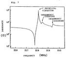
- Fig. 7 is a graph showing the impedance - frequency characteristic at an electrode diameter of 3.6 mm.
- L is 3.6 mm
- t is 0.4 mm, that is, the value L/t is 9. It is seen that in the piezoelectric device, unharmonic overtones are superposed on the resonant frequencies of the principal vibration.
- Fig. 8 shows the relations of the index L/t to the top-to-bottom ratios (the ratio of the resonant impedance to the anti-resonant impedance) of the principal vibration and the unharmonic overtones.
- the unharmonic overtones are superposed when the value L/t is 9 and higher. If the piezoelectric device is used for an oscillator, the unharmonic overtones will cause abnormal oscillation, termination of oscillation, and so forth. Further, if the piezoelectric device is used for a filter, the unharmonic overtones cause the problems that the attenuation is decreased, and so forth.
- the piezoelectric device which has at least one pair of energy-trapping vibration electrodes formed on both of the faces of a piezoelectric substrate comprising a material containing as a major component SrBi 4 Ti 4 O 15 , which is a bismuth layer-structure compound type material, in opposition to each other, and excites a thickness extensional third harmonic wave can be used for a high performance piezoelectric resonator with an excellent thermal resistance by setting the size of the electrodes to have the value L/t of less than 9.
- composition containing SrBi 4 Ti 4 O 15 as a major component, to which Mn was added was used.
- Such materials to which Si and W are added may be employed. Further, such materials are available in which at a part of the Sr and Ti positions, other elements are substituted.
- an assisting agent such as a glass component may be added to the composition containing SrBi 4 Ti 4 O 15 as a major component.
- the major component of the piezoelectric material used for the piezoelectric device of this example includes Sr, Bi, Ti, and O, and is e.g., SrBi 4 Ti 4 O 15 .
- the ratio in number of the elements may be different from the above composition to some degree, provided that the compound substantially takes the crystal structure of SrBi 4 Ti 4 O 15 , not departing from the scope of the present invention. Also in this case, the advantages of the present invention can be attained.
- CaCO 3 , Bi 2 O 3 , TiO 2 , and MnCO 3 were prepared. These raw materials were weighed out and mixed in such amounts as to produce a composition of CaBi 4 Ti 4 O 15 + 1 wt.% MnCO 3 .
- the mixed powder was calcined at a temperature of 800 to 1000°C. Thereafter, an appropriate amount of an organic binder was added, and wet-pulverized for four hours by means of a ball mill. The grain size was adjusted by passing the powder through a 40 mesh sieve.
- the raw material of which the grain size was adjusted was molded under a pressure of 1000 kg/cm 2 into a rectangular sheet with a size of 40 mm ⁇ 30 mm ⁇ 1.0 mm thick, and fired at a temperature of 1100 to 1300°C for 1 to 5 hours in the atmosphere to produce a porcelain having a rectangular sheet shape.
- the porcelain was cut and polished to form a square sheet of 5.5 mm ⁇ 5.5 mm ⁇ 0.4 mm thick.
- the square sheet was polarized in the thickness direction.
- silver electrodes were formed by vapor-deposition on both of the main faces as shown in Fig. 3.
- a piezoelectric device having a structure as illustrated in Figs. 1 and 2 was formed.
- the diameter of the energy trapping range that is, the diameter of the circular portion of each of the vibration electrodes was set to be in the range of 1.0 to 5.2 mm.
- Fig. 9 is a graph showing the impedance - frequency characteristic at an electrode diameter of 3.6 mm.
- L is 3.6 mm
- t is 0.4 mm, that is, the value L/t is 9. It is seen that in the piezoelectric device, the unharmonic overtones are superposed on the resonant frequencies of the principal vibration.
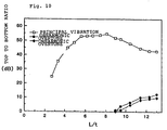
- Fig. 10 shows the relations of the index L/t to the top-to-bottom ratios (the ratio of the resonant impedance to the anti-resonant impedance) of the principal vibration and the unharmonic overtones.
- the unharmonic overtones are superposed when the value L/t is 9 and higher. If the piezoelectric device is used for an oscillator, the unharmonic overtones will cause abnormal oscillation, termination of oscillation, and so forth. Further, if the piezoelectric device is used for a filter, the unharmonic overtones cause the problems that the attenuation is decreased, and so forth.
- the piezoelectric device which has at least one pair of energy-trapping vibration electrodes formed on both of the faces of a piezoelectric substrate comprising a material containing as a major component CaBi 4 Ti 4 O 15 , which is a bismuth layer-structure compound type material, in opposition to each other, and excites a thickness extensional third harmonic wave, can be used for a high performance piezoelectric resonator with an excellent thermal resistance by setting the size of the electrodes to have the value L/t of less than 9.
- compositions containing CaBi 2 Ti 4 O 15 as a major component to which Mn was added, were used. Such materials to which, e.g., Si and W are added may be used. Further, such materials in which at a part of the Ca and Ti positions, other elements are substituted may be employed. Furthermore, such compositions containing CaBi 2 Ti 4 O 15 as a major component, to which an assisting agent such as a glass component is added in order to improve the sintering properties of ceramics, are available.
- the major component of the piezoelectric material used in a piezoelectric device in accordance with the present invention includes Ca, Bi, Ti, and O, and is, e.g., Ca 2 Bi 4 Ti 4 O 15 .
- the ratio in number of the elements may be different from the above composition, provided that the material substantially takes the crystal structure of CaBi 4 Ti 4 O 15 , not departing from the scope of the present invention. In this case, the advantages of the present invention can be also attained.
Landscapes
- Engineering & Computer Science (AREA)
- Chemical & Material Sciences (AREA)
- Ceramic Engineering (AREA)
- Physics & Mathematics (AREA)
- Acoustics & Sound (AREA)
- Manufacturing & Machinery (AREA)
- Materials Engineering (AREA)
- Structural Engineering (AREA)
- Organic Chemistry (AREA)
- Piezo-Electric Or Mechanical Vibrators, Or Delay Or Filter Circuits (AREA)
- Compositions Of Oxide Ceramics (AREA)
Abstract
Description
Claims (6)
- A piezoelectric device comprising a piezoelectric substrate comprising a piezoelectric material containing as major components Sr, Bi, Nb, and O, andat least one pair of vibration electrodes formed on both of the faces of the piezoelectric substrate so as to be opposed to each other,being operable to excite a thickness extensional third harmonic wave in the energy trapping range defined by the overlapping electrodes formed on both of the faces of the piezoelectric substrate in opposition to each other,the value L/t being less than 9, in which L represents the maximum distance between the points at which a straight line parallel to the vibration electrodes intersects the outer circumference of the energy-trapping range, and t represents the distance between the vibration electrodes.
- A piezoelectric device according to claim 1, wherein a major component for the piezoelectric material is SrBi2Nb2O9.
- A piezoelectric device comprising a piezoelectric substrate comprising a piezoelectric material containing as major components Sr, Bi, Ti, and O, andat least one pair of vibration electrodes formed on both of the faces of the piezoelectric substrate so as to be opposed to each other,being operable to excite a thickness extensional third harmonic wave in the energy trapping range defined by the overlapping electrodes formed on both of the faces of the piezoelectric substrate in opposition to each other,the value L/t being less than 9, in which L represents the maximum distance between the points at which a straight line parallel to the vibration electrodes intersects the outer circumference of the energy-trapping range, and t represents the distance between the vibration electrodes.
- A piezoelectric device according to claim 3, wherein a major component for the piezoelectric material is SrBi4Ti4O15.
- A piezoelectric device comprising a piezoelectric substrate comprising a piezoelectric material containing as major components Ca, Bi, Ti, and O, andat least one pair of vibration electrodes formed on both of the faces of the piezoelectric substrate so as to be opposed to each other,being operable to excite a thickness extensional third harmonic wave in the energy trapping range defined by the overlapping electrodes formed on both of the faces of the piezoelectric substrate in opposition to each other,the value L/t being less than 9, in which L represents the maximum distance between the points at which a straight line parallel to the vibration electrodes intersects the outer circumference of the energy-trapping range, and t represents the distance between the vibration electrodes.
- A piezoelectric device according to claim 5, wherein a major component for the piezoelectric material is CaBi4Ti4O15.
Applications Claiming Priority (12)
| Application Number | Priority Date | Filing Date | Title |
|---|---|---|---|
| JP26865199 | 1999-09-22 | ||
| JP26865199 | 1999-09-22 | ||
| JP2000086996 | 2000-03-27 | ||
| JP2000086995 | 2000-03-27 | ||
| JP2000086996 | 2000-03-27 | ||
| JP2000086995 | 2000-03-27 | ||
| JP2000161835 | 2000-05-31 | ||
| JP2000161834 | 2000-05-31 | ||
| JP2000161834A JP2001345668A (en) | 2000-03-27 | 2000-05-31 | Piezoelectric element |
| JP2000161835A JP2001345669A (en) | 2000-03-27 | 2000-05-31 | Piezoelectric element |
| JP2000161833 | 2000-05-31 | ||
| JP2000161833A JP2001160732A (en) | 1999-09-22 | 2000-05-31 | Piezoelectric element |
Publications (2)
| Publication Number | Publication Date |
|---|---|
| EP1087525A2 true EP1087525A2 (en) | 2001-03-28 |
| EP1087525A3 EP1087525A3 (en) | 2008-01-09 |
Family
ID=27554337
Family Applications (1)
| Application Number | Title | Priority Date | Filing Date |
|---|---|---|---|
| EP00120019A Withdrawn EP1087525A3 (en) | 1999-09-22 | 2000-09-14 | Piezoelectric device |
Country Status (3)
| Country | Link |
|---|---|
| US (1) | US6369488B1 (en) |
| EP (1) | EP1087525A3 (en) |
| KR (1) | KR100397136B1 (en) |
Families Citing this family (4)
| Publication number | Priority date | Publication date | Assignee | Title |
|---|---|---|---|---|
| EP1077092A3 (en) * | 1999-08-16 | 2004-03-17 | Murata Manufacturing Co., Ltd. | Piezoelectric element |
| JP3736395B2 (en) * | 2001-07-12 | 2006-01-18 | 株式会社村田製作所 | Piezoelectric element and method for manufacturing piezoelectric element |
| JP2003283291A (en) * | 2002-01-15 | 2003-10-03 | Murata Mfg Co Ltd | Piezoelectric resonator and method of manufacturing the same |
| JP4396136B2 (en) * | 2003-05-21 | 2010-01-13 | 株式会社村田製作所 | Piezoelectric ceramic composition and piezoelectric ceramic element using the same |
Family Cites Families (6)
| Publication number | Priority date | Publication date | Assignee | Title |
|---|---|---|---|---|
| US4833430A (en) * | 1984-11-29 | 1989-05-23 | General Electric Company | Coupled-dual resonator crystal |
| US4676993A (en) * | 1984-11-29 | 1987-06-30 | General Electric Company | Method and apparatus for selectively fine-tuning a coupled-dual resonator crystal and crystal manufactured thereby |
| DE3703241C1 (en) * | 1987-02-04 | 1988-07-14 | Heraeus Gmbh W C | Quartz crystal with temperature-dependent resonance frequency |
| JP2790178B2 (en) * | 1987-06-26 | 1998-08-27 | 株式会社村田製作所 | Electrostrictive resonance device |
| JPH08242026A (en) * | 1995-03-03 | 1996-09-17 | Fujitsu Ltd | Piezoelectric vibrator, piezoelectric vibrator device including the same, and circuit device including the device |
| JPH11100265A (en) * | 1997-09-30 | 1999-04-13 | Hitachi Ltd | Piezoelectric ceramic composition |
-
2000
- 2000-09-14 EP EP00120019A patent/EP1087525A3/en not_active Withdrawn
- 2000-09-21 KR KR10-2000-0055464A patent/KR100397136B1/en not_active Expired - Lifetime
- 2000-09-21 US US09/667,139 patent/US6369488B1/en not_active Expired - Lifetime
Also Published As
| Publication number | Publication date |
|---|---|
| KR100397136B1 (en) | 2003-09-06 |
| KR20010039907A (en) | 2001-05-15 |
| US6369488B1 (en) | 2002-04-09 |
| EP1087525A3 (en) | 2008-01-09 |
Similar Documents
| Publication | Publication Date | Title |
|---|---|---|
| US6383408B1 (en) | Piezoelectric ceramic and surface wave device using the same | |
| US4605876A (en) | Piezoelectric ceramic energy trapping electronic device | |
| JP2000327419A (en) | Piezoelectric porcelain material and piezoelectric porcelain sintered compact obtained by using the material | |
| EP1087525A2 (en) | Piezoelectric device | |
| US6423245B1 (en) | Piezoelectric ceramic composition for surface acoustic wave device and surface acoustic wave device | |
| JP3198613B2 (en) | Surface wave device | |
| US6700303B2 (en) | Piezoelectric element | |
| JP2002167276A (en) | Piezoelectric ceramic composition and piezoresonator | |
| US20080258100A1 (en) | Piezoelectric ceramic composition and resonator | |
| US20030100436A1 (en) | Piezoelectric ceramic composition and piezoelectric element using the same | |
| JP2001158663A (en) | Piezoelectric ceramic composition | |
| JP2003034574A (en) | Piezoelectric ceramic composition and piezoelectric resonator | |
| KR100455218B1 (en) | Piezoelectric ceramic composition and piezoelectric device using the same | |
| JP3646619B2 (en) | Piezoelectric ceramic composition and piezoelectric ceramic element using the same | |
| US6734606B2 (en) | Piezoelectric ceramic composition and piezoelectric ceramic element using the same | |
| JPH07226647A (en) | Piezoelectric resonator and chip-type piezoelectric component using the same | |
| CN1156922C (en) | Pie zoelectrical device | |
| JP2001345669A (en) | Piezoelectric element | |
| JP2001160732A (en) | Piezoelectric element | |
| JP2001345668A (en) | Piezoelectric element | |
| KR100481718B1 (en) | Piezoelectric ceramic composition and piezoelectric device using the same | |
| JP2001127582A (en) | Piezoelectric element | |
| JP2002226265A (en) | Piezoelectric ceramic composition and piezoelectric resonator | |
| JP3618040B2 (en) | Piezoelectric ceramic composition | |
| JP2001127583A (en) | Piezoelectric element |
Legal Events
| Date | Code | Title | Description |
|---|---|---|---|
| PUAI | Public reference made under article 153(3) epc to a published international application that has entered the european phase |
Free format text: ORIGINAL CODE: 0009012 |
|
| 17P | Request for examination filed |
Effective date: 20000914 |
|
| AK | Designated contracting states |
Kind code of ref document: A2 Designated state(s): AT BE CH CY DE DK ES FI FR GB GR IE IT LI LU MC NL PT SE |
|
| AX | Request for extension of the european patent |
Free format text: AL;LT;LV;MK;RO;SI |
|
| RAP1 | Party data changed (applicant data changed or rights of an application transferred) |
Owner name: MURATA MANUFACTURING CO., LTD. |
|
| PUAL | Search report despatched |
Free format text: ORIGINAL CODE: 0009013 |
|
| AK | Designated contracting states |
Kind code of ref document: A3 Designated state(s): AT BE CH CY DE DK ES FI FR GB GR IE IT LI LU MC NL PT SE |
|
| AX | Request for extension of the european patent |
Extension state: AL LT LV MK RO SI |
|
| RIC1 | Information provided on ipc code assigned before grant |
Ipc: H03H 9/02 20060101ALI20071130BHEP Ipc: H01L 41/187 20060101ALI20071130BHEP Ipc: C04B 35/495 20060101ALI20071130BHEP Ipc: C04B 35/46 20060101ALI20071130BHEP Ipc: H03H 9/17 20060101AFI20001222BHEP |
|
| STAA | Information on the status of an ep patent application or granted ep patent |
Free format text: STATUS: THE APPLICATION IS DEEMED TO BE WITHDRAWN |
|
| AKX | Designation fees paid |
Designated state(s): DE FR GB |
|
| 18D | Application deemed to be withdrawn |
Effective date: 20080401 |