EP1087489B1 - Straight joint for cable - Google Patents
Straight joint for cable Download PDFInfo
- Publication number
- EP1087489B1 EP1087489B1 EP00915424A EP00915424A EP1087489B1 EP 1087489 B1 EP1087489 B1 EP 1087489B1 EP 00915424 A EP00915424 A EP 00915424A EP 00915424 A EP00915424 A EP 00915424A EP 1087489 B1 EP1087489 B1 EP 1087489B1
- Authority
- EP
- European Patent Office
- Prior art keywords
- insulating
- flange
- side flanges
- pair
- tubes
- Prior art date
- Legal status (The legal status is an assumption and is not a legal conclusion. Google has not performed a legal analysis and makes no representation as to the accuracy of the status listed.)
- Expired - Lifetime
Links
- 230000002093 peripheral effect Effects 0.000 claims description 21
- 239000004020 conductor Substances 0.000 claims description 10
- 239000011810 insulating material Substances 0.000 claims description 4
- 238000010276 construction Methods 0.000 description 7
- 239000002184 metal Substances 0.000 description 5
- 229910052751 metal Inorganic materials 0.000 description 5
- 229920003002 synthetic resin Polymers 0.000 description 4
- 239000000057 synthetic resin Substances 0.000 description 4
- 238000004078 waterproofing Methods 0.000 description 3
- 239000004593 Epoxy Substances 0.000 description 2
- 238000009413 insulation Methods 0.000 description 2
- 239000012212 insulator Substances 0.000 description 2
- 238000000465 moulding Methods 0.000 description 2
- XLYOFNOQVPJJNP-UHFFFAOYSA-N water Substances O XLYOFNOQVPJJNP-UHFFFAOYSA-N 0.000 description 2
- RYGMFSIKBFXOCR-UHFFFAOYSA-N Copper Chemical compound [Cu] RYGMFSIKBFXOCR-UHFFFAOYSA-N 0.000 description 1
- 229910000881 Cu alloy Inorganic materials 0.000 description 1
- 229910000831 Steel Inorganic materials 0.000 description 1
- 230000015572 biosynthetic process Effects 0.000 description 1
- 229910052802 copper Inorganic materials 0.000 description 1
- 239000010949 copper Substances 0.000 description 1
- 239000013013 elastic material Substances 0.000 description 1
- 238000000034 method Methods 0.000 description 1
- 239000004033 plastic Substances 0.000 description 1
- 229920005989 resin Polymers 0.000 description 1
- 239000011347 resin Substances 0.000 description 1
- 238000007789 sealing Methods 0.000 description 1
- 239000010959 steel Substances 0.000 description 1
- 238000004804 winding Methods 0.000 description 1
Images



Classifications
-
- H—ELECTRICITY
- H02—GENERATION; CONVERSION OR DISTRIBUTION OF ELECTRIC POWER
- H02G—INSTALLATION OF ELECTRIC CABLES OR LINES, OR OF COMBINED OPTICAL AND ELECTRIC CABLES OR LINES
- H02G15/00—Cable fittings
- H02G15/08—Cable junctions
- H02G15/10—Cable junctions protected by boxes, e.g. by distribution, connection or junction boxes
-
- H—ELECTRICITY
- H02—GENERATION; CONVERSION OR DISTRIBUTION OF ELECTRIC POWER
- H02G—INSTALLATION OF ELECTRIC CABLES OR LINES, OR OF COMBINED OPTICAL AND ELECTRIC CABLES OR LINES
- H02G1/00—Methods or apparatus specially adapted for installing, maintaining, repairing or dismantling electric cables or lines
- H02G1/14—Methods or apparatus specially adapted for installing, maintaining, repairing or dismantling electric cables or lines for joining or terminating cables
-
- H—ELECTRICITY
- H02—GENERATION; CONVERSION OR DISTRIBUTION OF ELECTRIC POWER
- H02G—INSTALLATION OF ELECTRIC CABLES OR LINES, OR OF COMBINED OPTICAL AND ELECTRIC CABLES OR LINES
- H02G15/00—Cable fittings
- H02G15/08—Cable junctions
- H02G15/10—Cable junctions protected by boxes, e.g. by distribution, connection or junction boxes
- H02G15/103—Cable junctions protected by boxes, e.g. by distribution, connection or junction boxes with devices for relieving electrical stress
-
- H—ELECTRICITY
- H02—GENERATION; CONVERSION OR DISTRIBUTION OF ELECTRIC POWER
- H02G—INSTALLATION OF ELECTRIC CABLES OR LINES, OR OF COMBINED OPTICAL AND ELECTRIC CABLES OR LINES
- H02G15/00—Cable fittings
- H02G15/08—Cable junctions
- H02G15/10—Cable junctions protected by boxes, e.g. by distribution, connection or junction boxes
- H02G15/103—Cable junctions protected by boxes, e.g. by distribution, connection or junction boxes with devices for relieving electrical stress
- H02G15/105—Cable junctions protected by boxes, e.g. by distribution, connection or junction boxes with devices for relieving electrical stress connected to the cable shield only
-
- H—ELECTRICITY
- H02—GENERATION; CONVERSION OR DISTRIBUTION OF ELECTRIC POWER
- H02G—INSTALLATION OF ELECTRIC CABLES OR LINES, OR OF COMBINED OPTICAL AND ELECTRIC CABLES OR LINES
- H02G15/00—Cable fittings
- H02G15/08—Cable junctions
- H02G15/10—Cable junctions protected by boxes, e.g. by distribution, connection or junction boxes
- H02G15/115—Boxes split perpendicularly to main cable direction
-
- H—ELECTRICITY
- H02—GENERATION; CONVERSION OR DISTRIBUTION OF ELECTRIC POWER
- H02G—INSTALLATION OF ELECTRIC CABLES OR LINES, OR OF COMBINED OPTICAL AND ELECTRIC CABLES OR LINES
- H02G15/00—Cable fittings
- H02G15/08—Cable junctions
- H02G15/18—Cable junctions protected by sleeves, e.g. for communication cable
- H02G15/184—Cable junctions protected by sleeves, e.g. for communication cable with devices for relieving electrical stress
Definitions
- This invention relates to a linear cable-connector, and more particularly to a linear cable-connector which connects the ends of a pair of cables such as electric power cables that supply electric power to various mechanical equipment.
- Fig. 5 shows one example of the conventional linear cable connector that is e.g. presented in that disclosure.
- This linear cable connector 1 has a connection terminal 2 in the center in the middle part of the connector 1 in the axial direction.
- This connection terminal 2 is made of metal such as copper or copper alloy that has good conductivity, and it is formed in a cylindrical shape such that the outer diameter in the middle section is small while the outer diameter at both ends is large, and there are connection holes 3, 3 having a circular cross section and an opening on both ends in the axial direction. It is not shown in the figures, however there is metallic plate with good conductivity formed around the inner peripheral surface of these connection holes 3, 3 to form contact terminals in a well-known structure.
- a pair of cables 4, 4 to be connected have conductors 5, 5, and the portions on the ends of the conductors 5, 5 that are exposed from the insulating coverings 6, 6 of the cables 4, 4 are securely connected to the base ends of plugs 7, 7, and connection tubes 8, 8 are formed on these base ends.
- These plugs 7, 7 are formed in a cylindrical shape from a metal having good conductivity, so by compressing the connection tubes 8, 8 inward in the radial direction after the ends of the aforementioned conductors 5, 5 have been inserted into these connection tubes 8, 8, they are securely fastened to the ends of the conductors 5, 5.
- the tip ends of the plugs 7, 7 are inserted in the respective connection holes 3, 3, and make contact with the connection terminal 2 by way of the aforementioned contact terminals.
- the portion from the end of the insulating coverings 6, 6 to the base end of the plugs 7, 7 is covered by the base half of internal semiconductive layers 9, 9.
- the tip ends of these internal semiconductive layers 9, 9 are cylindrical-shaped sections 10, 10, and there are ring-shaped gaps formed between the inner peripheral surfaces of these cylindrical-shaped sections 10, 10 and the outer peripheral surfaces in the middle of the plugs 7, 7.
- the center component 18 made of an insulating material such as synthetic resin, is formed by molding such that it covers all the way around the circumference of the connection element 2.
- the inner diameter of this center component 18 is small in the middle portion and large on both ends.
- This center component 18 is joined with the aforementioned connection element 2 such that they do not shift each other.
- the outer peripheral surface of this center component 18 is tapered in a direction such that the radius becomes smaller in the direction toward both ends, and the center section has a cylindrical surface.
- a pair of engagement protrusions 11, 11 with trapezoidal cross-sections are formed all the way around the center section such that they are separated from each other in the axial direction.
- insulating layers 12, 12 made of synthetic resin or the like are formed around the ends of the cables 4, 4, around the internal semiconductive layers 9, 9 and around plugs 7, 7, respectively.
- the inner peripheral surface on the tip half of the insulating layers 12, 12, as well as the inner peripheral surface of the cylindrical sections 10, 10 formed on the tip half of the internal semiconductive layers 9, 9 are conical concave tapered surfaces that come in close contact with the outer peripheral surfaces of both ends of the aforementioned center component 18.
- external semiconductive layers 13, 13 made of an elastic material such as rubber are formed around these insulating layers 12, 12. These external semiconductive layers 13, 13, the insulating layers 12, 12 and the internal semiconductive layers 9, 9 come together to form insulating tubes 20, 20.
- the portions that protrude from the tip ends of the insulating layers 12, 12 on the tip ends of the external semiconductive layers 13, 13 are fitting tubes 14, 14.
- Engagement grooves 15, 15 that are formed on the inner peripheral surface of these fitting tubes 14, 14 fit tightly with the aforementioned engagement protrusions 11, 11.
- the outer peripheral surfaces of these fitting tubes 14, 14 are held by retaining bands 16, 16 such that the engagement grooves 15, 15 and the engagement protrusions 11, 11 do not accidentally come apart.
- insulating coverings 17, 17 are formed. It is possible for the formation positions of the engagement grooves 15, 15 and the engagement protrusions 11, 11 to be opposite, as shown in Fig. 6.
- JP 3-54324 U which is considered to represent the most relevant state of the art, discloses a pair of cables connected by a cable connector. Each cable has plug at its end, and both plugs are electrically connected by means of a common connection terminal.
- the connection terminal is surrounded by an insulating centre component, and a pair of insulating tubes are provided which cover the respective ends of the cables and which slide over the centre component to meet in the middle.
- the free end of each insulating tube has a radially inwardly directed lip and both lips are located in position in a common peripheral groove on the outside of the insulating centre component.
- JP 44-11006 Y discloses an outer casing for surrounding cable connections.
- the casing comprises two portions each of which is sealed with a cable entering one side of the connection and the other end being provided with a radially outwardly directed flange.
- the flanges are bolted together either side of a seal to prevent the ingress of water into the connection.
- GB 883,885 discloses a pair of cables connected by a cable connector.
- the conductive portions of the ends of each cable are electrically connected by means of a connection terminal.
- the connection terminal is surrounded by an insulating centre component, and a pair of tubes are provided which cover the respective ends of the cables at one end, and which have a radially outwardly directed flange at the other end.
- the flanges are bolted together and are each provided with a chamfer which extends from the inner surface of the tubes to the point where they meet at the flange to define a peripheral groove in which a corresponding shaped flange of the centre component is located.
- JP 4-47342 U discloses a connector for connecting an oil insulated cable to a rubber or plastic power cable. Conductive portions of the ends of the power cables are electrically connected by a connection terminal. The conductor is surrounded by an embedded metal shield and further by an epoxy insulator. The connector is also provided with a pair of outer tubes, one end of each tube sealing a respective cable and the other end terminating in a radially outwardly extending flange. The outwardly extending flange abuts a common flange which extends radially from the epoxy insulator.
- FR 1,352,064 discloses a pair of cables connected by a cable connector.
- a conductive end portion of each cable is interconnected by means of a connection terminal.
- the connection terminal is surrounded by a centre component with a radially outwardly extending central flange.
- a pair of tubes are provided, one end of each tube covers a respective end of a cable, and the other end of each tube is provided with a radially outwardly extending flange which abuts the central radial flange of the centre component.
- the flange of each tube is bolted to the central radial flange of the centre component and is also provided with a seal.
- GB 883,886 discloses a similar cable connection arrangement to that disclosed in FR 1,352,064 in that outer tubes of the connector are provided with flanges which are bolted to a common peripheral flange of a centre component and which are sealed with a centre component by means of radial seals.
- the objective of this invention is to provide a linear cable connector that is constructed such that it can be disassembled or reconnected easily, and such that it is capable of maintaining stable insulating performance over a long period of time even under severe conditions of use.
- the linear cable connector of this invention comprises: connection terminals that are made of conductive material and formed with connection holes on both ends in the axial direction that open up on both ends; plugs that are made of conductive material and that have tip ends inserted into the aforementioned connection holes, and base ends securely fastened to the ends of conductive members forming a pair of cables to be connected; a center component that is made of insulating material and that is provided all the way around the aforementioned connection terminals such that it covers the connection terminals on the circumference thereof; and a pair of insulating tubes that are provided around the ends of the cables and around the plugs, such that the both ends of the center component can be freely inserted into the openings on the respective ends. Moreover, the opening ends of this pair of insulating tubes are joined together at the middle section of the center component.
- the linear cable connector of this invention comprises side flanges that are formed all the way around the opening ends of the insulating tubes, such that the side flanges of the insulating tubes are fastened together with seal rings located between the abutting flange surfaces, wherein a middle flange is located generally around the outer peripheral surface in the middle of the center component such that it protrudes outward in the radial direction, the middle flange is held between the abutting surfaces of the side flanges on both of the insulating tubes with seal rings interposed, and further, the side flanges on both of the insulating tubes are fastened to the middle flange.
- the linear cable connector of this invention constructed as described above, is effectively sealed with seal rings between both surfaces of the middle side flange and the side surfaces of the side flanges on both of the insulating tubes. Also, disassembly or reconnection can be performed easily by separating or connecting the side flanges on the insulating tubes, or by separating or connecting the surfaces of the middle flange from the side surfaces of both of the side flanges on the insulating tubes.
- Figs. 1 to 3 correspond to Claim 1, and show a first example in the embodiment of the invention.
- the feature of the linear cable connector 1a of this invention is in the construction of the section where the ends of a pair of external semiconductive layers 13a, 13a on the ends of a pair of cables 4, 4 to be connected with each other are connected together with a sufficient seal between them.
- the construction and function of other sections are substantially the same as in the prior art construction shown in Fig. 5, so the same code numbers will be used for identical parts, and any redundant explanation will be omitted. This explanation will center on the features of this invention.
- the center component 18a of the linear cable connector of this invention is made of an insulating material such as synthetic resin, and there is a middle flange 19 formed on the other peripheral surface of its middle section that protrudes outward in the radial direction around its entire circumference.
- insulating-cylinder side flanges 21, 21 that are formed around the opening ends of external semiconductive layers 13a, 13a of the insulating tubes 20a, 20a.
- these insulating-cylinder side flanges 21, 21 are made of a metal such as steel, or from a synthetic resin such as high-functional resin, and they are formed in ring shape having a L-shaped cross section.
- These insulating-tube side flanges 21, 21 are connected and joined to the tip ends of the aforementioned external semiconductive layers 13a, 13a by molding and thermally-connecting (when the insulating-cylinder side flanges are metal) when forming these external semiconductive layers 13a, 13a, or by bonding them with a separately formed object later.
- the contact surface between the insulating-tube side flanges 21, 21 and the external semiconductive layers 13a, 13a is a tight fit all the way around the circumference to form a sure seal.
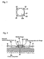
- the shape of the outer peripheral edges of both of the insulating-tube side flanges 21, 21 and the middle flange 19 is square and is such that the corners are curved having a 1/4 circular arc.
- the outer peripheral surfaces of the main portion of the center component 18a, and of the tip ends of the external semiconductive layers 13a, 13a are cylindrical.
- the four corners of both of the insulating-tube side flanges 21, 21 and the middle flange 19 protrude much further outward in the radial direction than the outer peripheral surfaces of the main portion of the center component 18a, and of the tip ends of the external semiconductive layers 13a, 13a.
- both of the insulating-tube side flanges 21, 21 and the middle flange 19 there are through holes formed at the four corners of both of the insulating-tube side flanges 21, 21 and the middle flange 19 such that they are aligned with each other, and bolts 22, 22 pass through these holes. Also, there are nuts 23 that screw onto the tip ends of these bolts 22, 22 in the portion that protrudes from the outside surface of the respective insulating-tube side flanges 21, and by tightening them, both of the insulating-tube side flanges 21, 21 and the middle flange 19 are fastened together.
- attachment grooves 24, 24 formed around the circumference on the opposing surfaces of both of the insulating-tube side flanges 21, 21 in a portion further radially inward than the through holes.
- seal rings that is O-rings 25, 25 that fit inside these attachment grooves 24, 24.
- These O-rings 25, 25 are elastically compressed between both side surfaces of the middle flange 19 and the respective bottom surfaces of the attachment grooves 24, 24 when both of the insulating-tube side flanges 21, 21 and the middle flange 19 are connected and fixed together by the bolts 22, 22 and nuts 23, to form a seal between the abutting surfaces.
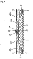
- a center component 18 used does not have a middle flange 19 (see Figs. 1 and 3). Therefore, in this example, the insulating-tube side flanges 21, 21a on the opening ends of the external semiconductive layers 13a, 13a of the insulating tubes 20a, 20a are placed directly together (not by way of a middle flange 19).
- an attachment groove 24 for attaching to the O-ring is formed on only one of the insulating-tube side flanges 21 (left flange in Fig. 4).
- the side surface of the other insulating-tube side flange 21a (right flange in Fig. 4) that faces the aforementioned insulating-tube side flange 21 is a flat surface.
- This pair of insulating-tube side flanges 21, 21a have their abutting surfaces directly come together, and the abutting surfaces are sealed by the O-ring 25.
- This invention is constructed and functions as described above and makes it possible to provide a linear cable connector that is capable of maintaining a sufficient water proofing over a long period of time, even under severe conditions of use such as being placed in locations such as outdoors where it is exposed to wind and rain.
Landscapes
- Cable Accessories (AREA)
- Connector Housings Or Holding Contact Members (AREA)
Description
- This invention relates to a linear cable-connector, and more particularly to a linear cable-connector which connects the ends of a pair of cables such as electric power cables that supply electric power to various mechanical equipment.
- In order to supply electric power to units that are separated by a long distance from the power supply, it is necessary to connect several cables together in series with a connector. Also, when these cables are laid outdoors, it is necessary to adequately maintain the water proofing of the connector for these pairs of cables. A linear cable connector that is used for this purpose has been disclosed, for example, in Japanese Utility Model Registration No. 2579115.
- Fig. 5 shows one example of the conventional linear cable connector that is e.g. presented in that disclosure. This linear cable connector 1 has a
connection terminal 2 in the center in the middle part of the connector 1 in the axial direction. Thisconnection terminal 2 is made of metal such as copper or copper alloy that has good conductivity, and it is formed in a cylindrical shape such that the outer diameter in the middle section is small while the outer diameter at both ends is large, and there areconnection holes connection holes - Moreover, a pair of
cables conductors conductors cables plugs connection tubes plugs connection tubes aforementioned conductors connection tubes conductors plugs respective connection holes connection terminal 2 by way of the aforementioned contact terminals. The portion from the end of the insulating coverings 6, 6 to the base end of theplugs semiconductive layers semiconductive layers shaped sections shaped sections plugs - Moreover, the
center component 18, made of an insulating material such as synthetic resin, is formed by molding such that it covers all the way around the circumference of theconnection element 2. The inner diameter of thiscenter component 18 is small in the middle portion and large on both ends. Thiscenter component 18 is joined with theaforementioned connection element 2 such that they do not shift each other. The outer peripheral surface of thiscenter component 18 is tapered in a direction such that the radius becomes smaller in the direction toward both ends, and the center section has a cylindrical surface. In addition, a pair ofengagement protrusions - Furthermore,
insulating layers cables semiconductive layers plugs insulating layers cylindrical sections semiconductive layers aforementioned center component 18. Also, externalsemiconductive layers insulating layers semiconductive layers insulating layers semiconductive layers insulating tubes - Also, the portions that protrude from the tip ends of the
insulating layers semiconductive layers fitting tubes Engagement grooves fitting tubes aforementioned engagement protrusions fitting tubes bands engagement protrusions semiconductive layers cables insulating coverings engagement grooves engagement protrusions - In the case of the prior art construction described above, disassembly and reconnection are simple, however, water proofing is not always adequate. In other words, when the linear cable connector 1 is installed in a location where it is exposed to wind and rain, rain that enters the connector 1 from the pair of abutting surfaces of the
fitting tubes insulating layers center component 18, and gets inside these insulating layers, 12, 12, and there is a possibility that it will cause poor insulation. - JP 3-54324 U, which is considered to represent the most relevant state of the art, discloses a pair of cables connected by a cable connector. Each cable has plug at its end, and both plugs are electrically connected by means of a common connection terminal. The connection terminal is surrounded by an insulating centre component, and a pair of insulating tubes are provided which cover the respective ends of the cables and which slide over the centre component to meet in the middle. The free end of each insulating tube has a radially inwardly directed lip and both lips are located in position in a common peripheral groove on the outside of the insulating centre component.
- JP 44-11006 Y discloses an outer casing for surrounding cable connections. The casing comprises two portions each of which is sealed with a cable entering one side of the connection and the other end being provided with a radially outwardly directed flange. The flanges are bolted together either side of a seal to prevent the ingress of water into the connection.
- GB 883,885 discloses a pair of cables connected by a cable connector. The conductive portions of the ends of each cable are electrically connected by means of a connection terminal. The connection terminal is surrounded by an insulating centre component, and a pair of tubes are provided which cover the respective ends of the cables at one end, and which have a radially outwardly directed flange at the other end. The flanges are bolted together and are each provided with a chamfer which extends from the inner surface of the tubes to the point where they meet at the flange to define a peripheral groove in which a corresponding shaped flange of the centre component is located.
- JP 4-47342 U discloses a connector for connecting an oil insulated cable to a rubber or plastic power cable. Conductive portions of the ends of the power cables are electrically connected by a connection terminal. The conductor is surrounded by an embedded metal shield and further by an epoxy insulator. The connector is also provided with a pair of outer tubes, one end of each tube sealing a respective cable and the other end terminating in a radially outwardly extending flange. The outwardly extending flange abuts a common flange which extends radially from the epoxy insulator.
- FR 1,352,064 discloses a pair of cables connected by a cable connector. A conductive end portion of each cable is interconnected by means of a connection terminal. The connection terminal is surrounded by a centre component with a radially outwardly extending central flange. A pair of tubes are provided, one end of each tube covers a respective end of a cable, and the other end of each tube is provided with a radially outwardly extending flange which abuts the central radial flange of the centre component. The flange of each tube is bolted to the central radial flange of the centre component and is also provided with a seal.
- GB 883,886 discloses a similar cable connection arrangement to that disclosed in FR 1,352,064 in that outer tubes of the connector are provided with flanges which are bolted to a common peripheral flange of a centre component and which are sealed with a centre component by means of radial seals.
- Taking the above problem into consideration, the objective of this invention is to provide a linear cable connector that is constructed such that it can be disassembled or reconnected easily, and such that it is capable of maintaining stable insulating performance over a long period of time even under severe conditions of use.
- The linear cable connector of this invention comprises: connection terminals that are made of conductive material and formed with connection holes on both ends in the axial direction that open up on both ends; plugs that are made of conductive material and that have tip ends inserted into the aforementioned connection holes, and base ends securely fastened to the ends of conductive members forming a pair of cables to be connected; a center component that is made of insulating material and that is provided all the way around the aforementioned connection terminals such that it covers the connection terminals on the circumference thereof; and a pair of insulating tubes that are provided around the ends of the cables and around the plugs, such that the both ends of the center component can be freely inserted into the openings on the respective ends. Moreover, the opening ends of this pair of insulating tubes are joined together at the middle section of the center component.
- The linear cable connector of this invention comprises side flanges that are formed all the way around the opening ends of the insulating tubes, such that the side flanges of the insulating tubes are fastened together with seal rings located between the abutting flange surfaces, wherein
a middle flange is located generally around the outer peripheral surface in the middle of the center component such that it protrudes outward in the radial direction, the middle flange is held between the abutting surfaces of the side flanges on both of the insulating tubes with seal rings interposed, and further, the side flanges on both of the insulating tubes are fastened to the middle flange. - The linear cable connector of this invention, constructed as described above, is effectively sealed with seal rings between both surfaces of the middle side flange and the side surfaces of the side flanges on both of the insulating tubes. Also, disassembly or reconnection can be performed easily by separating or connecting the side flanges on the insulating tubes, or by separating or connecting the surfaces of the middle flange from the side surfaces of both of the side flanges on the insulating tubes.
-
- Fig. 1 is a cross-sectional drawing of one embodiment of the invention.
- Fig. 2 is an abbreviated side view of Fig. 1.
- Fig. 3 is an enlarged view of the upper half in the middle part of Fig. 1.
- Fig. 4 is a partial cross-sectional view of a linear cable connector not forming part of the invention.
- Fig. 5 is a cross-sectional view of one example of the prior art construction.
- Fig. 6 shows another example of the prior art construction, and is an enlarged view corresponding to the upper half in the middle of Fig. 5.
- The numbers used in the figures represent the following:
- 1, 1a: Linear cable connector, 2: Connection terminal, 3: Connection hole, 4: Cable, 5: Conductor, 6: Insulating covering, 7: Plug, 8: Connection tube, 9: Internal semiconductive layer, 10: Cylindrical-shaped section, 11: Engagement protrusions, 12: Insulating layer, 13,13a: External semiconductive layer, 14: Fitting tubes, 15: Engagement groove, 16: Retaining band, 17: Insulating covering, 18, 18a: Center component, 19: Middle flange, 20, 20a: Insulating tube, 21, 21a: Insulating-tube side flange, 22: Bolt, 23: Nut, 24: Attachment groove, 25: O-ring.
- Figs. 1 to 3 correspond to Claim 1, and show a first example in the embodiment of the invention. The feature of the
linear cable connector 1a of this invention is in the construction of the section where the ends of a pair of externalsemiconductive layers cables - The center component 18a of the linear cable connector of this invention is made of an insulating material such as synthetic resin, and there is a
middle flange 19 formed on the other peripheral surface of its middle section that protrudes outward in the radial direction around its entire circumference. In addition, there are insulating-cylinder side flanges semiconductive layers tubes cylinder side flanges tube side flanges semiconductive layers semiconductive layers tube side flanges semiconductive layers - The shape of the outer peripheral edges of both of the insulating-
tube side flanges middle flange 19 is square and is such that the corners are curved having a 1/4 circular arc. However, the outer peripheral surfaces of the main portion of the center component 18a, and of the tip ends of the externalsemiconductive layers tube side flanges middle flange 19 protrude much further outward in the radial direction than the outer peripheral surfaces of the main portion of the center component 18a, and of the tip ends of the externalsemiconductive layers - There are through holes formed at the four corners of both of the insulating-
tube side flanges middle flange 19 such that they are aligned with each other, andbolts bolts tube side flanges 21, and by tightening them, both of the insulating-tube side flanges middle flange 19 are fastened together. - Moreover, there are
attachment grooves tube side flanges rings attachment grooves rings middle flange 19 and the respective bottom surfaces of theattachment grooves tube side flanges middle flange 19 are connected and fixed together by thebolts nuts 23, to form a seal between the abutting surfaces. - With the linear cable connector of this invention, constructed as described above, a sure seal can be made by the O-ring between the abutting surfaces, specifically between the both side surfaces of the
middle flange 19 and the opposing side surfaces of both of the insulating-tube side flanges bolts nuts 23, and thus it is easy to disassemble or connect themiddle flange 19 and both of the insulating-tube side flanges - In fig. 4 similar to the prior art construction shown in Figs. 5 and 6, a
center component 18 used does not have a middle flange 19 (see Figs. 1 and 3). Therefore, in this example, the insulating-tube side flanges 21, 21a on the opening ends of the externalsemiconductive layers tubes attachment groove 24 for attaching to the O-ring is formed on only one of the insulating-tube side flanges 21 (left flange in Fig. 4). The side surface of the other insulating-tube side flange 21a (right flange in Fig. 4) that faces the aforementioned insulating-tube side flange 21 is a flat surface. - This pair of insulating-
tube side flanges 21, 21a have their abutting surfaces directly come together, and the abutting surfaces are sealed by the O-ring 25. - This invention is constructed and functions as described above and makes it possible to provide a linear cable connector that is capable of maintaining a sufficient water proofing over a long period of time, even under severe conditions of use such as being placed in locations such as outdoors where it is exposed to wind and rain.
Claims (1)
- A linear cable connector (1a) comprising: connection terminals (2) that are made of conductive material and formed with connection holes (3) on both ends in the axial direction that open up on both ends; plugs (7) that are made of conductive material and that have tip ends inserted into the connection holes (3), and base ends securely fastened to the ends of conductive members (5) forming a pair of cables (4) to be connected together; a center component (18a) that is made of insulating material and that is provided all the way around the connection terminals (2) such that it covers the connection terminals (2) on the circumference thereof; and a pair of insulating tubes (20a) that are provided around the ends of the cables (4) and around the plugs (7), such that both ends of the center component (18a) can be freely inserted into the openings on the respective ends, wherein the opening ends of this pair of insulating tubes (20a) are joined together at the middle section of the center component, the linear cable connector (10) characterized by side flanges (21a) that are formed all the way around the opening ends of the insulating tubes (20a), such that the side flanges (21a) are fastened together with seal rings located between the abutting flange surface, wherein a middle flange (19) is located generally around the outer peripheral surface in the middle of the center component (18a) such that it protrudes outward in the radial direction, such that the middle flange (19) is held between the abutting surfaces of the side flanges (21a) on both of the insulating tubes (20a) with seal rings (25) interposed, and that the side flanges (21a) on both of the insulating tubes (20a) are fastened to the middle flange (19).
Applications Claiming Priority (3)
| Application Number | Priority Date | Filing Date | Title |
|---|---|---|---|
| JP10313599 | 1999-04-09 | ||
| JP10313599 | 1999-04-09 | ||
| PCT/JP2000/002283 WO2000062391A1 (en) | 1999-04-09 | 2000-04-07 | Straight joint for cable |
Publications (3)
| Publication Number | Publication Date |
|---|---|
| EP1087489A1 EP1087489A1 (en) | 2001-03-28 |
| EP1087489A4 EP1087489A4 (en) | 2003-08-06 |
| EP1087489B1 true EP1087489B1 (en) | 2006-01-11 |
Family
ID=14346100
Family Applications (1)
| Application Number | Title | Priority Date | Filing Date |
|---|---|---|---|
| EP00915424A Expired - Lifetime EP1087489B1 (en) | 1999-04-09 | 2000-04-07 | Straight joint for cable |
Country Status (5)
| Country | Link |
|---|---|
| US (1) | US6555751B1 (en) |
| EP (1) | EP1087489B1 (en) |
| AU (1) | AU3674100A (en) |
| DE (1) | DE60025473T2 (en) |
| WO (1) | WO2000062391A1 (en) |
Families Citing this family (2)
| Publication number | Priority date | Publication date | Assignee | Title |
|---|---|---|---|---|
| ATE323943T1 (en) * | 2003-07-02 | 2006-05-15 | Abb Research Ltd | POWER TRANSMISSION ELEMENT, METHOD FOR PRODUCING IT AND DEVICE FOR IMPLEMENTING THE METHOD |
| US8808017B2 (en) * | 2013-01-04 | 2014-08-19 | Anderson Power Products, Inc. | Electrical connector with anti-arcing feature |
Family Cites Families (9)
| Publication number | Priority date | Publication date | Assignee | Title |
|---|---|---|---|---|
| GB883885A (en) * | 1959-06-04 | 1961-12-06 | Pirelli | Improvements in or relating to joints or terminals for single-core high-tension fluid-filled electric cables |
| GB883886A (en) * | 1959-06-04 | 1961-12-06 | Pirelli | Improvements in or relating to joints or terminals for single-core high-tension fluid-filled electric cables |
| FR1352064A (en) * | 1963-03-27 | 1964-02-07 | British Insulated Callenders | Improvements at junctions and terminations for cables transmitting electrical energy to fluids |
| JPS4411006Y1 (en) | 1965-07-27 | 1969-05-07 | ||
| JPH0249323U (en) * | 1988-09-30 | 1990-04-05 | ||
| JPH02104727U (en) | 1989-01-31 | 1990-08-21 | ||
| JPH0349323U (en) * | 1989-09-21 | 1991-05-14 | ||
| JP2579115Y2 (en) | 1989-09-28 | 1998-08-20 | 昭和電線電纜株式会社 | Cable connection |
| JPH0447342U (en) | 1990-08-21 | 1992-04-22 |
-
2000
- 2000-04-07 WO PCT/JP2000/002283 patent/WO2000062391A1/en not_active Ceased
- 2000-04-07 DE DE60025473T patent/DE60025473T2/en not_active Expired - Fee Related
- 2000-04-07 US US09/719,248 patent/US6555751B1/en not_active Expired - Fee Related
- 2000-04-07 EP EP00915424A patent/EP1087489B1/en not_active Expired - Lifetime
- 2000-04-07 AU AU36741/00A patent/AU3674100A/en not_active Abandoned
Also Published As
| Publication number | Publication date |
|---|---|
| AU3674100A (en) | 2000-11-14 |
| DE60025473D1 (en) | 2006-04-06 |
| EP1087489A4 (en) | 2003-08-06 |
| WO2000062391A1 (en) | 2000-10-19 |
| US6555751B1 (en) | 2003-04-29 |
| DE60025473T2 (en) | 2008-03-06 |
| EP1087489A1 (en) | 2001-03-28 |
Similar Documents
| Publication | Publication Date | Title |
|---|---|---|
| JP4163957B2 (en) | Cable gland assembly | |
| US3800064A (en) | Universal power cable joint with closed-cell sponge stress relief element | |
| US3567843A (en) | Electrical connector for waterproof jacketed armored cable | |
| JP4680231B2 (en) | connector | |
| US3796821A (en) | High voltage cable termination | |
| US3761602A (en) | Method and connector having conductive elastomeric material encircled by a continuous layer of insulation in intimate contact therewith | |
| US20070015406A1 (en) | Coaxial cable connector with improved weather seal | |
| US20120246920A1 (en) | Split compression mid-span ground clamp | |
| GB2149592A (en) | Cable gland | |
| US4786761A (en) | Gas insulated electrical apparatus | |
| US6555751B1 (en) | Straight joint for cable | |
| US4968857A (en) | Submersible splice and splice cover assembly | |
| US3079580A (en) | Separable connectors for electric conduits and cables | |
| US4859812A (en) | Flat cable and sealing element | |
| US4924038A (en) | Flat cable sealing element | |
| KR101964000B1 (en) | RF coaxial cable connector module | |
| JPH09274947A (en) | Cable junction of equipment direct connection type | |
| JP7635030B2 (en) | Sealed Terminal | |
| CN112331537A (en) | Lightning-protection fuse | |
| JP3673130B2 (en) | Prefab joint | |
| CN216773595U (en) | Open circuit cap adopting IP 66-level sealing mode | |
| EP1089386A1 (en) | Linear cable connection | |
| KR920007518Y1 (en) | Terminal architecture for transformers | |
| WO1997002630A1 (en) | Coupling device | |
| SU1554034A1 (en) | Stick polymeric insulator |
Legal Events
| Date | Code | Title | Description |
|---|---|---|---|
| PUAI | Public reference made under article 153(3) epc to a published international application that has entered the european phase |
Free format text: ORIGINAL CODE: 0009012 |
|
| 17P | Request for examination filed |
Effective date: 20010109 |
|
| AK | Designated contracting states |
Kind code of ref document: A1 Designated state(s): AT BE CH CY DE DK ES FI FR GB GR IE IT LI LU MC NL PT SE |
|
| RIC1 | Information provided on ipc code assigned before grant |
Ipc: 7H 02G 15/105 B Ipc: 7H 02G 15/184 B Ipc: 7H 02G 15/08 A Ipc: 7H 02G 15/103 B Ipc: 7H 02G 1/14 B Ipc: 7H 02G 15/115 B |
|
| A4 | Supplementary search report drawn up and despatched |
Effective date: 20030620 |
|
| 17Q | First examination report despatched |
Effective date: 20040325 |
|
| RBV | Designated contracting states (corrected) |
Designated state(s): DE FR GB IT |
|
| GRAP | Despatch of communication of intention to grant a patent |
Free format text: ORIGINAL CODE: EPIDOSNIGR1 |
|
| GRAS | Grant fee paid |
Free format text: ORIGINAL CODE: EPIDOSNIGR3 |
|
| GRAA | (expected) grant |
Free format text: ORIGINAL CODE: 0009210 |
|
| AK | Designated contracting states |
Kind code of ref document: B1 Designated state(s): DE FR GB IT |
|
| REF | Corresponds to: |
Ref document number: 60025473 Country of ref document: DE Date of ref document: 20060406 Kind code of ref document: P |
|
| ET | Fr: translation filed | ||
| PLBE | No opposition filed within time limit |
Free format text: ORIGINAL CODE: 0009261 |
|
| STAA | Information on the status of an ep patent application or granted ep patent |
Free format text: STATUS: NO OPPOSITION FILED WITHIN TIME LIMIT |
|
| 26N | No opposition filed |
Effective date: 20061012 |
|
| PGFP | Annual fee paid to national office [announced via postgrant information from national office to epo] |
Ref country code: DE Payment date: 20070405 Year of fee payment: 8 |
|
| REG | Reference to a national code |
Ref country code: DE Ref legal event code: 8581 |
|
| PGFP | Annual fee paid to national office [announced via postgrant information from national office to epo] |
Ref country code: GB Payment date: 20070404 Year of fee payment: 8 |
|
| PGFP | Annual fee paid to national office [announced via postgrant information from national office to epo] |
Ref country code: IT Payment date: 20070518 Year of fee payment: 8 |
|
| PGFP | Annual fee paid to national office [announced via postgrant information from national office to epo] |
Ref country code: FR Payment date: 20070411 Year of fee payment: 8 |
|
| GBPC | Gb: european patent ceased through non-payment of renewal fee |
Effective date: 20080407 |
|
| PG25 | Lapsed in a contracting state [announced via postgrant information from national office to epo] |
Ref country code: DE Free format text: LAPSE BECAUSE OF NON-PAYMENT OF DUE FEES Effective date: 20081101 |
|
| REG | Reference to a national code |
Ref country code: FR Ref legal event code: ST Effective date: 20081231 |
|
| PG25 | Lapsed in a contracting state [announced via postgrant information from national office to epo] |
Ref country code: FR Free format text: LAPSE BECAUSE OF NON-PAYMENT OF DUE FEES Effective date: 20080430 |
|
| PG25 | Lapsed in a contracting state [announced via postgrant information from national office to epo] |
Ref country code: GB Free format text: LAPSE BECAUSE OF NON-PAYMENT OF DUE FEES Effective date: 20080407 |
|
| PG25 | Lapsed in a contracting state [announced via postgrant information from national office to epo] |
Ref country code: IT Free format text: LAPSE BECAUSE OF NON-PAYMENT OF DUE FEES Effective date: 20080407 |