EP1087470B1 - Ein Verbinder - Google Patents
Ein Verbinder Download PDFInfo
- Publication number
- EP1087470B1 EP1087470B1 EP00120583A EP00120583A EP1087470B1 EP 1087470 B1 EP1087470 B1 EP 1087470B1 EP 00120583 A EP00120583 A EP 00120583A EP 00120583 A EP00120583 A EP 00120583A EP 1087470 B1 EP1087470 B1 EP 1087470B1
- Authority
- EP
- European Patent Office
- Prior art keywords
- slider
- displacement
- lock arm
- connector housing
- forcible
- Prior art date
- Legal status (The legal status is an assumption and is not a legal conclusion. Google has not performed a legal analysis and makes no representation as to the accuracy of the status listed.)
- Expired - Lifetime
Links
Images


Classifications
-
- H—ELECTRICITY
- H01—ELECTRIC ELEMENTS
- H01R—ELECTRICALLY-CONDUCTIVE CONNECTIONS; STRUCTURAL ASSOCIATIONS OF A PLURALITY OF MUTUALLY-INSULATED ELECTRICAL CONNECTING ELEMENTS; COUPLING DEVICES; CURRENT COLLECTORS
- H01R13/00—Details of coupling devices of the kinds covered by groups H01R12/70 or H01R24/00 - H01R33/00
- H01R13/62—Means for facilitating engagement or disengagement of coupling parts or for holding them in engagement
- H01R13/629—Additional means for facilitating engagement or disengagement of coupling parts, e.g. aligning or guiding means, levers, gas pressure electrical locking indicators, manufacturing tolerances
-
- H—ELECTRICITY
- H01—ELECTRIC ELEMENTS
- H01R—ELECTRICALLY-CONDUCTIVE CONNECTIONS; STRUCTURAL ASSOCIATIONS OF A PLURALITY OF MUTUALLY-INSULATED ELECTRICAL CONNECTING ELEMENTS; COUPLING DEVICES; CURRENT COLLECTORS
- H01R13/00—Details of coupling devices of the kinds covered by groups H01R12/70 or H01R24/00 - H01R33/00
- H01R13/66—Structural association with built-in electrical component
- H01R13/70—Structural association with built-in electrical component with built-in switch
- H01R13/703—Structural association with built-in electrical component with built-in switch operated by engagement or disengagement of coupling parts, e.g. dual-continuity coupling part
- H01R13/7031—Shorting, shunting or bussing of different terminals interrupted or effected on engagement of coupling part, e.g. for ESD protection, line continuity
- H01R13/7032—Shorting, shunting or bussing of different terminals interrupted or effected on engagement of coupling part, e.g. for ESD protection, line continuity making use of a separate bridging element directly cooperating with the terminals
Definitions
- the present invention relates to a connector.
- FIGS. 11(A) and 11(B) comprised of a male connector housing 101 and a female connector housing 102.
- a lock arm 103 for locking the female connector housing 102 and a slider 104 for holding the lock arm 103 in such a position where it can lock the female connector housing 102 are provided in the male connector housing 101.
- the slider 104 is provided with compression coil springs (not shown) for accumulating biasing forces which act in a direction to separate the female connector housing 102 from the male connector housing 101 as the female connector housing 102 is fitted into the male connector housing 101.
- the lock arm 103 concealed inside in order to make it difficult to disengage the lock arm 103 from outside has not only a locking function, but also an unlocking function.
- the locking surface 103A of the lock arm 103 to be engaged with the female connector housing 102 is formed to be slightly oblique with respect to a direction normal to a disengaging direction of the female connector housing 102.
- US-A-5 803 651 discloses a double locking connector with an engagement detecting member disposed slidably on an operating section of a flexible locking arm of a connector housing. An operating plate section of the engagement detection member overlaps a front end section of a mating connector housing in a state of the flexible detection arm being locked, thus preventing the connector from being inadvertently unlocked.
- EP-A-1 049 213 which is prior art under Article 54(3) EPC, discloses a connector comprising a pair of connector housings connectable with each other, one connector housing comprising:
- the present invention was developed in view of the above problem, and an object thereof is to secure the reliability of a locking function of a lock arm.
- a connector comprising a pair of connector housings connectable with each other, one connector housing comprising:
- the forcible displacing means When the slider is moved from the displacement restricting position to the displacement permitting position with the connector housings fitted with each other, the forcible displacing means forcibly displaces the lock arm to the unlocking position. Since it is not necessary to provide a locking portion of the lock arm and the other connector housing with an unlocking function, reliability of a locking function by the lock arm can be improved.
- the forcible displacement position is located at the substantially opposite side from the displacement restricting position with respect to the displacement permitting position.
- the forcible displacing means forcibly displaces the lock arm with the restriction on the displacement of the lock arm by the slider released, the forcibly displacing operation can be performed with high reliability.
- the forcible displacing means comprises a pushing portion formed on the slider and a pushable portion formed on the lock arm, at least one of the pushing portion and the pushable portion being preferably formed with a slanted surface inclined with respect to both moving directions of the slider and displacing directions of the lock arm.
- the forcible displacing means displaces the lock arm to the unlocking position taking advantage of the inclination of the slanted surface, the construction can be simplified.
- the restriction on the movement of the slider toward the displacement restricting position by the holding means is released by means of slanted surfaces formed at the holding means and the other connector housing coming into contact with each other as the one connector housing is properly connected with the other connector housing.
- the two connector housings are locked into each other by the lock arm, and the restriction on the movement of the slider by the holding means is released and, thus, the slider is moved to the displacement restricting position by the biasing force of the biasing means.
- the connector housings are automatically locked into each other upon being properly connected with each other, saving a manual operation.
- the biasing means accumulates a biasing force to separate the other connector housing by being elastically deformed by the other connector housing being connected.
- the other connector housing is forcibly displaced in a separating direction by the biasing force accumulated in the biasing means if the connecting operation is interrupted halfway, a partial connection can be prevented.
- the number of parts can be reduced since the biasing means for biasing the slider from the forcible displacement position to the displacement permitting position is additionally provided with a partial connection preventing function.
- the slider comprises a shorting terminal for shorting terminal fittings provided in the one connector housing.
- the shorting terminal shorts the terminal fittings when the slider is in the displacement permitting portion and/or the forcible displacement position, whereas the shorted state of the terminal fittings is released when the slider is in the displacement restricting portion.
- FIGS. 1 to 10 a preferred embodiment of the invention is described with reference to FIGS. 1 to 10 .
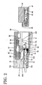
- a connector according to this embodiment is comprised of a male connector housing 10 including male terminal fittings 13, a slider 20 and a shorting terminal 35, and a female connector housing 40 including female terminal fittings 42.
- the connector housings 10, 40 are connectable with and separable from each other.
- surfaces of the respective connector housings 10, 40 facing the mating connector housings 40, 10 are referred to as front surfaces, and vertical direction is based on FIGS. 1 to 6 .
- the female connector housing 40 (as an other connector housing) is described.
- a plurality of cavities 41 are arranged substantially side by side in the female connector housing 40, and the female terminal fittings 42 are at least partly inserted into the respective cavities 41.
- a locking surface or portion 43 which is slightly inclined with respect to a direction normal to a connecting direction of the housings 10, 40 (hereinafter, merely "connecting direction") is formed. It should be noted that an angle and a direction of the inclination of the locking surface 43 are substantially the same as those of a rear surface 17R of a locking projection 17A of a lock arm 17.
- a pair of pushing portions 44 in the form of ribs extend substantially in parallel to the connecting direction at the opposite sides of the locking surface 43.
- a slanted or inclined guide surface 45 which descends to the front is formed at the front end of the upper surface of the female connector housing 40.
- a receptacle 11 which is open forward is formed in a front and lower half of the male connector housing 10, and the female connector housing 40 is at least partly fitted or inserted into the receptacle 11.
- a plurality of cavities 12 having a lower height than the receptacle 11 are formed substantially side by side behind the receptacle 11, and the male terminal fittings 13 connectable with the female terminal fittings 42 are at least partly inserted in the respective cavities 12.
- An accommodation space 14 which is open in the rear surface of and a rear half of the upper surface of the male connector housing 10 is formed in an area of the male connector housing 10 above the receptacle 11 and the cavities 12.
- a front half of the accommodation space 14 substantially communicates with the receptacle 11, and a rear half is partitioned from the cavities 12 by upper walls 12A.
- Guide grooves 15 extending in forward and backward directions and each formed at its rear end with a stopper 15A are formed in the left and right inner wall surfaces of the accommodation space 14.
- a pair of left and right escape grooves 16 for at least partly receiving the pushing portions 44 of the female connector housing 40 into the accommodation space 14 are formed at the front end of the accommodation space 14.
- the lock arm 17 cantilevers forward along the boundary between the accommodation space 14 and the receptacle 11.
- the lock arm 17 is usually in a locking position as shown in FIGS. 1 , 4 and 5 .
- the lock arm 17 is substantially elastically displaced to an unlocking position as shown in FIGS. 3 and 6 which is located above the locking position.
- the lock arm 17 is elastically returned substantially to the locking position when being released from the external force in the unlocking position.
- the front end of the lock arm 17 is preferably located substantially in a middle position of the receptacle 11 with respect to forward and backward directions, and a locking projection 17A engageable with the locking surface 43 projects down (toward the receptacle 11) therefrom.
- the rear surface 17R of the locking projection 17A is slightly inclined with respect to the direction normal to the connecting direction of the connector housings 10, 40, such that it obliquely extends to the back from its upper end to its bottom end. Accordingly, the locking projection 17A is locked with its bottom end portion held substantially in contact with the locking surface 43. Even if a force acts in a direction to separate the connector housings 10, 40 in this locked state, the locking projection 17A is not displaced upward (direction to disengage from the locking surface 43), with the result that secure locking can be ensured.
- a slanted or inclined guide surface 17F for coming into contact with the slanted guide surface 45 of the female connector housing 40 during the connection of the connector housings 10, 40 is formed on the front surface of the locking projection 17A.
- a pushable portion 18 which forms a forcible displacing means for forcibly displacing the lock arm 17 to its unlocking position by the slider 20 is formed at the front end of the lock arm 17.
- the pushable portion 18 projects upward from the upper surface of the lock arm 17 and projects sideways from the left and right side surfaces of the lock arm 17, and a slanted or inclined surface 18A is formed at the rear surface of the pushable portion 18.
- the slanted surface 18A is inclined with respect to both the forward and backward moving directions of the slider 20 and the vertical displacing directions of the lock arm 17, such that it obliquely extends to the back from the bottom end to the upper end. Accordingly, when a forward acting pushing force is exerted on the slanted surface 18A from behind, an upward (toward the unlocking position) pushing force acts on the lock arm 17.
- the slider 20 has a function of forcibly displacing the lock arm 17 to the unlocking position in addition to a function of restricting and permitting the displacement of the lock arm 17 between the locking position and the unlocking position.
- the slider 20 is movable in forward and backward directions in the accommodation space 14 by at least partly fitting or inserting its guidable portions (not shown) on the left and right side surfaces into the guide grooves 15.
- a position located at the rear end of a moving path of the slider 20 where any further backward movement of the slider 20 is restricted by the guidable portions coming into contact with the stoppers 15A is referred to as a displacement restricting position, whereas a position (see FIG.
- a forcible displacement position located at the front end of the moving path of the slider 20 where a forward movement of the slider 20 is stopped by the slider 20 coming into contact with a front wall 14F of the accommodation space 14 is referred to as a forcible displacement position. Further, a position (see FIGS. 1 to 4 ) slightly backward from the forcible displacement position is referred to as a displacement permitting position.
- a displacement restricting surface or portion 21 is formed preferably at the front end of a middle part of the lower surface of the slider 20 with respect to widthwise direction.
- the slider 20 comes into contact with the upper surface of the pushable portion 18 of the lock arm 17 in its locking position, thereby restricting the displacement of the lock arm 17 to the unlocking position (see FIG. 5 ).
- Behind the displacement restricting surface 21 in the slider 20 is defined a deformation permitting space 22 open downward (side to face the lock arm 17).
- a backward movement restricting surface or portion 23 preferably substantially continuous with the rear end of the displacement restricting surface 21 is formed at the front end of the deformation permitting space 22.
- the slider 20 is formed with a pair of left and right pushing portions 24 as the forcible displacing means which project inwardly from the bottom ends of the left and right inner side surfaces of the deformation permitting space 22.
- the pushing portions 24 are elongated in forward and backward directions (moving directions of the slider 20), and are provided in such positions retracted sideways from a displacement area of the lock arm 17 in order to avoid interference with the lock arm 17 displacing to the unlocking position.
- Such pushing portions 24 are transversely so positions as to overlap or correspond to portions of the pushable portion 18 of the lock arm 17 projecting to the left and the right, and vertically positioned at the same height as the pushable portion 18 when the lock arm 17 is in the locking position.
- a slanted or inclined surface 24A inclined backward with respect to the moving directions of the slider 20 (so as to obliquely descend to the front) is formed at the surface of each pushing portion 24.
- An angle of inclination of the slanted surfaces 24A is set at the substantially same as the slanted surface 18A of the pushable portion 18 when the lock arm 17 is in the locking position.
- the slanted surfaces 24A of the slider 20 are largely distanced from the slanted surface 18A of the lock arm 17.
- the slanted surfaces 24A and 18A are opposed to each other substantially in contact when the slider 20 is in the displacement permitting position and the lock arm 17 is in the unlocking position (see FIGS. 1 and 4 ).
- the lock arm 17 is forcibly pushed up from the locking position to the unlocking position while the slanted surface 18A is sliding in contact with the slanted surfaces 24A of the slider 20 by the engaging action of the slanted surfaces 18A and 24A.
- a pair of spring chambers 25 are formed at the opposite sides of the deformation permitting space 22 in the slider 20, and compression coil springs 26 (biasing means) whose longitudinal axes extend in forward and backward directions (the same directions as the moving directions of the slider 20) are at least partly accommodated in the spring chambers 25.
- Spring washers 27 having a flat front surface are mounted at the front ends of the compression coil springs 26 and, on the other hand, spring contact portions 28 project backward from the front wall 14F of the accommodation space 14 and receiving grooves 29 for permitting the upper front ends of the pushing portions 44 of the female connector housing 40 into the spring chambers 25 are formed in the front wall of the spring chambers 25.
- a pair of left and right elastic holding pieces 30 (holding means as a feature of the invention) in the form of cantilevers projecting forward (toward the female connector housing 40 being connected) are formed on the bottom surface of the slider 20.
- the elastic holding pieces 30 are elastically displaceable upward, and a holding projection 31 which extends in a direction substantially normal to the moving directions of the slider 20 is formed on the lower surface of each holding projection 30.
- the holding projections 31 are or can be engaged with receiving portions 32 at the upper edge of the rear end surface of the receptacle 11 by the elastic restoring forces of the elastic holding pieces 30 to effect locking.
- the slider 20 is held in the displacement permitting position while its backward movement is restricted against the biasing forces of the compression coil springs 26 acting toward the displacement restricting position.
- slanted surfaces 33 are formed at the lower surfaces of front end portions of the elastic holding pieces 30. With the holding projections 31 engaged with the receiving portions 32, the slanted surfaces 33 come into contact with the slanted guide surfaces 45 of the female connector housing 40 substantially at the same time the connector housings 10, 40 are properly connected, and the elastic holding pieces 30 are disengaged from the receiving portions 32 while moving onto the slanted guide surface 45. As a result, the function of the elastic holding pieces 30 to hold the slider 20 is canceled.
- the compression coil springs 26 of the slider 20 also function as a partial connection preventing means in cooperation with the pushing portions 44 of the female connector housing 40. Specifically, during the connection of the connector housings 10, 40, the front ends of the pushing portions 44 enter the spring chambers 25 of the slider 20 in the displacement permitting position, and elastically compress the compression coil springs 26 as the connection progresses. In other words, the compression coil springs 26 accumulate the biasing forces in the direction to separate the female connector housing 40 (in the direction to push the female connector housing 40 out of the receptacle 11) by being elastically compressed by the female connector housing 40 being connected.
- a base end 35A of the shorting terminal 35 made e.g. of an electrically conductive plate member is integrally or unitarily movably mounted on a rear part of the bottom surface of the slider 20.
- the shorting terminal 35 is formed with a plurality of contact pieces 35B which extend forward from the rear end of the base end 35A and substantially correspond to the respective cavities 12. Projecting ends of the contact pieces 35B serve as contact portions 35C with the male terminal fittings 13.
- the contact portions 35C of the shorting terminal 35 are elastically held in contact with the upper surface of the male terminal fittings 13 through rectangular holes 36 formed in the upper walls 12A of the cavities 12 (see FIGS. 1 to 4 and 6 ).
- the male terminal fittings 13 are shorted or connected with each other via the shorting terminal 35.
- the contact portions 35C are moved away from the rectangular holes 36 to be brought into contact with the upper surface of the upper walls 12A of the cavities 12 (see FIG. 5 ).
- the shorted state of the male terminal fittings 13 is released.
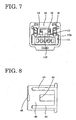
- the slider 20 Prior to the connection of the connector housings 10, 40, the slider 20 is first held in the displacement permitting position in the male connector housing 10 (see FIGS. 1 and 2 ). At this time, the slider 20 is biased backward by the compression coil springs 26 and has its backward movement restricted by the elastic holding pieces 30. If the female connector housing 40 is fitted or inserted into the receptacle 11 in this state, the lock arm 17 is displaced to the unlocking position while moving onto the upper surface of the female connector housing 40 and the compression coil springs 26 are elastically compressed by the pushing portions 44, with the result that a force to separate the female connector housing 40 from the male connector housing 10 is given to the female connector housing 40 (see FIG. 8 ).
- the female connector housing 40 is pushed out of the receptacle 11 by the biasing forces of the compression coil springs 26. This prevents the connector housings 10, 40 from being held partly connected.
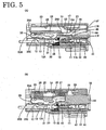
- the lock arm 17 is elastically returned to the locking position to engage the locking projection 17A with the locking surface 43 of the female connector housing 40, with the result that the connector housings 10, 40 are locked into each other (see FIG. 4 ).
- the elastic holding pieces 30 are elastically displaced to disengage from the receiving portions 32 while moving onto the slanted guide surface 45 of the female connector housing 40, and the restriction on the backward direction of the slider 20 by the elastic holding pieces 30 is released.
- the slider 20 is moved backward from the displacement permitting position to the displacement restricting position by the biasing forces of the compression coil springs 26 (see FIG. 5 ). Unless the lock arm 17 is completely returned to the locking position even if the holding function of the elastic holding pieces 30 is released, the backward movement restricting surface 23 of the slider 20 interferes the pushable portion 18 of the lock arm 17. Accordingly, the slider 20 remains in the displacement permitting position.
- the displacement restricting surface 21 is brought into contact with the upper surface of the pushable portion 18 so as to press the pushable portion 18 from above.
- the upward displacement of the lock arm 17 toward the unlocking position is restricted to secure the locked state of the locking projection 17A and the locking surface 43. In this way, the connector housings 10, 40 are locked in the properly connected state, thereby completing the connecting operation.
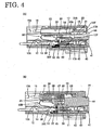
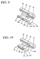
- the connector housings 10, 40 locked in the properly connected state are separated from each other as follows. First, the slider 20 in the displacement restricting position is moved forward to the forcible displacement position via the displacement permitting position against the biasing forces of the compression coil springs 26, the slanted surfaces 24A of the pushing portions 24 of the slider 20 come into contact with the slanted surface 18A of the lock arm 17 to thereby push it up as shown in FIG. 6(A) . In this way, the lock arm 17 in the locking position is forcibly displaced to the unlocking position to disengage the locking projection 17A from the locking surface 43 of the female connector housing 40, with the result that the connector housings 10, 40 are released from the locked state.
- the compression coil springs 26 are elastically compressed between the rear end surfaces of the spring chambers 25 of the slider 20 and the front surfaces of the pushing portions 44 of the female connector housing 40 as shown in FIG. 6(B) .
- the connector housings 10, 40 are released from the locked state and, simultaneously, the female connector housing 40 is pushed out of the receptacle 11 by the biasing forces of the compression coil springs 26.
Claims (5)
- Verbinder, der ein Paar miteinander verbindbare Verbindergehäuse (10, 40) umfasst, wobei ein Verbindergehäuse (10) umfasst:einen Arretier- bzw. Sperr- bzw. Verriegelungsarm (17), der im Wesentlichen zwischen einer Verriegelungsposition, in der das andere Verbindergehäuse (40) verriegelt ist, und einer Entriegelungsposition, in der das andere Verbindergehäuse (40) nicht verriegelt ist, elastisch verformbar ist, undeinen Schieber (20), der beweglich ist zwischen einer Verschiebungs-Beschränkungsposition (Fig. 5), in der eine Verschiebung des Verriegelungsarms (17) in der Verriegelungsposition in Richtung der Entriegelungsposition beschränkt ist, und einer Verschiebungs-Zulassungsposition (Fig. 1 - 4), in der die Verschiebung des Verriegelungsarms (17) in Richtung der Entriegelungsposition erlaubt ist, wobei die Verbindergehäuse (10, 40) derart aufgebaut sind, dass sie ineinander verriegelt werden, indem der Verriegelungsarm (17) in die Verriegelungsposition verschoben wird, um das andere Verbindergehäuse (40) zu verriegeln, und der Schieber (20) zu der Verschiebungs-Beschränkungsposition (Fig. 5) bewegt wird, während sie aus dem Verriegelungszustand gelöst werden, um sie voneinander zu trennen, indem der Schieber (20) in die Verschiebungs-Zulassungsposition (Fig. 1 - 4) bewegt wird, und der Verriegelungsarm (17) in die Entriegelungsposition verschoben wird, wobei der Verbinder ferner umfasst:ein Haltemittel (30), das seine Bewegung in Richtung der Verschiebungs-Beschränkungsposition (Fig. 5) beschränkt, undein Vorspannmittel (26) zum Vorspannen des Schiebers (20) von der Seite der gewaltsamen Verschiebungsposition (Fig. 6) in Richtung der Seite der Verschiebungs-Zulassungsposition (Fig. 1 - 4),wobei die Beschränkung des Schiebers (20) in Richtung der Verschiebungs-Beschränkungsposition (Fig. 5) durch das Haltemittel mittels geneigter Flächen (33, 45) gelöst wird, die an dem Haltemittel (30) und dem anderen Verbindergehäuse (40) ausgebildet sind, welche in Kontakt miteinander kommen, wenn das eine Verbindergehäuse (10) richtig mit dem anderen Verbindergehäuse (40) verbunden ist, dadurch gekennzeichnet, dassdas Haltemittel (30) ferner eine Bewegung des Schiebers (20) von der Verschiebungs-Zulassungsposition (Fig. 1 - 4) in Richtung einer gewaltsamen Verschiebungsposition (Fig. 6) erlaubt, und dadurch, dassder Schieber (20) ferner von der Verschiebungs-Zulassungsposition (Fig. 1 - 4) in die gewaltsame Verschiebungsposition (Fig. 6) beweglich ist, und dadurch, dassgewaltsame Verschiebungsmittel (18,24) in dem Schieber (20) und dem Verriegelungsarm (17) bereitgestellt sind, die den Verriegelungsarm (17) gewaltsam von der Verriegelungsposition zu der Entriegelungsposition verschieben, wenn der Schieber (20) von der Verschiebungs-Zulassungsposition (Fig. 1 - 4) in die gewaltsame Verschiebungsposition (Fig. 6) verschoben wird, und dadurch, dassdie gewaltsamen Verschiebungsmittel (18,24) einen auf dem Schieber (20) ausgebildeten Schub- bzw. Druckabschnitt (24) und einen auf dem Verriegelungsarm (17) ausgebildeten drückbaren Abschnitt (18) umfassen; und dadurch, dassder Druckabschnitt (24) und/oder der drückbare Abschnitt (18) mit einer geneigten Fläche (18A; 24A) ausgebildet sind, die sowohl in Bezug auf die Bewegungsrichtungen des Schiebers (209 als auch die Verschiebungsrichtungen der Verriegelungsarms (17) geneigt sind.
- Verbinder nach Anspruch 1, wobei die gewaltsame Verschiebungsposition (Fig. 6) sich in Bezug auf die Verschiebungs-Zulassungsposition (Fig. 5) auf der im Wesentlichen entgegengesetzten Seite von der Verschiebungsbeschränkungsposition befindet.
- Verbinder nach Anspruch 1, wobei das Vorspannmittel (26) eine Vorspannkraft speichert, um das andere Verbindergehäuse (40) zu trennen, indem es von dem anderen Verbindergehäuse (40, das verbunden ist, elastisch verformt wird.
- Verbinder nach einem oder mehreren der vorangehenden Ansprüche, wobei der Schieber (20) einen Kurzschlussanschluss (35) zum Kurzschließen von Anschlusshalterungen (13), die in dem einen Verbindergehäuse (10) bereitgestellt sind, umfasst.
- Verbinder nach Anspruch 4, wobei der Kurzschlussanschluss (35) die Anschlusshalterungen (13) kurzschließt, wenn der Schieber in der Verschiebungs-Zulassungsposition (Fig. 1 - 4) und/oder der gewaltsamen Verschiebungsposition (Fig. 6) ist, während der kurzgeschlossene Zustand der Anschlusshalterungen (13) gelöst wird, wenn der Schieber in der Verschiebungs-Beschränkungsposition (Fig. 5) ist.
Applications Claiming Priority (2)
| Application Number | Priority Date | Filing Date | Title |
|---|---|---|---|
| JP26923799 | 1999-09-22 | ||
| JP26923799A JP3504894B2 (ja) | 1999-09-22 | 1999-09-22 | コネクタ |
Publications (3)
| Publication Number | Publication Date |
|---|---|
| EP1087470A2 EP1087470A2 (de) | 2001-03-28 |
| EP1087470A3 EP1087470A3 (de) | 2001-06-27 |
| EP1087470B1 true EP1087470B1 (de) | 2008-11-19 |
Family
ID=17469578
Family Applications (1)
| Application Number | Title | Priority Date | Filing Date |
|---|---|---|---|
| EP00120583A Expired - Lifetime EP1087470B1 (de) | 1999-09-22 | 2000-09-20 | Ein Verbinder |
Country Status (4)
| Country | Link |
|---|---|
| US (1) | US6319041B1 (de) |
| EP (1) | EP1087470B1 (de) |
| JP (1) | JP3504894B2 (de) |
| DE (1) | DE60040824D1 (de) |
Families Citing this family (5)
| Publication number | Priority date | Publication date | Assignee | Title |
|---|---|---|---|---|
| JP3674521B2 (ja) | 2001-03-07 | 2005-07-20 | 住友電装株式会社 | コネクタ |
| EP1333541B1 (de) | 2002-01-30 | 2007-03-07 | Sumitomo Wiring Systems, Ltd. | Verbinder |
| FR2870647B1 (fr) | 2004-05-19 | 2006-08-25 | Cie Deutsch Societe Par Action | Connecteur auto-centre a verrouillage inertiel |
| JP2008159504A (ja) * | 2006-12-26 | 2008-07-10 | Sumitomo Wiring Syst Ltd | コネクタ |
| CN217740931U (zh) * | 2022-02-24 | 2022-11-04 | 长春捷翼汽车零部件有限公司 | 电连接装置及插头连接器 |
Citations (2)
| Publication number | Priority date | Publication date | Assignee | Title |
|---|---|---|---|---|
| EP1049213A1 (de) * | 1999-04-28 | 2000-11-02 | Yazaki Corporation | Verbindungsvorrichtung für Steckverbinder |
| EP1054481A1 (de) * | 1999-05-19 | 2000-11-22 | Sumitomo Wiring Systems, Ltd. | Ein Verbinder |
Family Cites Families (5)
| Publication number | Priority date | Publication date | Assignee | Title |
|---|---|---|---|---|
| US5672073A (en) * | 1994-06-14 | 1997-09-30 | Yazaki Corporation | Connector having engagement detecting device |
| US5571030A (en) * | 1995-01-09 | 1996-11-05 | General Motors Corporation | Protected connector assembly having double ended shorting clip |
| JPH09219255A (ja) * | 1996-02-07 | 1997-08-19 | Yazaki Corp | 二重ロックコネクタ |
| JP3086849B2 (ja) | 1996-08-06 | 2000-09-11 | 矢崎総業株式会社 | コネクタ嵌合構造 |
| JP3468451B2 (ja) * | 1997-09-09 | 2003-11-17 | 矢崎総業株式会社 | コネクタ嵌合構造 |
-
1999
- 1999-09-22 JP JP26923799A patent/JP3504894B2/ja not_active Expired - Lifetime
-
2000
- 2000-09-20 EP EP00120583A patent/EP1087470B1/de not_active Expired - Lifetime
- 2000-09-20 DE DE60040824T patent/DE60040824D1/de not_active Expired - Lifetime
- 2000-09-21 US US09/666,439 patent/US6319041B1/en not_active Expired - Lifetime
Patent Citations (2)
| Publication number | Priority date | Publication date | Assignee | Title |
|---|---|---|---|---|
| EP1049213A1 (de) * | 1999-04-28 | 2000-11-02 | Yazaki Corporation | Verbindungsvorrichtung für Steckverbinder |
| EP1054481A1 (de) * | 1999-05-19 | 2000-11-22 | Sumitomo Wiring Systems, Ltd. | Ein Verbinder |
Also Published As
| Publication number | Publication date |
|---|---|
| DE60040824D1 (de) | 2009-01-02 |
| EP1087470A2 (de) | 2001-03-28 |
| EP1087470A3 (de) | 2001-06-27 |
| JP3504894B2 (ja) | 2004-03-08 |
| JP2001093617A (ja) | 2001-04-06 |
| US6319041B1 (en) | 2001-11-20 |
Similar Documents
| Publication | Publication Date | Title |
|---|---|---|
| US6712635B1 (en) | Connector | |
| EP1089393B1 (de) | Verbinder | |
| US6824417B1 (en) | Connection detecting connector and a connection detecting connector assembly | |
| EP0841724B1 (de) | Ein Verbinder | |
| US7223113B2 (en) | Connector and a connector assembly | |
| EP0827236B1 (de) | Elektrischer Steckverbinder | |
| US6942510B2 (en) | Connector and a connector system | |
| EP1638175A2 (de) | Ein Verbinder und eine Verbinderanordnung | |
| EP1233480B1 (de) | Verbinder und Zusammenbauverfahren dafür | |
| US7059902B2 (en) | Connector, a connector assembly and a method of assembling a connector assembly | |
| US6786754B2 (en) | Connector and a connector assembly | |
| EP1085617B1 (de) | Verbinder | |
| EP1087470B1 (de) | Ein Verbinder | |
| US20220271473A1 (en) | Connector | |
| US6638098B2 (en) | Connection detecting connector | |
| US6595795B2 (en) | Connector and a method of assembling a connector | |
| US6572394B1 (en) | Connector and use thereof | |
| US6551146B2 (en) | Connector and a method for assembling a connector | |
| US20030143885A1 (en) | Connector | |
| US6679720B2 (en) | Connector and a method for assembling a connector | |
| US6953364B2 (en) | Connector, a shorting terminal and a method of assembling it | |
| US6530800B2 (en) | Connector and method for assembling a connector | |
| US20030040211A1 (en) | Connector | |
| JP3468356B2 (ja) | コネクタ |
Legal Events
| Date | Code | Title | Description |
|---|---|---|---|
| PUAI | Public reference made under article 153(3) epc to a published international application that has entered the european phase |
Free format text: ORIGINAL CODE: 0009012 |
|
| 17P | Request for examination filed |
Effective date: 20001012 |
|
| AK | Designated contracting states |
Kind code of ref document: A2 Designated state(s): DE FR GB IT |
|
| AX | Request for extension of the european patent |
Free format text: AL;LT;LV;MK;RO;SI |
|
| PUAL | Search report despatched |
Free format text: ORIGINAL CODE: 0009013 |
|
| AK | Designated contracting states |
Kind code of ref document: A3 Designated state(s): AT BE CH CY DE DK ES FI FR GB GR IE IT LI LU MC NL PT SE |
|
| AX | Request for extension of the european patent |
Free format text: AL;LT;LV;MK;RO;SI |
|
| AKX | Designation fees paid |
Free format text: DE FR GB IT |
|
| 17Q | First examination report despatched |
Effective date: 20041012 |
|
| GRAP | Despatch of communication of intention to grant a patent |
Free format text: ORIGINAL CODE: EPIDOSNIGR1 |
|
| GRAS | Grant fee paid |
Free format text: ORIGINAL CODE: EPIDOSNIGR3 |
|
| GRAA | (expected) grant |
Free format text: ORIGINAL CODE: 0009210 |
|
| AK | Designated contracting states |
Kind code of ref document: B1 Designated state(s): DE FR GB IT |
|
| REG | Reference to a national code |
Ref country code: GB Ref legal event code: FG4D |
|
| REF | Corresponds to: |
Ref document number: 60040824 Country of ref document: DE Date of ref document: 20090102 Kind code of ref document: P |
|
| PLBE | No opposition filed within time limit |
Free format text: ORIGINAL CODE: 0009261 |
|
| STAA | Information on the status of an ep patent application or granted ep patent |
Free format text: STATUS: NO OPPOSITION FILED WITHIN TIME LIMIT |
|
| 26N | No opposition filed |
Effective date: 20090820 |
|
| GBPC | Gb: european patent ceased through non-payment of renewal fee |
Effective date: 20090920 |
|
| PG25 | Lapsed in a contracting state [announced via postgrant information from national office to epo] |
Ref country code: GB Free format text: LAPSE BECAUSE OF NON-PAYMENT OF DUE FEES Effective date: 20090920 |
|
| PG25 | Lapsed in a contracting state [announced via postgrant information from national office to epo] |
Ref country code: IT Free format text: LAPSE BECAUSE OF FAILURE TO SUBMIT A TRANSLATION OF THE DESCRIPTION OR TO PAY THE FEE WITHIN THE PRESCRIBED TIME-LIMIT Effective date: 20081119 |
|
| PGFP | Annual fee paid to national office [announced via postgrant information from national office to epo] |
Ref country code: DE Payment date: 20130918 Year of fee payment: 14 |
|
| PGFP | Annual fee paid to national office [announced via postgrant information from national office to epo] |
Ref country code: FR Payment date: 20130910 Year of fee payment: 14 |
|
| REG | Reference to a national code |
Ref country code: DE Ref legal event code: R119 Ref document number: 60040824 Country of ref document: DE |
|
| REG | Reference to a national code |
Ref country code: DE Ref legal event code: R119 Ref document number: 60040824 Country of ref document: DE Effective date: 20150401 |
|
| REG | Reference to a national code |
Ref country code: FR Ref legal event code: ST Effective date: 20150529 |
|
| PG25 | Lapsed in a contracting state [announced via postgrant information from national office to epo] |
Ref country code: DE Free format text: LAPSE BECAUSE OF NON-PAYMENT OF DUE FEES Effective date: 20150401 |
|
| PG25 | Lapsed in a contracting state [announced via postgrant information from national office to epo] |
Ref country code: FR Free format text: LAPSE BECAUSE OF NON-PAYMENT OF DUE FEES Effective date: 20140930 |