EP1087330A2 - Two-dimensional dot code and reader thereof - Google Patents
Two-dimensional dot code and reader thereof Download PDFInfo
- Publication number
- EP1087330A2 EP1087330A2 EP00120536A EP00120536A EP1087330A2 EP 1087330 A2 EP1087330 A2 EP 1087330A2 EP 00120536 A EP00120536 A EP 00120536A EP 00120536 A EP00120536 A EP 00120536A EP 1087330 A2 EP1087330 A2 EP 1087330A2
- Authority
- EP
- European Patent Office
- Prior art keywords
- dot
- code
- dots
- dot code
- image processing
- Prior art date
- Legal status (The legal status is an assumption and is not a legal conclusion. Google has not performed a legal analysis and makes no representation as to the accuracy of the status listed.)
- Withdrawn
Links
Images










Classifications
-
- G—PHYSICS
- G06—COMPUTING OR CALCULATING; COUNTING
- G06K—GRAPHICAL DATA READING; PRESENTATION OF DATA; RECORD CARRIERS; HANDLING RECORD CARRIERS
- G06K7/00—Methods or arrangements for sensing record carriers, e.g. for reading patterns
- G06K7/10—Methods or arrangements for sensing record carriers, e.g. for reading patterns by electromagnetic radiation, e.g. optical sensing; by corpuscular radiation
- G06K7/14—Methods or arrangements for sensing record carriers, e.g. for reading patterns by electromagnetic radiation, e.g. optical sensing; by corpuscular radiation using light without selection of wavelength, e.g. sensing reflected white light
- G06K7/1404—Methods for optical code recognition
- G06K7/1408—Methods for optical code recognition the method being specifically adapted for the type of code
- G06K7/1417—2D bar codes
-
- G—PHYSICS
- G06—COMPUTING OR CALCULATING; COUNTING
- G06K—GRAPHICAL DATA READING; PRESENTATION OF DATA; RECORD CARRIERS; HANDLING RECORD CARRIERS
- G06K19/00—Record carriers for use with machines and with at least a part designed to carry digital markings
- G06K19/06—Record carriers for use with machines and with at least a part designed to carry digital markings characterised by the kind of the digital marking, e.g. shape, nature, code
- G06K19/06009—Record carriers for use with machines and with at least a part designed to carry digital markings characterised by the kind of the digital marking, e.g. shape, nature, code with optically detectable marking
- G06K19/06037—Record carriers for use with machines and with at least a part designed to carry digital markings characterised by the kind of the digital marking, e.g. shape, nature, code with optically detectable marking multi-dimensional coding
-
- G—PHYSICS
- G06—COMPUTING OR CALCULATING; COUNTING
- G06K—GRAPHICAL DATA READING; PRESENTATION OF DATA; RECORD CARRIERS; HANDLING RECORD CARRIERS
- G06K7/00—Methods or arrangements for sensing record carriers, e.g. for reading patterns
- G06K7/01—Details
- G06K7/016—Synchronisation of sensing process
- G06K7/0163—Synchronisation of sensing process by means of additional timing marks on the record-carrier
-
- G—PHYSICS
- G06—COMPUTING OR CALCULATING; COUNTING
- G06K—GRAPHICAL DATA READING; PRESENTATION OF DATA; RECORD CARRIERS; HANDLING RECORD CARRIERS
- G06K7/00—Methods or arrangements for sensing record carriers, e.g. for reading patterns
- G06K7/10—Methods or arrangements for sensing record carriers, e.g. for reading patterns by electromagnetic radiation, e.g. optical sensing; by corpuscular radiation
- G06K7/10544—Methods or arrangements for sensing record carriers, e.g. for reading patterns by electromagnetic radiation, e.g. optical sensing; by corpuscular radiation by scanning of the records by radiation in the optical part of the electromagnetic spectrum
- G06K7/10712—Fixed beam scanning
- G06K7/10722—Photodetector array or CCD scanning
-
- G—PHYSICS
- G06—COMPUTING OR CALCULATING; COUNTING
- G06K—GRAPHICAL DATA READING; PRESENTATION OF DATA; RECORD CARRIERS; HANDLING RECORD CARRIERS
- G06K7/00—Methods or arrangements for sensing record carriers, e.g. for reading patterns
- G06K7/10—Methods or arrangements for sensing record carriers, e.g. for reading patterns by electromagnetic radiation, e.g. optical sensing; by corpuscular radiation
- G06K7/10544—Methods or arrangements for sensing record carriers, e.g. for reading patterns by electromagnetic radiation, e.g. optical sensing; by corpuscular radiation by scanning of the records by radiation in the optical part of the electromagnetic spectrum
- G06K7/10712—Fixed beam scanning
- G06K7/10762—Relative movement
Definitions
- This invention relates to a two-dimensional dot code and a reader thereof and in particular to a two-dimensional dot code and a reader thereof for making it possible to read a dot code more accurately.
- the two-dimensional dot code comprises a plurality of cells as basic units in two dimensions to represent a predetermined code.
- Such a two-dimensional dot code in a related art often is imaged by a video camera, etc., for example, and is read from the provided image.
- a video camera etc.
- cells as basic units need to be made large to some extent because of the nature of the two-dimensional dot code. Consequently, the two-dimensional dot code itself requires a comparatively large area; this is a problem.
- the dot code is represented based on the presence or absence of dots as the minimum units that can be represented by a printer, for example, as shown in FIG. 1. Therefore, it is made possible to represent more codes in a narrow range.
- the dot positions of such a two-dimensional dot code change because of variations in printer heads. Consequently, a dot may be printed at a print position P2 at a distance of a predetermined offset amount from an original print position P1, for example, as shown in FIG. 1.
- a dot may be printed at a print position P2 at a distance of a predetermined offset amount from an original print position P1, for example, as shown in FIG. 1.
- the offset is large, it is feared that the two-dimensional dot code may be read in error as if a dot were not printed although the dot is printed actually.
- Such a read error can be prevented to some extent by enhancing the precision of a printer for printing two-dimensional dot code or a scanner for reading the code; however, to do this, it becomes necessary to manufacture a high-precision printer or scanner, resulting in an increase in costs; this is a problem.
- timing marks for indicating the positions of dots for representing the code is provided at at least one end on a line in a direction perpendicular to the read direction of the dots for representing the code.
- a reader comprises first detection means for detecting the positions of timing marks placed at both ends on the lines in a direction perpendicular to the read direction of the dots for representing a code; and second detection means for detecting the dots representing the code placed between the timing marks based on the timing marks at both ends detected by the first detection means.
- the timing marks for indicating the positions of dots for representing the code are placed at at least one end on a line in a direction perpendicular to the read direction of the dots for representing the code.
- the dots representing the code placed between the timing marks are detected based on the timing marks placed at both ends on the lines in a direction perpendicular to the read direction of the dots for representing the code.
- FIG. 2 shows a configuration example of a printer incorporating the invention.
- a CPU 13 of a printer 11 controls a print head transporter 15, a print head 16, and a paper transporter 17 in response to a command from an input section 12 made up of buttons, switches, etc.
- the print head transporter 15 transports the print head 16 in a subscanning direction in response to a command from the CPU 13.
- the print head 16 prints a two-dimensional dot code 2 on a card 1 in response to a print head control signal from the CPU 13.
- the paper transporter 17 transports the card 1 to a predetermined position in response to a command from the CPU 13.
- Memory 18 stores under the control of the CPU 13, data supplied through a communication section 14 via a network such as a LAN.
- the print head 13 has a plurality of print nozzles 101 for jetting ink to the card 1, thereby printing the two-dimensional dot code 2 consisting of dots.
- the operation is as follows:
- the CPU 13 reads print data through the communication section 14 and stores the print data in the memory 18.
- the CPU 13 controls the paper transporter 17 for transporting the card 1 to a predetermined position.
- the CPU 13 converts the read print data into a print head control signal and supplies the print head control signal to the print head 16 and controls the print head transporter 15 for moving the print head 16 in the subscanning direction relatively to the card 1.
- the print nozzles 101 of the print head 16 jet ink 102 for printing the two-dimensional dot code 2 consisting of dots on the card 1.
- FIG. 3 shows a configuration example of the two-dimensional dot code 2 thus printed on the card 1.
- a start position mark 31 is printed as one row of dots at the beginning.
- the start position mark 31 is followed by a blank row, followed by left and right timing marks 32L and 32R and a data mark 33 which are printed.
- the dots making up the left and right timing marks 32L and 32R are printed on all rows.
- the dots making up the data mark 33 are printed corresponding to the code.
- Printing is executed in order starting at the start position mark 31, from top to bottom (in the subscanning direction in FIG. 3. In other words, the print head 16 is transported front top to bottom.
- timing marks 32L and 32R are thus printed, whether or not dots exist is determined on the line connecting the timing marks 32L and 32R at the left and right ends, whereby it is made possible to accurately determine whether or not the dots making up the data mark 33 exist.
- the timing marks 32L and 32R are printed on every row as shown in FIG. 3, the dots making up the timing mark 32L, 32R may overlap each other because of a position shift.
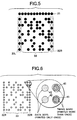
- the timing marks 32L and 32R can be printed at predetermined intervals (in the figure in FIG. 4, every other row).
- the timing marks 32L and 32R can be printed alternately (if a dot of the timing mark 32L is printed, a dot of the timing mark 32R is not printed on the row; if a dot of the timing mark 32R is printed, a dot of the timing mark 32L is not printed on the row).
- the dots of the timing mark 32L, 32R can be prevented from overlapping from top to bottom. Consequently, the positions of the timing marks 32L and 32R can be detected accurately and by extension whether or not the dots of the data mark 33 based on the timing marks 32L and 32R can be determined accurately.
- the timing marks 32L and 32R need to be printed reliably as much as possible so that they can be read. Then, for example, as shown in FIG. 6, the timing marks 32L and 32R may be printed more than once although the data mark 33 is read only once. In doing so, dots 41 making up the timing mark 32L, 32R are represented in dark color as compared with dots 42 making up the data mark 33 as shown in FIG. 6, and at the read time, the fear that the dots printed in fair ink color cannot be read is lessened.
- FIG. 7 shows a configuration example of a reader 61 for reading the card 1 on which the two-dimensional dot code 2 is thus printed.
- the reader 61 has a control circuit 62 implemented as a microcomputer, etc., for example, for controlling a light source 63 for generating light to illuminate the card 1 on which the two-dimensional dot code 2 is printed.
- a read element 64 implemented as a CCD row sensor, etc., is controlled by the control circuit 62 for reading the two-dimensional dot code 2 on the card 1 and outputting the read image signal to an A/D conversion section 65.
- the A/D conversion section 65 converts the analog input image signal into a digital image signal and outputs the digital image signal to a dot code image processing circuit 66.
- a synchronizing signal synchronized with reading the two-dimensional dot code 2 is also supplied to the dot code image processing circuit 66 from the control circuit 62.
- the dot code image processing circuit 66 reads the image data input from the A/D conversion section 65 in synchronization with the synchronizing signal and outputs the read result to an external system.
- the read element 64 electronically scans in the main scanning direction (horizontal direction in FIG. 3) and the subscanning direction (from top to bottom in FIG. 3).
- the reader 61 has a higher resolution than the printer 11 has. For example, assuming that one dot printed on the printer 11 corresponds to three X three pixels of the reader 61, an image read by the reader 61 becomes as shown in FIG. 8. That is, the center pixel of the three X three pixels becomes the darkest, the four pixels above and below and at the left and right of the center pixel become the second darkest, and the four pixels slantingly adjacent to the center pixel become the lightest.
- step S1 the dot code image processing circuit 66 executes processing of detecting a start position mark 31.
- step S2 the dot code image processing circuit 66 determines whether or not the start position mark 31 is detected. If the start position mark 31 is not yet detected, the dot code image processing circuit 66 returns to step S1 and again executes processing of detecting a start position mark 31.
- the start position mark 31 is printed over a predetermined width on one row in the direction perpendicular to the transport direction of the card 1 (subtransporting direction) as shown in FIG. 3, thus whether or not the start position mark 31 is detected can be checked from the fact.
- step S3 the dot code image processing circuit 66 proceeds to step S3 and computes the center coordinates of the start position mark 31.
- dot detection processing shown in FIG. 13 may be executed although a detailed description is given later.
- step S4 the dot code image processing circuit 66 proceeds to step S4 and executes detection processing of timing marks 32L and 32R.
- step S5 the dot code image processing circuit 66 determines whether or not the tinting marks 32L and 32R are detected. If the timing marks 32L and 32R are not detected, the dot code image processing circuit 66 returns to step S4 and again executes the detection processing.
- Each timing mark is printed at the left and right end parts of the data mark 33 in the direction perpendicular to the start position mark 31 (parallel direction with the subscanning direction) as shown in FIG. 3, thus whether or not the timing marks are detected can be checked from the fact.
- dot detection processing shown in FIG. 13 may be executed.
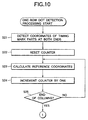
- step S6 the dot code image processing circuit 66 proceeds to step S6 and executes one-row dot detection processing described later in detail with reference to flowcharts of FIGS. 10 and 11.
- step S7 in a slanting direction determines whether or not processing of the data mark 33 corresponding to the timing marks 32L and 32R on all rows terminates. If the processing does not yet terminate, the dot code image processing circuit 66 returns to step S4 and repeats step S4 and the later steps. If it is determined at step S7 that processing of the data mark 33 corresponding to the timing marks 32L and 32R on all rows terminates, the dot read processing is terminated.
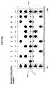
- the dot code image processing circuit 66 detects the coordinates of the timing marks 32L and 32R at both ends. For example, now assuming that processing of the third row from the top of FIG. 12 is performed, the x and y coordinates of the timing mark parts 32L1 and 32R1 are detected. That is, the coordinates of points P1 and P12 in FIG. 12 are detected.
- the dot code image processing circuit 66 resets a counter for counting the number of columns.
- the dot code image processing circuit 66 computes a line L1 provided by connecting the centers of the timing mark parts 32L1 and 32R1 and calculates reference coordinates x2 and y2 defining the leftmost dot position of the data mark 33 defined by the start position mark 31 on the line L1 (ideally, the value of y2 becomes equal to the value of y1 of the y coordinate of the point P1). That is, the coordinates of point P2 (x2, y2) in FIG. 12 are calculated.
- the dot code image processing circuit 66 increments the counter reset at step S22 by one and determines whether or not the counter value becomes larger than the number of columns of the data mark 33, namely, whether or not processing for all columns of the data mark 33 terminates. If the processing does not yet terminate, the dot code image processing circuit 66 returns to step S23 and executes processing of calculating the reference coordinates of the next column.
- FIG. 13 is a flowchart to show the dot detection processing in detail. The processing shown in the flowchart of FIG. 13 is performed for the following purpose: If a dot D21 is printed shifting from original print position (reference coordinates) P21, for example, as shown in FIG. 14, it is feared that a dot may be determined to be not printed at the print position P21. Then, in the invention, as shown in FIG. 15, from the original print position P21, the center coordinates thereof are moved in a search range W and whether or not a dot exists in the search range W is determined.
- the dot code image processing circuit 66 determines whether or not the density of the pixel in the coordinates (x, y) on which attention is focused is greater than a predetermined threshold value. For example, the dot code image processing circuit 66 determines whether or not the density of the pixel at the point P2 shown in FIG. 12 is greater than a predetermined threshold value. If the density of the pixel is greater than the threshold value, the dot code image processing circuit 66 proceeds to step S62 and determines that a dot exists at the reference position.
- step S61 If it is determined at step S61 that the density of the pixel in the coordinates (x, y) on which attention is focused is equal to or less than the predetermined threshold value, the dot code image processing circuit 66 proceeds to step S63 and resets an internal counter.
- the counter indicates the number of times a search has been executed in the search range W previously described with reference to FIG. 15.
- the dot code image processing circuit 66 checks the densities of the eight pixels surrounding the pixel in the coordinates (x, y) on which attention is focused. That is, the pixel in the coordinates (x, y) on which attention is focused is the center pixel of three X three pixels and therefore the densities of the four pixels above and below and at the left and right of the center pixel and the four pixels slantingly adjacent to the center pixel are checked.
- the dot code image processing circuit 66 moves the center pixel of the dot to the pixel in coordinates (x', y') at the highest density. If more than one pixel at the highest density exists among the eight surrounding pixels, the priority levels of the move order are preset from the upper-left corner to the lower-right corner as shown in FIG. 16 and the center pixel of the dot is moved to the highest-priority pixel.
- the dot code image processing circuit 66 determines whether or not the density of the pixel in the coordinates (x', y') is greater than a threshold value, which is the same value as the threshold value at step S61.
- step S66 If it is determined at step S66 that the density of the pixel in the coordinates (x', y') on which attention is focused is greater than the threshold value, the dot code image processing circuit 66 goes to step S62 and determines that a dot is printed at the position.
- step S66 If it is determined at step S66 that the density of the pixel in the coordinates (x', y') on which attention is focused is equal to or less than the threshold value, the dot code image processing circuit 66 proceeds to step S67 and increments a counter indicating the number of times a move has been made to the eight surrounding pixels by one, then proceeds to step S68 and sets the coordinates (x', y') on which attention is focused to the coordinates (x, y) of the center of the three X three pixels, whereby the center pixel of the three X three pixels is moved.
- step S69 the dot code image processing circuit 66 determines whether or not the counter value is smaller than the predetermined number of times (for example, two). If the counter value is smaller than the predetermined number of times, the dot code image processing circuit 66 returns to step S64 and repeats step S64 and the later steps.
- the predetermined number of times for example, two.
- step S69 It is determined at step S69 that the counter value is not smaller than the predetermined number of times (is equal to the predetermined number of times), the dot code image processing circuit 66 proceeds to step S70 and determines that a dot does not exist at the position.
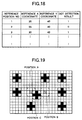
- the dot code image processing circuit 66 collates the coordinates of the dot detected at step S27 with a detected dot list. That is, the dot code image processing circuit 66 registers the coordinates of the dot calculated at step S29 (detected x coordinate and detected y coordinate) in the detected dot list in internal memory together with the distance d of the coordinates from the reference coordinates and the reference position number corresponding to the detected dot at step S36 (described later), as shown in FIG. 17.
- List numbers are assigned to the entries as shown in FIG. 17.
- the reference position numbers are numbers given corresponding to the reference positions from the leftmost coordinate x2 of the data mark 33 to the rightmost coordinate x11, for example, as shown in FIG. 12; numbers 1 to 10 are the reference position numbers in the example in FIG. 12.
- the dot code image processing circuit 66 determines whether or not the coordinates corresponding to the detected coordinates are registered in the detected dot list. If the corresponding coordinates are not registered in the detected dot list, the dot code image processing circuit 66 goes to step 36 and registers the center coordinates of the detected dot (x', y'), the reference position number to which the reference coordinates at the time correspond, and the distance d calculated at step S29 in the detected dot list, as shown in FIG. 17. Further, at step S18, the dot code image processing circuit 66 sets the value of the dot detection result corresponding to the reference position number being processed in a dot detection result list in the internal memory to 1, as shown in FIG. 18.
- the dot code image processing circuit 66 determines at step S31 that the coordinates corresponding to the detected dot coordinates are already registered in the detected dot list, the dot code image processing circuit 66 goes to step 32 and loads (read) distance d' corresponding to the coordinates already registered in the detected dot list. Then, at step S33, the dot code image processing circuit 66 compares the distanced calculated at step S29 with the distance d' read from the detected dot list and if the distance d is less than the distance d', the dot code image processing circuit 66 proceeds to step S34 and corrects the value of the dot detection result corresponding to the reference position number corresponding to the detected dot coordinates in the detected dot list to 0. As shown in FIG.
- the dot detection result list stores each reference position number, reference coordinates (reference x coordinate and reference y coordinate) corresponding thereto, and the dot detection result.
- the dot detection result value 1 represents that the dot corresponding to the reference position number is detected, and the value 0 represents that the dot corresponding to the reference position number is not detected.
- the dot code image processing circuit 66 deletes the data of the detected coordinates already registered from the detected dot list (FIG. 17) as erroneous determination.
- the dot code image processing circuit 66 registers the coordinates of the dot detected at step S27, the current reference position number being processed, and the distance d calculated at step S29 in the detected dot list (FIG. 17). Further, at step S37, the dot code image processing circuit 66 sets the value of the dot detection result corresponding to the current reference position number being processed in the dot detection result list (FIG. 18) to 1.
- step S33 determines at step S33 that the distance d is not smaller than the distance d', it proceeds to step S39 and sets the value of the dot detection result corresponding to the current reference position number being processed to 0.
- the dot to be printed at the original position (reference coordinates) A is printed shifting to position C as shown in FIG. 19, the following is prevented: After it is determined that the dot at the position C is printed at the position A, it is also determined that the dot at the position C is printed at another position (reference coordinates) B, namely, it is doubly determined that the dot at the position C is printed at both the positions A and B.
- the dot code image processing circuit 66 proceeds to step S40 and increments the counter by one.
- the dot code image processing circuit 66 determines whether or not the value of the counter incremented by one at step S40 becomes greater than the maximum value of the number of dots of the data mark 33 contained in one row (the number of columns of the data mark 33). If the counter value does not become greater than the maximum value, the dot code image processing circuit 66 returns to step S27 and repeats step S27 and the later steps. If it is determined at step S41 that the counter value becomes greater than the maximum value of the number of dots in one row, the processing is terminated.
- the relative transport speed between the card 1 and the reader 64 does not necessarily become the reference transfer speed in some cases. If the relative transport speed becomes lower than the reference transfer speed, for example, if the relative speed becomes a half the reference speed, one dot to be originally read as three X three pixels is read as 16 pixels as shown in FIG. 20. That is, at this time, the number of pixels in the main scanning direction (lateral direction in FIG. 20) remains to be three, but the number of pixels in the subscanning direction (longitudinal direction in FIG. 20) is increased to six at the center and four at the left and right.
- the search range W can be made longer in the subscanning direction (relative transport direction of the card 1), as shown in FIG. 20, so that if the relative transport speed of the card 1 in the subscanning direction changes and the image is expanded in the subscanning direction, it is made possible to detect dots more reliably.
- the timing mark detection processing at step S4 in FIG. 9 is executed as shown in a flowchart of FIG. 21. That is, at step S91, the dot code image processing circuit 66 detects the left timing mark 32L and at step S92, calculates the aspect ratio of the left timing mark 32L.
- the dot code image processing circuit 66 detects the right timing mark 32R and at step S94, calculates the aspect ratio of the right timing mark 32R.
- the dot code image processing circuit 66 calculates the average value of the aspect ratios calculated at steps S92 and S94.
- the dot code image processing circuit 66 adopts the value of multiplying the length of the original search range W1 in the longitudinal direction thereof (Y direction) by the average aspect ratio calculated at step S95 as the length of the corrected search range W2 in the longitudinal direction thereof, as shown in FIG. 20.
- the search range is changed in response to the expansion proportion. Consequently, it is made possible to determine whether or not a dot exists more accurately.
- FIG. 22 shows another example of a two-dimensional dot code.
- the start position mark 31 shown in FIG. 3 is printed on a plurality of rows (in the example in FIG. 22, five rows) to provide a printer head offset sense mark 51.
- the dot code image processing circuit 66 detects a start position mark at step S1 previously described with reference to FIG. 9, it further executes offset detection processing shown in FIG. 23.
- the dot code image processing circuit 66 resets an internal counter at step S101 and clears an internal buffer at step S102. At step S103, the dot code image processing circuit 66 detects the coordinates of the timing marks 32L and 32R at both ends. At step S104, the dot code image processing circuit 66 calculates the reference coordinates of each dot provided by dividing the line connecting the centers of the left and right timing marks 32L and 32R by the number of columns of the data mark 33.
- the dot code image processing circuit 66 executes the dot detection processing previously described with reference to the flowchart of FIG. 13.
- i denotes the row number and j denotes the column number.
- the dot code image processing circuit 66 stores the offset amount calculated at step S106 in the buffer.
- the dot code image processing circuit 66 determines whether or not processing for the one-row dots in each column is terminated. If any unprocessed dot remains in the row, the dot code image processing circuit 66 returns to step S105 and repeats step S105 and the later steps.
- step S108 determines at step S108 that the offset amount detection processing for the one-row dots terminates, it proceeds to step S110 and increments the counter for indicating the number of processed rows by one.
- step S110 the dot code image processing circuit 66 determines whether or not the counter value becomes greater than the stipulated number of rows set as the printer head offset sense mark 51. If the dot code image processing circuit 66 determines that the counter value does not become greater than the stipulated number of rows, it returns to step S103 and repeats step S103 and the later steps.
- the dot code image processing circuit 66 determines that the counter value becomes greater than the stipulated number of rows, it proceeds to step S111 and resets the counter value.
- the dot code image processing circuit 66 calculates the average value of the all-row offset amounts in one column. In the example in FIG. 22, the average value of five-row offset amounts in one column is calculated.
- the average value x a thus found is used as the coordinate x-2 representing the dot 31-2 in the column. This value is used as the coordinate x2 shown in FIG. 12.
- the dot code image processing circuit 66 stores the average value calculated at step S112 in the buffer as the offset amount of the nozzle of the corresponding column.
- the dot code image processing circuit 66 increments the counter for indicating the number of processed columns by one.
- the dot code image processing circuit 66 determines whether or not the counter value becomes greater than the predetermined number of columns (the number of columns of the data mark 33 in FIG. 22). If the dot code image processing circuit 66 determines that the counter value is not greater than the predetermined number of columns, it returns to step S112 and repeats step S112 and the later steps. If it is determined at step S115 that the counter value becomes greater than the predetermined number of columns, the offset detection processing is terminated.
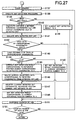
- Step S131 to S152 shown in FIGS. 26 and 27 basically are similar to steps S21 to S41 in FIGS. 10 and 11; however, step S134 is added between steps S133 and S135 in FIG. 26 corresponding to steps S23 and S24 in FIG. 10.
- the dot code image processing circuit 66 adds the offset amount provided in the processing previously described with reference to FIG. 23 to the reference coordinates calculated at step S133.
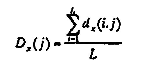
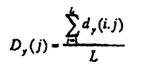
- the reference coordinates (x, y) in the column j is corrected as follows: (x + D x (j), y + D y (j)) where D x (j) and D y (j) denote the average value of the offset value in the x direction in the column j and the offset value in the y direction in the column j as in the following expressions: Average value of offset in x direction in column j Average value of offset in y direction in column j
- the dot code image processing circuit 66 thus determines the code from the presence or absence of each of the dots making up the data mark 33 and outputs the determination result.
- An error correction code can be contained in the code.
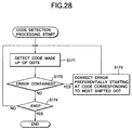
- the dot code image processing circuit 66 executes code detection processing as shown in FIG. 28.
- the dot code image processing circuit 66 detects a code made up of dots.
- the dot code image processing circuit 66 uses the error detection code contained in the code to determine whether or not the detected code contains an error. If an error is contained, the dot code image processing circuit 66 proceeds to step S173 and executes processing of correcting the error preferentially starting at the code corresponding to the dot most shifted from the reference position. Then, the dot code image processing circuit 66 returns to step S171 and repeats step S171 and the later steps.
- step S172 determines at step S172 that an error is not contained, it proceeds to step S174 and determines whether or not detection processing of all codes is terminated. If a code whose detection is not yet complete exists, the dot code image processing circuit 66 returns to step S171 and repeats step S171 and the later steps. If it is determined at step S174 that detection processing of all codes is terminated, the code detection processing is terminated.
- timing marks 132L and 132R for indicating positions of dots 133 for representing the code are provided at both ends (or one end) on lines in a direction perpendicular to a read direction of the dots 133 for representing the code.
- the shape of the timing marks 132L and 132R is the same as that of the dots 133 for representing the code.
- one dot is provided by one dot of the printer, and similarly, one timing mark is provided by one dot of the printer.
- Fig. 29A when an image is expanded due to the transport irregularity of reading, the timing marks at both ends are also expanded. Accordingly, it is possible to detect the transport irregularity by using the timing mark. Thus, it is possible to enhance the accuracy of the code recognition.
- the code is represented by one dot of the printer, and similarly, the timing mark is represented by one dot.
- the code is represented by one dot of the printer, and similarly, the timing mark is represented by one dot.
- the timing marks for indicating the positions of dots for representing the code are placed at at least one end on the line in a direction perpendicular to the read direction of the dots for representing the code.
- the positions of timing marks are detected and the dots representing the code placed between the timing marks are detected based on the timing marks, so that it is made possible to detect the presence or absence of each dot accurately.
Landscapes
- Physics & Mathematics (AREA)
- Engineering & Computer Science (AREA)
- Electromagnetism (AREA)
- Theoretical Computer Science (AREA)
- General Physics & Mathematics (AREA)
- Artificial Intelligence (AREA)
- Computer Vision & Pattern Recognition (AREA)
- Health & Medical Sciences (AREA)
- General Health & Medical Sciences (AREA)
- Toxicology (AREA)
- Printers Characterized By Their Purpose (AREA)
- Facsimile Scanning Arrangements (AREA)
- Character Input (AREA)
Abstract
Description
Claims (10)
- A two-dimensional dot code comprising:dots placed in two dimensions for representing a predetermined code, andtiming marks for indicating positions of the dots for representing the code at at least one end on a line in a direction perpendicular to a read direction of the dots for representing the code.
- The two-dimensional dot code as claimed in claim 1, wherein a shape of the timing marks is the same as that of the dots.
- The two-dimensional dot code as claimed in claim 1, wherein, in a case that each of the dots is provided by one dot of a printer, each of the timing marks is provided by one dot of a printer.
- The two-dimensional dot code as claimed in claim 1, wherein timing marks for indicating positions of the dots for representing the code is provided at both ends on lines in a direction perpendicular to a read direction of the dots for representing the code.
- The two-dimensional dot code as claimed in claim 1, wherein the timing mark is recorded more than once at the same position and is formed.
- The two-dimensional dot code as claimed in claim 1, wherein the dots contain dots for an error detection code.
- A reader for reading a two-dimensional dot code comprising dots placed in two dimensions for representing a predetermined code, said reader comprising:first detection means for detecting positions of timing marks placed at both ends on lines in a direction perpendicular to a read direction of the dots for representing the code; andsecond detection means for detecting the dots representing the code placed between the timing marks based on the timing marks at both ends detected by said first detection means.
- The reader as claimed in claim 7, wherein if the dot does not exist at the position with the timing mark as reference, said second detection means searches for the dot in the surroundings of the position.
- The reader as claimed in claim 7, wherein the dots contain dots for an error detection code, further including error correction means for making an error correction using the error detection code and upon detection of an error, for correcting preferentially an error caused by the dot most shifted from the position with the timing mark as reference.
- The reader as claimed in claim 7, wherein said second detection means detects a position shift of the dot placed before the dot representing the code and detects the dot representing the code based on the detected position shift.
Applications Claiming Priority (2)
| Application Number | Priority Date | Filing Date | Title |
|---|---|---|---|
| JP26684399 | 1999-09-21 | ||
| JP26684399 | 1999-09-21 |
Publications (2)
| Publication Number | Publication Date |
|---|---|
| EP1087330A2 true EP1087330A2 (en) | 2001-03-28 |
| EP1087330A3 EP1087330A3 (en) | 2002-04-10 |
Family
ID=17436444
Family Applications (1)
| Application Number | Title | Priority Date | Filing Date |
|---|---|---|---|
| EP00120536A Withdrawn EP1087330A3 (en) | 1999-09-21 | 2000-09-20 | Two-dimensional dot code and reader thereof |
Country Status (2)
| Country | Link |
|---|---|
| US (1) | US6533182B1 (en) |
| EP (1) | EP1087330A3 (en) |
Cited By (4)
| Publication number | Priority date | Publication date | Assignee | Title |
|---|---|---|---|---|
| EP1862939A1 (en) * | 2006-05-29 | 2007-12-05 | Shenzhen Syscan Technology Co., Ltd. | The two-directional bar code symbol and its encoding & decoding method |
| WO2008107001A1 (en) * | 2007-03-02 | 2008-09-12 | Universität Duisburg-Essen | Document with encoded portion |
| CN101853396A (en) * | 2010-06-17 | 2010-10-06 | 中国人民解放军信息工程大学 | Point Distribution Coding Sign Recognition Method |
| EP2666127B1 (en) * | 2011-01-20 | 2019-11-06 | Ritelli, Walter | A bidimensional graphic matrix code |
Families Citing this family (22)
| Publication number | Priority date | Publication date | Assignee | Title |
|---|---|---|---|---|
| US7025279B2 (en) * | 2000-06-30 | 2006-04-11 | Silverbrook Research Pty Ltd | Method for generating tags |
| JP4039093B2 (en) * | 2002-03-20 | 2008-01-30 | 富士ゼロックス株式会社 | Image reading apparatus, copying apparatus, and program |
| US7364091B2 (en) * | 2003-12-19 | 2008-04-29 | Scientific Games International, Inc. | Embedded optical signatures in documents |
| US7252222B2 (en) * | 2003-12-19 | 2007-08-07 | Scientific Game Royalty Corporation | Embedded optical signatures in documents |
| US7270277B1 (en) | 2004-05-21 | 2007-09-18 | Koziol Jeffrey E | Data encoding mark for placement in a compact area and an object carrying the data encoding mark |
| JP4706237B2 (en) * | 2004-11-19 | 2011-06-22 | ブラザー工業株式会社 | Data processing apparatus, data processing method, and data processing program |
| JP4701685B2 (en) * | 2004-11-26 | 2011-06-15 | ブラザー工業株式会社 | Data processing apparatus, data processing method, and data processing program |
| US8256687B2 (en) * | 2005-02-16 | 2012-09-04 | Alphacode | Method of coding information in a dual fashion on physical media and in DOTEM computerised form |
| CN101167084B (en) | 2005-04-28 | 2010-05-12 | 吉田健治 | Information I/O method using dot pattern |
| WO2006127608A2 (en) * | 2005-05-23 | 2006-11-30 | Nextcode Corporation | Efficient finder patterns and methods for application to 2d machine vision problems |
| JP3771252B1 (en) * | 2005-07-01 | 2006-04-26 | 健治 吉田 | Dot pattern |
| TWI370413B (en) * | 2006-04-14 | 2012-08-11 | Sonix Technology Co Ltd | Graphical indicator |
| US20090212120A1 (en) * | 2007-03-19 | 2009-08-27 | Yao-Hung Tsai | Graphical indicator |
| JP5083521B2 (en) * | 2007-08-06 | 2012-11-28 | 株式会社セガ | Game device |
| US7640074B2 (en) * | 2007-11-13 | 2009-12-29 | The Boeing Company | Method and apparatus for generation of datamatrix barcodes utilizing numerical control drilling patterns |
| JP5964662B2 (en) * | 2012-06-05 | 2016-08-03 | マークテック株式会社 | Peace management system |
| TWI588753B (en) * | 2015-06-24 | 2017-06-21 | 松翰科技股份有限公司 | Carrier carrying a bit of code information |
| CN109359657B (en) | 2015-10-19 | 2022-11-25 | 松翰科技股份有限公司 | Index structure |
| US11126808B1 (en) | 2019-05-30 | 2021-09-21 | Owens-Brockway Glass Container Inc. | Methods for dot code image processing on a glass container |
| US11429804B2 (en) | 2020-09-18 | 2022-08-30 | Google Llc | Platform for registering and processing visual encodings |
| US12175325B2 (en) * | 2021-11-03 | 2024-12-24 | Arlon Blaine Harper | Two-dimensional barcodes for greater storage capacity |
| CN118761785B (en) * | 2024-09-06 | 2024-11-22 | 中科微点技术有限公司 | Anti-counterfeiting traceability and payment integrated system and method based on trademark image |
Family Cites Families (7)
| Publication number | Priority date | Publication date | Assignee | Title |
|---|---|---|---|---|
| US4782221A (en) | 1985-04-01 | 1988-11-01 | Cauzin Systems, Incorporated | Printed data strip including bit-encoded information and scanner control |
| ATE114376T1 (en) * | 1987-07-11 | 1994-12-15 | Hirokazu Yoshida | PROCEDURE FOR READING SHEETS WITH IDENTIFICATION CODE. |
| US5153928A (en) * | 1989-06-09 | 1992-10-06 | Casio Computer Co., Ltd. | Method and apparatus for recording/reproducing mesh pattern data |
| JP2952170B2 (en) * | 1994-12-16 | 1999-09-20 | オリンパス光学工業株式会社 | Information reproduction system |
| JP3549936B2 (en) | 1995-03-10 | 2004-08-04 | シャープ株式会社 | Digital information decryption method |
| JP3523710B2 (en) * | 1995-04-04 | 2004-04-26 | オリンパス株式会社 | Information reproduction system, recording medium, recording device, and recording method |
| JPH10320497A (en) * | 1997-05-16 | 1998-12-04 | Olympus Optical Co Ltd | Code reading and recording device |
-
2000
- 2000-09-20 EP EP00120536A patent/EP1087330A3/en not_active Withdrawn
- 2000-09-20 US US09/666,597 patent/US6533182B1/en not_active Expired - Fee Related
Cited By (5)
| Publication number | Priority date | Publication date | Assignee | Title |
|---|---|---|---|---|
| EP1862939A1 (en) * | 2006-05-29 | 2007-12-05 | Shenzhen Syscan Technology Co., Ltd. | The two-directional bar code symbol and its encoding & decoding method |
| WO2008107001A1 (en) * | 2007-03-02 | 2008-09-12 | Universität Duisburg-Essen | Document with encoded portion |
| CN101853396A (en) * | 2010-06-17 | 2010-10-06 | 中国人民解放军信息工程大学 | Point Distribution Coding Sign Recognition Method |
| CN101853396B (en) * | 2010-06-17 | 2012-12-05 | 中国人民解放军信息工程大学 | Identification method of point-distributed coded marks |
| EP2666127B1 (en) * | 2011-01-20 | 2019-11-06 | Ritelli, Walter | A bidimensional graphic matrix code |
Also Published As
| Publication number | Publication date |
|---|---|
| EP1087330A3 (en) | 2002-04-10 |
| US6533182B1 (en) | 2003-03-18 |
Similar Documents
| Publication | Publication Date | Title |
|---|---|---|
| US6533182B1 (en) | Two-dimensional dot code and reader thereof | |
| EP0284043B1 (en) | Method of and apparatus for connecting output image signals from a plurality of line image sensors | |
| US7319786B2 (en) | Image processing apparatus, image forming apparatus and color image determination method thereof | |
| US8006911B2 (en) | System and method for encoding and decoding large capacity 2-dimensional color bar code which can be color-corrected | |
| US5038393A (en) | Method of effectively reading data written on data sheet, and data reading apparatus therefor | |
| US8760712B2 (en) | Modifying print data using matching pixel patterns | |
| US9649839B2 (en) | Image processing apparatus and image processing method | |
| JP7604855B2 (en) | Printing device and printing method | |
| US7139441B2 (en) | Image processing device performing inclination correcting processing | |
| EP0869659B1 (en) | Correction method of document inclination angle | |
| JPWO1997036417A1 (en) | Image recognition method and device, and copier and printer using the same | |
| US20080018951A1 (en) | Image processing apparatus and control method thereof | |
| US20080018938A1 (en) | Halftoning method and apparatus to improve sharpness of boundary region | |
| JP2005184685A (en) | Image processing device, program, and recording medium | |
| JP2001160114A (en) | Two-dimensional dot code and its reading device | |
| US9036219B2 (en) | Image processing device and image processing method for preventing image quality deterioration | |
| JP2000244728A (en) | Image tilt correction device, document reading device, and image forming device | |
| US10706578B2 (en) | Image processing apparatus, image processing method and medium storing program for distortion correction | |
| KR19990048071A (en) | Scanning error correction method of shuttle scanner | |
| US6970270B1 (en) | Image processing apparatus and method for correcting print data so as to reduce density unevenness, and image forming system | |
| JPH09314911A (en) | Image forming device | |
| US7304763B2 (en) | Image processing apparatus and method | |
| US6694062B1 (en) | Device and method of correcting dark lines of a scanned image | |
| JP2016116128A (en) | Image processing system and method for the same | |
| EP0660588B1 (en) | Image forming method and apparatus |
Legal Events
| Date | Code | Title | Description |
|---|---|---|---|
| PUAI | Public reference made under article 153(3) epc to a published international application that has entered the european phase |
Free format text: ORIGINAL CODE: 0009012 |
|
| 17P | Request for examination filed |
Effective date: 20001017 |
|
| AK | Designated contracting states |
Kind code of ref document: A2 Designated state(s): AT BE CH CY DE DK ES FI FR GB GR IE IT LI LU MC NL PT SE |
|
| AX | Request for extension of the european patent |
Free format text: AL;LT;LV;MK;RO;SI |
|
| PUAL | Search report despatched |
Free format text: ORIGINAL CODE: 0009013 |
|
| AK | Designated contracting states |
Kind code of ref document: A3 Designated state(s): AT BE CH CY DE DK ES FI FR GB GR IE IT LI LU MC NL PT SE |
|
| AX | Request for extension of the european patent |
Free format text: AL;LT;LV;MK;RO;SI |
|
| RIC1 | Information provided on ipc code assigned before grant |
Free format text: 7G 06K 19/06 A, 7G 06K 7/016 B, 7G 06K 7/14 B |
|
| AKX | Designation fees paid |
Free format text: AT BE CH CY DE DK ES FI FR GB GR IE IT LI LU MC NL PT SE |
|
| STAA | Information on the status of an ep patent application or granted ep patent |
Free format text: STATUS: THE APPLICATION IS DEEMED TO BE WITHDRAWN |
|
| 18D | Application deemed to be withdrawn |
Effective date: 20021011 |