EP1087283A2 - Ensemble de pédales réglables en position avec capteur de désalignement - Google Patents
Ensemble de pédales réglables en position avec capteur de désalignement Download PDFInfo
- Publication number
- EP1087283A2 EP1087283A2 EP00203219A EP00203219A EP1087283A2 EP 1087283 A2 EP1087283 A2 EP 1087283A2 EP 00203219 A EP00203219 A EP 00203219A EP 00203219 A EP00203219 A EP 00203219A EP 1087283 A2 EP1087283 A2 EP 1087283A2
- Authority
- EP
- European Patent Office
- Prior art keywords
- pedal
- jack screw
- slide
- screw actuator
- fore
- Prior art date
- Legal status (The legal status is an assumption and is not a legal conclusion. Google has not performed a legal analysis and makes no representation as to the accuracy of the status listed.)
- Withdrawn
Links
Images


Classifications
-
- G—PHYSICS
- G05—CONTROLLING; REGULATING
- G05G—CONTROL DEVICES OR SYSTEMS INSOFAR AS CHARACTERISED BY MECHANICAL FEATURES ONLY
- G05G1/00—Controlling members, e.g. knobs or handles; Assemblies or arrangements thereof; Indicating position of controlling members
- G05G1/30—Controlling members actuated by foot
- G05G1/40—Controlling members actuated by foot adjustable
- G05G1/405—Controlling members actuated by foot adjustable infinitely adjustable
-
- Y—GENERAL TAGGING OF NEW TECHNOLOGICAL DEVELOPMENTS; GENERAL TAGGING OF CROSS-SECTIONAL TECHNOLOGIES SPANNING OVER SEVERAL SECTIONS OF THE IPC; TECHNICAL SUBJECTS COVERED BY FORMER USPC CROSS-REFERENCE ART COLLECTIONS [XRACs] AND DIGESTS
- Y10—TECHNICAL SUBJECTS COVERED BY FORMER USPC
- Y10T—TECHNICAL SUBJECTS COVERED BY FORMER US CLASSIFICATION
- Y10T74/00—Machine element or mechanism
- Y10T74/20—Control lever and linkage systems
- Y10T74/20528—Foot operated
- Y10T74/20534—Accelerator
-
- Y—GENERAL TAGGING OF NEW TECHNOLOGICAL DEVELOPMENTS; GENERAL TAGGING OF CROSS-SECTIONAL TECHNOLOGIES SPANNING OVER SEVERAL SECTIONS OF THE IPC; TECHNICAL SUBJECTS COVERED BY FORMER USPC CROSS-REFERENCE ART COLLECTIONS [XRACs] AND DIGESTS
- Y10—TECHNICAL SUBJECTS COVERED BY FORMER USPC
- Y10T—TECHNICAL SUBJECTS COVERED BY FORMER US CLASSIFICATION
- Y10T74/00—Machine element or mechanism
- Y10T74/20—Control lever and linkage systems
- Y10T74/20528—Foot operated
- Y10T74/2054—Signal
Definitions
- This invention relates to an adjustable pedal system for an automobile.
- Adjustable pedal systems are known in the art. These adjustable pedal systems allow the driver to adjust the position of the brake and accelerator pedals (and clutch pedal in automobiles with manual transmissions) fore and aft for greater comfort and for greater distance from a steering wheel mounted air bag.
- adjustable pedal systems often comprise a jack screw actuator for each adjustable pedal and in some instances the rotary screws, also known as threaded members, of several jack screw actuators are rotated by a common power source, such as an electric motor.
- a common power source such as an electric motor.
- a drawback of these adjustable pedals system is that one pedal can be adjusted white the other pedal remains stationary if one of the power transfer cables breaks. This results in pedal misalignment which in turn may result in an awkward and uncomfortable operation for the vehicle driver.
- the adjustable pedal system of this invention uses a single electric motor that drives a plurality of jack screw actuators with flexible, but torsionally rigid, cables. Each pedal is driven by one of the jack screw actuators that is driven by one of the cables.
- An aligned fore - aft location of the various pedals, such as the accelerator pedal and the brake pedal (i.e. pedal step-over) must be maintained within certain desirable limits.
- the adjustable pedal system of the invention maintains the fore-aft alignment of the various pedals by controlling the electric motor with a switch that is mechanically connected to the adjustable pedals; the switch being operated when the adjustable pedals are out of alignment to de-energize the electric motor. This feature prevents pedal misalignment during the adjustment process even if one of the drive cables breaks so that one of the pedals is not moved by its associated jack screw actuator during the adjustment process.
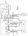
- FIG. 1 is a schematic plan view an adjustable pedal system of the invention comprising an accelerator pedal AC and a brake pedal BR which are commonly used in all automobiles.
- This system also includes a clutch pedal CL which is commonly used in an automobile with a manual transmission.
- These pedals control the engine throttle, the vehicle brakes and the clutch through suitable linkages that are not shown because any suitable linkage may be used.
- the pedals in turn are all controlled by foot and leg movements of the vehicle driver. The positioning of the pedals with respect to the driver is important to the comfort of the driver.
- the adjustable pedal system allows the driver to position the pedals fore and aft for greater comfort and for greater distance from a steering wheel mounted air bag.
- Pedal adjustment in the system of the invention is done by a single electric motor 1 that drives jack screw actuators 2, 3 and 4 with flexible, but torsionally rigid, cables 5, 6 and 7 as shown in figure 1.
- Motor 1 and jack screw operators 2, 3 and 4 are mounted on a support SP that may be part of a vehicle body or a bracket attached to the vehicle body.
- Each pedal is adjusted by one of the jack screw actuators which is turn is driven by at least one of the flexible cables.
- accelerator pedal AC is adjusted by jack screw actuator 2 which in turn is driven by cable 5 which in turn is driven directly by motor 1.
- clutch pedal CL is adjusted by jack screw actuator 4 which is driven by cable 7 which in turn is indirectly driven by motor 1 via actuators 2 and 3 and cables 5 and 6.
- Motor 1 could be replaced by a motor having a drive shaft at each end and repositioned, for instance between actuators 2 and 3 thereby shortening the drive line to actuator 4.
- each pedal is driven by its own actuator which in turn is driven by at least one cable.
- Jack screw actuators are well know in the art and need not be described in detail. Suffice it to state that each jack screw actuator has a nut N that is translated fore or aft with respect to the screw when the screw S is rotated one way or the other.
- Pedals AC, BR, and CL are pivotally mounted on the nuts N of the respective jack screw actuators 2, 3 and 4 so that the three pedals move fore or aft in unison when jack screw actuators 2, 3 and 4 are driven by the common electric motor 1.
- the adjustable pedal system of the invention maintains the fore-aft alignment of the various pedals by controlling the electric motor 1 with a normally closed switch that is mechanically connected to the adjustable pedals; the switch being opened when the adjustable pedals are out of alignment to de-energize the electric motor 1. This feature prevents pedal misalignment during the adjustment process even if one of the drive cables breaks so that one of the pedals is not moved by its associated jack screw actuator during the adjustment process.
- the switch is part of a switch assembly A that comprises slides 8 and 9 inside a housing 10 that has two conducting rails 11 and 12 as best shown in figures 2 and 3.
- Slides 8 and 9 have conducting portions 8a and 9a respectively that engage conducting rails 11 and 12 respectively. Conducting portions 8a and 9a also contact each other when slides 8 and 9 are aligned as shown in figure 2.
- Slides 8 and 9 move side-by-side in housing 10. Slides 8 and 9 are mechanically connected to the respective translatable nuts N of jack screw actuators 2 and 4 by pull cables 13 and 14 respectively. Slides 8 and 9 are spring biased toward a closed end of housing 10 by respective coil return springs 15 and 16 that are arranged on parallel centerlines in housing 10. During normal operation, slides 8 and 9 are pulled away from the closed end of housing 10 in unison as the pedals 2, 3 and 4 are moved in unison toward the driver by electric motor 1 during the adjustment process. Conducting portions 8a and 9a contact each other and the respective conducting rails 11 and 12 thus maintaining the motor control circuit shown in figure 1 closed after an on-off pedal position adjustment switch 18 has been closed for the adjustment process.
- the modified system includes a memory circuit 22 in addition to the components of the system shown in figures 1, 2 and 3.
- the common components of the two systems are identified by the same numerals.
- the memory circuit 22 includes an electrical power source such as a battery 24 and a pedal memory module 26 that receives and processes a memory control signal that is generated by a potentiometer P that is associated with switch assembly A that shuts down motor 1 when pedal misalignment requires a shut down as explained above.
- potentiometer P is incorporated in switch assembly A as shown in figure 5.
- Switch assembly cover 28 has a resistive strip 29 and a parallel laterally spaced conducting rail 30 glued or otherwise suitably secured to an inner surface of cover 28.
- Slide 9 carries a contact brush 27.
- pedals AC, BR and CL are adjusted fore and aft contact brush 27 slides on resistive strip 29 and conducting rail 30 changing the working length and the voltage signal of the potentiometer in accordance with the fore and aft position of the pedals AC and CL.
- Potentiometer P feeds the voltage signal into the pedal memory module 26 where various settings are or can be stored. The input voltage signal is then processed and compared with the stored settings to produce an output signal which includes a indicating component and/or a control component.
- the indicating component can be used to operate a signal light or horn 32 indicating a particular driver's preferred pedal position has been achieved.
- the control component can be used to shut the motor 1 down for instance by opening a normally closed switch 33 in the motor control circuit or operating a relay switch in a conventional motor control circuit.
- the pedals AC, BR and CL are pivotally to the nuts N of the respective jack screws 2, 3 and 4 by lever arms forming part of the respective pedal.
- the pedals can be immovable fixed to the nuts N depending on the mechanism that adjusts the positions of the pedals. See for instance, the Rixon '302 patent discussed above.
- the terms used herein are merely descriptive, rather than limiting, and that various changes may be made without departing from the scope and spirit of the invention.
Applications Claiming Priority (4)
| Application Number | Priority Date | Filing Date | Title |
|---|---|---|---|
| US15575099P | 1999-09-23 | 1999-09-23 | |
| US155750P | 1999-09-23 | ||
| US09/640,384 US6450061B1 (en) | 1999-09-23 | 2000-08-16 | Adjustable pedal system with misalignment sensor |
| US640384 | 2000-08-16 |
Publications (2)
| Publication Number | Publication Date |
|---|---|
| EP1087283A2 true EP1087283A2 (fr) | 2001-03-28 |
| EP1087283A3 EP1087283A3 (fr) | 2002-01-23 |
Family
ID=26852588
Family Applications (1)
| Application Number | Title | Priority Date | Filing Date |
|---|---|---|---|
| EP00203219A Withdrawn EP1087283A3 (fr) | 1999-09-23 | 2000-09-15 | Ensemble de pédales réglables en position avec capteur de désalignement |
Country Status (2)
| Country | Link |
|---|---|
| US (1) | US6450061B1 (fr) |
| EP (1) | EP1087283A3 (fr) |
Families Citing this family (18)
| Publication number | Priority date | Publication date | Assignee | Title |
|---|---|---|---|---|
| US6352007B1 (en) * | 2000-01-27 | 2002-03-05 | Dura Global Technologies | Control system for adjustable pedal assembly |
| US6766713B2 (en) * | 2000-01-27 | 2004-07-27 | Dura Global Technologies, Inc. | Control system for adjustable pedal assembly having individual motor drives |
| DE10012179A1 (de) * | 2000-03-13 | 2001-10-04 | Methode Electronics Malta Ltd | Pedaleinrichtung für ein Kraftfahrzeug mit einer wegaufnehmenden Sensoreinheit |
| US6732035B2 (en) * | 2000-10-11 | 2004-05-04 | Daimlerchrysler Corporation | Adjustable pedal assembly for a motor vehicle with a safety feature |
| FR2821178B1 (fr) * | 2001-02-19 | 2003-04-25 | Peugeot Citroen Automobiles Sa | Pedale de frein destinee a equiper un vehicule automobile |
| FR2821177B1 (fr) * | 2001-02-19 | 2003-04-25 | Peugeot Citroen Automobiles Sa | Pedale d'embrayage destinee a equiper un vehicule |
| FR2821179B1 (fr) * | 2001-02-19 | 2003-04-25 | Peugeot Citroen Automobiles Sa | Repose-pied pour vehicule automobile |
| US6595082B2 (en) * | 2001-07-03 | 2003-07-22 | Delphi Technologies, Inc. | Adjustable pedal system with fail-safe device |
| US6862950B2 (en) * | 2001-11-02 | 2005-03-08 | Ksr Industrial Corporation | Adjustable pedal assembly |
| US7191680B2 (en) | 2002-01-01 | 2007-03-20 | Drivesol Worldwide, Inc. | Stepping motor direct drive adjustable pedal assembly |
| US20030121354A1 (en) | 2002-01-01 | 2003-07-03 | Christopher Rixon | Stepping motor direct drive adjustable pedal assembly |
| DE10254585A1 (de) * | 2002-11-22 | 2004-06-09 | Fico Cables, S.A., Rubi | Pedal mit verstellbarer Position |
| US20040244527A1 (en) * | 2003-06-09 | 2004-12-09 | Christopher Rixon | Direct drive adjustable pedal system with step-over control |
| US7270028B2 (en) * | 2004-02-03 | 2007-09-18 | Drivesol Worldwide, Inc. | Adjustable pedal assembly with step-over control |
| US7681474B2 (en) * | 2004-10-21 | 2010-03-23 | Continental Automotive Systems Us, Inc. | System for adjusting the pedals of a vehicle |
| WO2008052051A2 (fr) * | 2006-10-24 | 2008-05-02 | Goodrich Corporation | Unité de mesure d'actionnement de frein d'avion |
| US8069750B2 (en) | 2007-08-09 | 2011-12-06 | Ksr Technologies Co. | Compact pedal assembly with improved noise control |
| US11036252B1 (en) | 2020-01-10 | 2021-06-15 | Nio Usa, Inc. | Pedal assembly for a motor vehicle |
Citations (3)
| Publication number | Priority date | Publication date | Assignee | Title |
|---|---|---|---|---|
| US4870871A (en) | 1987-05-22 | 1989-10-03 | Wickes Manufacturing Company | Adjustable accelerator and brake pedal mechanism |
| US5460061A (en) | 1993-09-17 | 1995-10-24 | Comfort Pedals, Inc. | Adjustable control pedal apparatus |
| US5722302A (en) | 1995-08-09 | 1998-03-03 | Teleflex, Inc. | Adjustable pedal assembly |
Family Cites Families (10)
| Publication number | Priority date | Publication date | Assignee | Title |
|---|---|---|---|---|
| US3643525A (en) | 1970-05-26 | 1972-02-22 | Gen Motors Corp | Adjustable control pedals for vehicles |
| US5351573A (en) * | 1991-10-07 | 1994-10-04 | Cicotte Edmond B | Adjustable automobile pedal system |
| US5632183A (en) * | 1995-08-09 | 1997-05-27 | Comfort Pedals, Inc. | Adjustable pedal assembly |
| US5819593A (en) * | 1995-08-09 | 1998-10-13 | Comcorp Technologies, Inc. | Electronic adjustable pedal assembly |
| US5722301A (en) | 1996-07-08 | 1998-03-03 | Vps Control Systems, Inc. | Push-pull blade control with deflectable end rod |
| SE518099C2 (sv) * | 1997-11-21 | 2002-08-27 | Claes Johansson Automotive Ab | Inställbart pedalställ för ett fordon |
| US6189409B1 (en) * | 1999-01-11 | 2001-02-20 | Daimlerchrysler Corporation | Adjustable pedal system |
| US6324939B1 (en) * | 1999-02-14 | 2001-12-04 | Edmond B. Cicotte | Adjustable automobile pedal system |
| DE19947500A1 (de) | 1999-10-01 | 2001-05-03 | Continental Teves Ag & Co Ohg | Vorrichtung und Verfahren zum elektromotorischen Verstellen einer Betätigungsvorrichtung |
| US6352007B1 (en) | 2000-01-27 | 2002-03-05 | Dura Global Technologies | Control system for adjustable pedal assembly |
-
2000
- 2000-08-16 US US09/640,384 patent/US6450061B1/en not_active Expired - Fee Related
- 2000-09-15 EP EP00203219A patent/EP1087283A3/fr not_active Withdrawn
Patent Citations (3)
| Publication number | Priority date | Publication date | Assignee | Title |
|---|---|---|---|---|
| US4870871A (en) | 1987-05-22 | 1989-10-03 | Wickes Manufacturing Company | Adjustable accelerator and brake pedal mechanism |
| US5460061A (en) | 1993-09-17 | 1995-10-24 | Comfort Pedals, Inc. | Adjustable control pedal apparatus |
| US5722302A (en) | 1995-08-09 | 1998-03-03 | Teleflex, Inc. | Adjustable pedal assembly |
Also Published As
| Publication number | Publication date |
|---|---|
| EP1087283A3 (fr) | 2002-01-23 |
| US6450061B1 (en) | 2002-09-17 |
Similar Documents
| Publication | Publication Date | Title |
|---|---|---|
| US6450061B1 (en) | Adjustable pedal system with misalignment sensor | |
| US5996438A (en) | Adjustable accelerator pedal | |
| US5823064A (en) | Adjustable automobile pedal system | |
| US7047837B2 (en) | Vehicle pedal device wherein non-operated position of operating portion is adjustable in longitudinal direction of vehicle | |
| US6520045B2 (en) | Vehicle pedal device assembly including two pedals whose non-operated positions are adjustable in vehicle longitudinal direction | |
| US5460061A (en) | Adjustable control pedal apparatus | |
| US6701799B2 (en) | Adjustable automobile pedal system | |
| US6584871B2 (en) | Adjustable pedal assembly | |
| US6840130B2 (en) | Adjustable brake, clutch and accelerator pedals | |
| ATE354823T1 (de) | Kontrollsystem für positionierbare pedaleinheit | |
| US3765264A (en) | Adjustable linkage | |
| US6321617B1 (en) | Adjustable pedal assembly | |
| US6247381B1 (en) | Adjustable brake, clutch and accelerator pedals | |
| US5259349A (en) | Device for the adjustment of a throttle valve | |
| EP1028364A2 (fr) | Système de pédale réglable pour automobile | |
| US6609438B1 (en) | Electric adjustable pedal system with two-piece upper arm | |
| US6267192B1 (en) | Reversing system for a motorcycle | |
| US20020096011A1 (en) | Adjustable pedal system with pedal step over retention | |
| US6536300B1 (en) | Adjustable foot pedal apparatus | |
| US6595082B2 (en) | Adjustable pedal system with fail-safe device | |
| EP1571064B1 (fr) | Ensemble de pédale et de colonne de direction réglable | |
| US20020023516A1 (en) | Adjustable foot-operated control mechanism | |
| AU685315B2 (en) | Adjustable automobile pedal system | |
| EP1428094B1 (fr) | Pedale de commande de vehicule reglable | |
| US7228757B2 (en) | Adjustable foot pedal assembly |
Legal Events
| Date | Code | Title | Description |
|---|---|---|---|
| PUAI | Public reference made under article 153(3) epc to a published international application that has entered the european phase |
Free format text: ORIGINAL CODE: 0009012 |
|
| AK | Designated contracting states |
Kind code of ref document: A2 Designated state(s): AT BE CH CY DE DK ES FI FR GB GR IE IT LI LU MC NL PT SE |
|
| AX | Request for extension of the european patent |
Free format text: AL;LT;LV;MK;RO;SI |
|
| PUAL | Search report despatched |
Free format text: ORIGINAL CODE: 0009013 |
|
| AK | Designated contracting states |
Kind code of ref document: A3 Designated state(s): AT BE CH CY DE DK ES FI FR GB GR IE IT LI LU MC NL PT SE |
|
| AX | Request for extension of the european patent |
Free format text: AL;LT;LV;MK;RO;SI |
|
| AKX | Designation fees paid | ||
| REG | Reference to a national code |
Ref country code: DE Ref legal event code: 8566 |
|
| STAA | Information on the status of an ep patent application or granted ep patent |
Free format text: STATUS: THE APPLICATION IS DEEMED TO BE WITHDRAWN |
|
| 18D | Application deemed to be withdrawn |
Effective date: 20020724 |