EP1087102A2 - Gas turbine bucket with impingement cooled platform - Google Patents
Gas turbine bucket with impingement cooled platform Download PDFInfo
- Publication number
- EP1087102A2 EP1087102A2 EP00305769A EP00305769A EP1087102A2 EP 1087102 A2 EP1087102 A2 EP 1087102A2 EP 00305769 A EP00305769 A EP 00305769A EP 00305769 A EP00305769 A EP 00305769A EP 1087102 A2 EP1087102 A2 EP 1087102A2
- Authority
- EP
- European Patent Office
- Prior art keywords
- platform
- bore
- root portion
- tube
- airfoil
- Prior art date
- Legal status (The legal status is an assumption and is not a legal conclusion. Google has not performed a legal analysis and makes no representation as to the accuracy of the status listed.)
- Granted
Links
Images
Classifications
-
- F—MECHANICAL ENGINEERING; LIGHTING; HEATING; WEAPONS; BLASTING
- F01—MACHINES OR ENGINES IN GENERAL; ENGINE PLANTS IN GENERAL; STEAM ENGINES
- F01D—NON-POSITIVE DISPLACEMENT MACHINES OR ENGINES, e.g. STEAM TURBINES
- F01D5/00—Blades; Blade-carrying members; Heating, heat-insulating, cooling or antivibration means on the blades or the members
- F01D5/12—Blades
- F01D5/14—Form or construction
- F01D5/18—Hollow blades, i.e. blades with cooling or heating channels or cavities; Heating, heat-insulating or cooling means on blades
- F01D5/187—Convection cooling
-
- F—MECHANICAL ENGINEERING; LIGHTING; HEATING; WEAPONS; BLASTING
- F02—COMBUSTION ENGINES; HOT-GAS OR COMBUSTION-PRODUCT ENGINE PLANTS
- F02C—GAS-TURBINE PLANTS; AIR INTAKES FOR JET-PROPULSION PLANTS; CONTROLLING FUEL SUPPLY IN AIR-BREATHING JET-PROPULSION PLANTS
- F02C7/00—Features, components parts, details or accessories, not provided for in, or of interest apart form groups F02C1/00 - F02C6/00; Air intakes for jet-propulsion plants
- F02C7/12—Cooling of plants
-
- F—MECHANICAL ENGINEERING; LIGHTING; HEATING; WEAPONS; BLASTING
- F01—MACHINES OR ENGINES IN GENERAL; ENGINE PLANTS IN GENERAL; STEAM ENGINES
- F01D—NON-POSITIVE DISPLACEMENT MACHINES OR ENGINES, e.g. STEAM TURBINES
- F01D25/00—Component parts, details, or accessories, not provided for in, or of interest apart from, other groups
- F01D25/08—Cooling; Heating; Heat-insulation
- F01D25/12—Cooling
-
- F—MECHANICAL ENGINEERING; LIGHTING; HEATING; WEAPONS; BLASTING
- F01—MACHINES OR ENGINES IN GENERAL; ENGINE PLANTS IN GENERAL; STEAM ENGINES
- F01D—NON-POSITIVE DISPLACEMENT MACHINES OR ENGINES, e.g. STEAM TURBINES
- F01D5/00—Blades; Blade-carrying members; Heating, heat-insulating, cooling or antivibration means on the blades or the members
- F01D5/02—Blade-carrying members, e.g. rotors
- F01D5/08—Heating, heat-insulating or cooling means
-
- F—MECHANICAL ENGINEERING; LIGHTING; HEATING; WEAPONS; BLASTING
- F05—INDEXING SCHEMES RELATING TO ENGINES OR PUMPS IN VARIOUS SUBCLASSES OF CLASSES F01-F04
- F05D—INDEXING SCHEME FOR ASPECTS RELATING TO NON-POSITIVE-DISPLACEMENT MACHINES OR ENGINES, GAS-TURBINES OR JET-PROPULSION PLANTS
- F05D2240/00—Components
- F05D2240/80—Platforms for stationary or moving blades
- F05D2240/81—Cooled platforms
-
- Y—GENERAL TAGGING OF NEW TECHNOLOGICAL DEVELOPMENTS; GENERAL TAGGING OF CROSS-SECTIONAL TECHNOLOGIES SPANNING OVER SEVERAL SECTIONS OF THE IPC; TECHNICAL SUBJECTS COVERED BY FORMER USPC CROSS-REFERENCE ART COLLECTIONS [XRACs] AND DIGESTS
- Y02—TECHNOLOGIES OR APPLICATIONS FOR MITIGATION OR ADAPTATION AGAINST CLIMATE CHANGE
- Y02T—CLIMATE CHANGE MITIGATION TECHNOLOGIES RELATED TO TRANSPORTATION
- Y02T50/00—Aeronautics or air transport
- Y02T50/60—Efficient propulsion technologies, e.g. for aircraft
Definitions
- This invention relates to the cooling of turbine buckets and, specifically, to the cooling of the platform region of the bucket, at the base of the airfoil.
- Stage one and stage two buckets in gas turbines experience high temperatures and stress, creating low cycle fatigue life concerns, particularly at the leading edge fillet where the airfoil joins the platform at the forward portion of the pressure side of the airfoil.
- the bucket platforms are cooled by air entering the cavity below the platform, but this arrangement is not completely satisfactory, particularly in connection with the leading edge fillet.
- This invention provides a unique solution to the above problem by directing cooling air through a tube, the forward end of which is located closely adjacent the underside of the platform, below the forward portion of the pressure side of the airfoil, so as to effectively impingement cool the platform in the localized region below the leading edge fillet.
- film cooling holes are formed in the platform itself so that air introduced into the cavity by the impingement cooling tube can escape the cavity and flow along the upper surface of the platform along the contour of the pressure side of the airfoil, in a direction toward the trailing edge of the airfoil.
- the invention in its broader aspects, relates to a turbine bucket having an airfoil portion and a root portion, with a substantially planar platform at an interface between the airfoil portion and root portion, a platform cooling arrangement comprising at least one bore in the root portion and at least one impingement cooling tube seated in the bore, the tube extending beyond the bore with an outlet in close proximity to a targeted area on an underside of the platform.
- the invention in another aspect, relates to a method of cooling a leading edge fillet region of a turbine bucket having an airfoil portion and a root portion, the airfoil portion joined to a platform extending over the root portion, comprising: a) providing a through bore in a leading side of a cover plate in the root portion, the bore communicating with a recess in the root portion underlying the airfoil portion; b) inserting a tube in the bore, with a tip of the tube extending beyond the bore and in close proximity to a targeted area on an underside of the platform; c) supplying cooling air to the recess via the tube such that the targeted area is impingement cooled by the cooling air passing through the tube.
- a turbine bucket 10 includes an airfoil portion 12 extending vertically upwardly from a horizontal, substantially planar platform 14.
- the airfoil portion has a leading edge 15 and a trailing edge 17.
- the platform 14 is joined with the cover plate 24.
- Cooling passages extend in radially outward and inward directions in a serpentine path through the airfoil portion, the path having passages in the root portion communicating with supply and return passages 28, 30 in the dovetail.
- the internal airfoil cooling circuit forms no part of the invention, however, and is therefore not shown in detail.
- the substantially hollow space or recess 32 in the root portion above the dovetail 26 but below the platform 14, defined further by the sides 20, 22 of the cover plate.
- This recess is generally on the pressure side 34 of the airfoil, and it will be appreciated from Figure 3 that a relatively large portion of the platform 14 on the pressure side 34 of the airfoil overlies the hollow space or recess 32.
- An angled hole 36 is drilled through the leading side 20 of the cover plate 24 from the lower end of the root portion, on the external side thereof, extending upwardly (i.e., substantially radially) and opening into the recess 32. Due to the angled orientation, the hole 36 has an exit profile on the interior of the root wall 38 which is elliptical in shape as shown in Figure 2.
- An impingement cooling tube 40 is pressed into the hole 36 from under the root portion, so that an outlet at the upper end or tip 42 of the tube is located close to the underside of the platform, and close to a targeted area along the leading edge fillet 44 where the airfoil joins the platform.
- the lower end of the tube 40 is flared at 46 to limit the extent of insertion, and the tube may be fixed in place by a spot weld at 47 to prevent the tube from sliding back through the hole in a direction opposite the assembly direction.
- the tube end 42 is within about 0.5" from the underside of the platform.
- a second hole 48 is drilled from the leading side 20 of the cover plate 24 so as to intersect with the hole 36, just below the lower end of the tube 40. In this way, rotor or wheel space purge air can enter the tube 40 via hole 36.
- an array of film cooling holes 50 extend through the platform 14 from the recess 32 to a location on the external side of the platform.
- Another feature of the invention lies in the combination of the above described impingement cooling with film cooling along the upper surface of the platform. This is achieved by utilizing the array of film cooling holes 50 in the platform, allowing the cooling air in the hollow space 32 to exit along the top surface of the platform.
- the film cooling holes 50 are directionally oriented so that the cooling air merges with the gas path air and flows along the pressure side of the airfoil toward the trailing edge 17.
- the flowpath of the film cooling air is such that it can carry over to the suction side of the platform of the adjacent bucket, increasing the overall effectiveness of the system.
- the underside of the platform 14 can be provided with any suitable rough coat, thus increasing the surface area available for heat transfer.
- one or more additional impingement cooling tubes may be used in conjunction with the tube 40 to enhance heat transfer at targeted locations along the underside of the platform.
Abstract
Description
- This invention relates to the cooling of turbine buckets and, specifically, to the cooling of the platform region of the bucket, at the base of the airfoil.
- Stage one and stage two buckets in gas turbines experience high temperatures and stress, creating low cycle fatigue life concerns, particularly at the leading edge fillet where the airfoil joins the platform at the forward portion of the pressure side of the airfoil.
- In aircraft engines, the bucket platforms are cooled by air entering the cavity below the platform, but this arrangement is not completely satisfactory, particularly in connection with the leading edge fillet.
- This invention provides a unique solution to the above problem by directing cooling air through a tube, the forward end of which is located closely adjacent the underside of the platform, below the forward portion of the pressure side of the airfoil, so as to effectively impingement cool the platform in the localized region below the leading edge fillet.
- In addition, film cooling holes are formed in the platform itself so that air introduced into the cavity by the impingement cooling tube can escape the cavity and flow along the upper surface of the platform along the contour of the pressure side of the airfoil, in a direction toward the trailing edge of the airfoil.
- In its broader aspects, the invention relates to a turbine bucket having an airfoil portion and a root portion, with a substantially planar platform at an interface between the airfoil portion and root portion, a platform cooling arrangement comprising at least one bore in the root portion and at least one impingement cooling tube seated in the bore, the tube extending beyond the bore with an outlet in close proximity to a targeted area on an underside of the platform.
- In another aspect, the invention relates to a method of cooling a leading edge fillet region of a turbine bucket having an airfoil portion and a root portion, the airfoil portion joined to a platform extending over the root portion, comprising: a) providing a through bore in a leading side of a cover plate in the root portion, the bore communicating with a recess in the root portion underlying the airfoil portion; b) inserting a tube in the bore, with a tip of the tube extending beyond the bore and in close proximity to a targeted area on an underside of the platform; c) supplying cooling air to the recess via the tube such that the targeted area is impingement cooled by the cooling air passing through the tube.
- The invention will now be described in greater detail by way of example, with reference to the drawings in which:
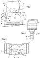
- Figure 1 is a partial side cross section of a bucket in accordance with the invention;
- Figure 2 is a partial end view of a lower dovetail portion (of the leading side edge) of the bucket not entirely shown in Figure 1; and
- Figure 3 is a top plan view of the bucket in accordance with the invention.
-
- With reference to Figures 1-3, a
turbine bucket 10 includes anairfoil portion 12 extending vertically upwardly from a horizontal, substantiallyplanar platform 14. The airfoil portion has a leadingedge 15 and atrailing edge 17. Below theplatform 14, there are two pair of so-called "angel wings" 16, 18 extending in opposite directions from the leading and trailingsides cover plate 24 in the root portion of the bucket. Theplatform 14 is joined with thecover plate 24. Below the root portion, there is adovetail 26 by which the bucket is secured to a turbine wheel (in a preferred embodiment, the stage 1 or stage 2 wheels of a gas turbine). - Cooling passages (not shown) extend in radially outward and inward directions in a serpentine path through the airfoil portion, the path having passages in the root portion communicating with supply and
return passages dovetail 26 but below theplatform 14, defined further by thesides pressure side 34 of the airfoil, and it will be appreciated from Figure 3 that a relatively large portion of theplatform 14 on thepressure side 34 of the airfoil overlies the hollow space or recess 32. - An
angled hole 36 is drilled through the leadingside 20 of thecover plate 24 from the lower end of the root portion, on the external side thereof, extending upwardly (i.e., substantially radially) and opening into therecess 32. Due to the angled orientation, thehole 36 has an exit profile on the interior of the root wall 38 which is elliptical in shape as shown in Figure 2. Animpingement cooling tube 40 is pressed into thehole 36 from under the root portion, so that an outlet at the upper end ortip 42 of the tube is located close to the underside of the platform, and close to a targeted area along the leadingedge fillet 44 where the airfoil joins the platform. - The lower end of the
tube 40 is flared at 46 to limit the extent of insertion, and the tube may be fixed in place by a spot weld at 47 to prevent the tube from sliding back through the hole in a direction opposite the assembly direction. Preferably, thetube end 42 is within about 0.5" from the underside of the platform. - Since the lower edge of the
cover plate 24 will seat on the wheel surface, thus blocking thehole 36, asecond hole 48 is drilled from the leadingside 20 of thecover plate 24 so as to intersect with thehole 36, just below the lower end of thetube 40. In this way, rotor or wheel space purge air can enter thetube 40 viahole 36. - In addition, an array of
film cooling holes 50 extend through theplatform 14 from therecess 32 to a location on the external side of the platform. - With the above arrangement, purge air from wheel space below the bucket will enter the
hole 48 and flow through thetube 40 so as to impinge directly on the underside of theplatform 14, below but proximate the leadingedge fillet 44. The underside of theplatform 14 is thus impingement cooled in the leading edge fillet area to reduce stress and improve low cycle fatigue margins. Of course, the enhancement of heat transfer in this specific region continues along the platform and at least partially under the airfoil itself. - Another feature of the invention lies in the combination of the above described impingement cooling with film cooling along the upper surface of the platform. This is achieved by utilizing the array of
film cooling holes 50 in the platform, allowing the cooling air in thehollow space 32 to exit along the top surface of the platform. Thefilm cooling holes 50 are directionally oriented so that the cooling air merges with the gas path air and flows along the pressure side of the airfoil toward thetrailing edge 17. The flowpath of the film cooling air is such that it can carry over to the suction side of the platform of the adjacent bucket, increasing the overall effectiveness of the system. - To further enhance heat transfer, the underside of the
platform 14 can be provided with any suitable rough coat, thus increasing the surface area available for heat transfer. In addition, one or more additional impingement cooling tubes may be used in conjunction with thetube 40 to enhance heat transfer at targeted locations along the underside of the platform. - For the sake of good order, various features of the invention are set out in the following clauses:-
- 1. In a turbine bucket having an airfoil portion and a root portion, with
a substantially planar platform at an interface between the airfoil portion and
root portion, a platform cooling arrangement comprising:
- at least one bore in said root portion and at least one impingement cooling tube seated in said at least one bore, said tube extending beyond said bore with an outlet in close proximity to a targeted area on an underside of said platform.
- 2. The bucket of clause 1 wherein said targeted area lies within a recess under said platform, and proximate a leading edge fillet of said airfoil portion.
- 3. The bucket of clause 2 wherein said platform is provided with a plurality of film cooling holes communicating with said recess.
- 4. The bucket of clause 3 wherein said plurality of film cooling holes are located closer to a trailing edge of said airfoil portion than to the leading edge of said airfoil portion.
- 5. The bucket of clause 1 wherein the underside of said platform is coated with a rough coat material.
- 6. The bucket of clause 4 wherein said impingement cooling tube and said plurality of film cooling holes are located on a pressure side of said airfoil portion.
- 7. The bucket of clause 3 wherein said film cooling holes are directionally oriented to cause cooling air to flow in a path generally toward said trailing edge of said airfoil portion.
- 8. The bucket of clause 1 wherein said impingement cooling tube is flared at its rearward end to limit forward insertion into said bore.
- 9. The bucket of clause 1 wherein said impingement cooling tube is secured within said bore so as to prevent movement in a direction away from said platform.
- 10. In a turbine bucket having an airfoil portion and a root portion, with
a substantially planar platform at an interface between the airfoil portion and
root portion, a platform cooling arrangement comprising:
- means for impingement cooling a targeted area on an underside of said platform.
- 11. A method of cooling a leading edge fillet region of a turbine bucket
having an airfoil portion and a root portion, said airfoil portion joined to a
platform extending over said root portion, comprising:
- a) providing a through bore in a leading side of a cover plate in said root portion, said bore communicating with a recess in said root portion underlying said airfoil portion;
- b) inserting a tube in said bore, with a tip of the tube extending beyond said bore and in close proximity to a targeted area on an underside of said platform;
- c) supplying cooling air to said recess via said tube such that said targeted area is impingement cooled by said cooling air passing through said tube.
- 12. The method of clause 11 wherein said targeted area is an area in said recess substantially directly beneath the leading edge fillet of said airfoil portion.
- 13. The method of clause 11 including providing film cooling holes to allow said cooling air to escape from said recess.
- 14. The method of clause 11 wherein said film cooling holes are located in said platform.
- 15. The method of
clause 14 wherein said impingement cooling tube and said film cooling holes are on a pressure side of said airfoil portion. - 16. The method of
clause 15 wherein said film cooling holes are directionally oriented to cause cooling air to flow in a path generally toward said trailing edge of said airfoil portion. -
Claims (10)
- In a turbine bucket having an airfoil portion and a root portion, with a substantially planar platform at an interface between the airfoil portion and root portion, a platform cooling arrangement comprising:at least one bore in said root portion and at least one impingement cooling tube seated in said at least one bore, said tube extending beyond said bore with an outlet in close proximity to a targeted area on an underside of said platform.
- The bucket of claim 1 wherein said targeted area lies within a recess under said platform, and proximate a leading edge fillet of said airfoil portion.
- The bucket of claim 2 wherein said platform is provided with a plurality of film cooling holes communicating with said recess.
- The bucket of claim 3 wherein said plurality of film cooling holes are located closer to a trailing edge of said airfoil portion than to the leading edge of said airfoil portion.
- The bucket of any preceding claim wherein the underside of said platform is coated with a rough coat material.
- In a turbine bucket having an airfoil portion and a root portion, with a substantially planar platform at an interface between the airfoil portion and root portion, a platform cooling arrangement comprising:means for impingement cooling a targeted area on an underside of said platform.
- A method of cooling a leading edge fillet region of a turbine bucket having an airfoil portion and a root portion, said airfoil portion joined to a platform extending over said root portion, comprising:a) providing a through bore in a leading side of a cover plate in said root portion, said bore communicating with a recess in said root portion underlying said airfoil portion;b) inserting a tube in said bore, with a tip of the tube extending beyond said bore and in close proximity to a targeted area on an underside of said platform;c) supplying cooling air to said recess via said tube such that said targeted area is impingement cooled by said cooling air passing through said tube.
- The method of claim 7 wherein said targeted area is an area in said recess substantially directly beneath the leading edge fillet of said airfoil portion.
- The method of claim 7 or 8 including providing film cooling holes to allow said cooling air to escape from said recess.
- The method of claim 7, 8 or 9 wherein said film cooling holes are located in said platform.
Applications Claiming Priority (2)
| Application Number | Priority Date | Filing Date | Title |
|---|---|---|---|
| US40458999A | 1999-09-24 | 1999-09-24 | |
| US404589 | 1999-09-24 |
Publications (3)
| Publication Number | Publication Date |
|---|---|
| EP1087102A2 true EP1087102A2 (en) | 2001-03-28 |
| EP1087102A3 EP1087102A3 (en) | 2004-01-02 |
| EP1087102B1 EP1087102B1 (en) | 2010-09-29 |
Family
ID=23600216
Family Applications (1)
| Application Number | Title | Priority Date | Filing Date |
|---|---|---|---|
| EP00305769A Expired - Lifetime EP1087102B1 (en) | 1999-09-24 | 2000-07-07 | Gas turbine bucket with impingement cooled platform |
Country Status (6)
| Country | Link |
|---|---|
| US (1) | US6431833B2 (en) |
| EP (1) | EP1087102B1 (en) |
| JP (1) | JP4571277B2 (en) |
| KR (1) | KR100592150B1 (en) |
| AT (1) | ATE483098T1 (en) |
| DE (1) | DE60045026D1 (en) |
Cited By (6)
| Publication number | Priority date | Publication date | Assignee | Title |
|---|---|---|---|---|
| WO2002050402A1 (en) * | 2000-12-19 | 2002-06-27 | General Electric Company | Impingement cooling scheme for platform of turbine bucket |
| US7309212B2 (en) | 2005-11-21 | 2007-12-18 | General Electric Company | Gas turbine bucket with cooled platform leading edge and method of cooling platform leading edge |
| US7416391B2 (en) | 2006-02-24 | 2008-08-26 | General Electric Company | Bucket platform cooling circuit and method |
| US7841828B2 (en) | 2006-10-05 | 2010-11-30 | Siemens Energy, Inc. | Turbine airfoil with submerged endwall cooling channel |
| EP1772592A3 (en) * | 2005-10-04 | 2010-12-08 | General Electric Company | Dust resistant platform blade |
| EP3556996A1 (en) * | 2018-04-20 | 2019-10-23 | United Technologies Corporation | Blade with inlet orifice on forward face of root |
Families Citing this family (46)
| Publication number | Priority date | Publication date | Assignee | Title |
|---|---|---|---|---|
| US6805534B1 (en) | 2003-04-23 | 2004-10-19 | General Electric Company | Curved bucket aft shank walls for stress reduction |
| US6945749B2 (en) * | 2003-09-12 | 2005-09-20 | Siemens Westinghouse Power Corporation | Turbine blade platform cooling system |
| US7097417B2 (en) * | 2004-02-09 | 2006-08-29 | Siemens Westinghouse Power Corporation | Cooling system for an airfoil vane |
| US20050220618A1 (en) * | 2004-03-31 | 2005-10-06 | General Electric Company | Counter-bored film-cooling holes and related method |
| US7207775B2 (en) * | 2004-06-03 | 2007-04-24 | General Electric Company | Turbine bucket with optimized cooling circuit |
| US7189063B2 (en) * | 2004-09-02 | 2007-03-13 | General Electric Company | Methods and apparatus for cooling gas turbine engine rotor assemblies |
| US20060056968A1 (en) * | 2004-09-15 | 2006-03-16 | General Electric Company | Apparatus and methods for cooling turbine bucket platforms |
| US7186089B2 (en) * | 2004-11-04 | 2007-03-06 | Siemens Power Generation, Inc. | Cooling system for a platform of a turbine blade |
| US7708525B2 (en) * | 2005-02-17 | 2010-05-04 | United Technologies Corporation | Industrial gas turbine blade assembly |
| US7927073B2 (en) * | 2007-01-04 | 2011-04-19 | Siemens Energy, Inc. | Advanced cooling method for combustion turbine airfoil fillets |
| US8057178B2 (en) * | 2008-09-04 | 2011-11-15 | General Electric Company | Turbine bucket for a turbomachine and method of reducing bow wave effects at a turbine bucket |
| US8382436B2 (en) | 2009-01-06 | 2013-02-26 | General Electric Company | Non-integral turbine blade platforms and systems |
| US8147197B2 (en) * | 2009-03-10 | 2012-04-03 | Honeywell International, Inc. | Turbine blade platform |
| US8210813B2 (en) * | 2009-05-07 | 2012-07-03 | General Electric Company | Method and apparatus for turbine engines |
| US8133024B1 (en) | 2009-06-23 | 2012-03-13 | Florida Turbine Technologies, Inc. | Turbine blade with root corner cooling |
| US8523527B2 (en) * | 2010-03-10 | 2013-09-03 | General Electric Company | Apparatus for cooling a platform of a turbine component |
| US8444381B2 (en) * | 2010-03-26 | 2013-05-21 | General Electric Company | Gas turbine bucket with serpentine cooled platform and related method |
| US8647064B2 (en) | 2010-08-09 | 2014-02-11 | General Electric Company | Bucket assembly cooling apparatus and method for forming the bucket assembly |
| US9416666B2 (en) | 2010-09-09 | 2016-08-16 | General Electric Company | Turbine blade platform cooling systems |
| US8684664B2 (en) | 2010-09-30 | 2014-04-01 | General Electric Company | Apparatus and methods for cooling platform regions of turbine rotor blades |
| US8814517B2 (en) | 2010-09-30 | 2014-08-26 | General Electric Company | Apparatus and methods for cooling platform regions of turbine rotor blades |
| US8777568B2 (en) | 2010-09-30 | 2014-07-15 | General Electric Company | Apparatus and methods for cooling platform regions of turbine rotor blades |
| US8840369B2 (en) | 2010-09-30 | 2014-09-23 | General Electric Company | Apparatus and methods for cooling platform regions of turbine rotor blades |
| US8794921B2 (en) | 2010-09-30 | 2014-08-05 | General Electric Company | Apparatus and methods for cooling platform regions of turbine rotor blades |
| US8851846B2 (en) | 2010-09-30 | 2014-10-07 | General Electric Company | Apparatus and methods for cooling platform regions of turbine rotor blades |
| US8636470B2 (en) * | 2010-10-13 | 2014-01-28 | Honeywell International Inc. | Turbine blades and turbine rotor assemblies |
| US8814518B2 (en) | 2010-10-29 | 2014-08-26 | General Electric Company | Apparatus and methods for cooling platform regions of turbine rotor blades |
| US8636471B2 (en) | 2010-12-20 | 2014-01-28 | General Electric Company | Apparatus and methods for cooling platform regions of turbine rotor blades |
| US8753083B2 (en) | 2011-01-14 | 2014-06-17 | General Electric Company | Curved cooling passages for a turbine component |
| US8734111B2 (en) | 2011-06-27 | 2014-05-27 | General Electric Company | Platform cooling passages and methods for creating platform cooling passages in turbine rotor blades |
| US9366142B2 (en) | 2011-10-28 | 2016-06-14 | General Electric Company | Thermal plug for turbine bucket shank cavity and related method |
| US8840370B2 (en) | 2011-11-04 | 2014-09-23 | General Electric Company | Bucket assembly for turbine system |
| US8858160B2 (en) | 2011-11-04 | 2014-10-14 | General Electric Company | Bucket assembly for turbine system |
| US8870525B2 (en) | 2011-11-04 | 2014-10-28 | General Electric Company | Bucket assembly for turbine system |
| US8893507B2 (en) | 2011-11-04 | 2014-11-25 | General Electric Company | Method for controlling gas turbine rotor temperature during periods of extended downtime |
| US8845289B2 (en) | 2011-11-04 | 2014-09-30 | General Electric Company | Bucket assembly for turbine system |
| US9022735B2 (en) | 2011-11-08 | 2015-05-05 | General Electric Company | Turbomachine component and method of connecting cooling circuits of a turbomachine component |
| US9127560B2 (en) | 2011-12-01 | 2015-09-08 | General Electric Company | Cooled turbine blade and method for cooling a turbine blade |
| US9243503B2 (en) * | 2012-05-23 | 2016-01-26 | General Electric Company | Components with microchannel cooled platforms and fillets and methods of manufacture |
| US10180067B2 (en) | 2012-05-31 | 2019-01-15 | United Technologies Corporation | Mate face cooling holes for gas turbine engine component |
| US9121292B2 (en) | 2012-12-05 | 2015-09-01 | General Electric Company | Airfoil and a method for cooling an airfoil platform |
| WO2014186005A2 (en) | 2013-02-15 | 2014-11-20 | United Technologies Corporation | Gas turbine engine component with combined mate face and platform cooling |
| US9810070B2 (en) | 2013-05-15 | 2017-11-07 | General Electric Company | Turbine rotor blade for a turbine section of a gas turbine |
| US9982542B2 (en) * | 2014-07-21 | 2018-05-29 | United Technologies Corporation | Airfoil platform impingement cooling holes |
| US11286809B2 (en) * | 2017-04-25 | 2022-03-29 | Raytheon Technologies Corporation | Airfoil platform cooling channels |
| US10968750B2 (en) | 2018-09-04 | 2021-04-06 | General Electric Company | Component for a turbine engine with a hollow pin |
Citations (8)
| Publication number | Priority date | Publication date | Assignee | Title |
|---|---|---|---|---|
| US2931623A (en) * | 1957-05-02 | 1960-04-05 | Orenda Engines Ltd | Gas turbine rotor assembly |
| US3804551A (en) * | 1972-09-01 | 1974-04-16 | Gen Electric | System for the introduction of coolant into open-circuit cooled turbine buckets |
| US3834831A (en) * | 1973-01-23 | 1974-09-10 | Westinghouse Electric Corp | Blade shank cooling arrangement |
| US3950113A (en) * | 1968-10-05 | 1976-04-13 | Daimler-Benz Aktiengesellschaft | Turbine blade |
| US4017213A (en) * | 1975-10-14 | 1977-04-12 | United Technologies Corporation | Turbomachinery vane or blade with cooled platforms |
| US4350473A (en) * | 1980-02-22 | 1982-09-21 | General Electric Company | Liquid cooled counter flow turbine bucket |
| US4946346A (en) * | 1987-09-25 | 1990-08-07 | Kabushiki Kaisha Toshiba | Gas turbine vane |
| US5344283A (en) * | 1993-01-21 | 1994-09-06 | United Technologies Corporation | Turbine vane having dedicated inner platform cooling |
Family Cites Families (19)
| Publication number | Priority date | Publication date | Assignee | Title |
|---|---|---|---|---|
| US3936227A (en) | 1973-08-02 | 1976-02-03 | General Electric Company | Combined coolant feed and dovetailed bucket retainer ring |
| US3967353A (en) | 1974-07-18 | 1976-07-06 | General Electric Company | Gas turbine bucket-root sidewall piece seals |
| US4012167A (en) | 1975-10-14 | 1977-03-15 | United Technologies Corporation | Turbomachinery vane or blade with cooled platforms |
| US4244676A (en) | 1979-06-01 | 1981-01-13 | General Electric Company | Cooling system for a gas turbine using a cylindrical insert having V-shaped notch weirs |
| US4531889A (en) | 1980-08-08 | 1985-07-30 | General Electric Co. | Cooling system utilizing flow resistance devices to distribute liquid coolant to air foil distribution channels |
| JPS63306204A (en) * | 1987-06-08 | 1988-12-14 | Hitachi Ltd | Impingement cooling device |
| JP3110227B2 (en) * | 1993-11-22 | 2000-11-20 | 株式会社東芝 | Turbine cooling blade |
| WO1996006266A1 (en) * | 1994-08-24 | 1996-02-29 | Westinghouse Electric Corporation | Gas turbine blade with cooled platform |
| JPH08240102A (en) * | 1995-03-02 | 1996-09-17 | Mitsubishi Heavy Ind Ltd | Steam cooling blade for gas turbine |
| US5536143A (en) * | 1995-03-31 | 1996-07-16 | General Electric Co. | Closed circuit steam cooled bucket |
| JPH0941903A (en) * | 1995-07-27 | 1997-02-10 | Toshiba Corp | Gas turbine cooling bucket |
| US5800124A (en) * | 1996-04-12 | 1998-09-01 | United Technologies Corporation | Cooled rotor assembly for a turbine engine |
| JP3426841B2 (en) * | 1996-04-15 | 2003-07-14 | 三菱重工業株式会社 | Gas turbine blade |
| US5738489A (en) | 1997-01-03 | 1998-04-14 | General Electric Company | Cooled turbine blade platform |
| JP3500045B2 (en) * | 1997-07-07 | 2004-02-23 | 三菱重工業株式会社 | Steam cooling system for gas turbine blades |
| JP3546135B2 (en) * | 1998-02-23 | 2004-07-21 | 三菱重工業株式会社 | Gas turbine blade platform |
| US6065931A (en) * | 1998-03-05 | 2000-05-23 | Mitsubishi Heavy Industries, Ltd. | Gas turbine moving blade |
| US6176678B1 (en) | 1998-11-06 | 2001-01-23 | General Electric Company | Apparatus and methods for turbine blade cooling |
| US6158962A (en) | 1999-04-30 | 2000-12-12 | General Electric Company | Turbine blade with ribbed platform |
-
2000
- 2000-07-07 AT AT00305769T patent/ATE483098T1/en not_active IP Right Cessation
- 2000-07-07 EP EP00305769A patent/EP1087102B1/en not_active Expired - Lifetime
- 2000-07-07 DE DE60045026T patent/DE60045026D1/en not_active Expired - Lifetime
- 2000-07-11 JP JP2000209173A patent/JP4571277B2/en not_active Expired - Lifetime
- 2000-07-18 KR KR1020000040914A patent/KR100592150B1/en not_active IP Right Cessation
-
2001
- 2001-01-24 US US09/768,220 patent/US6431833B2/en not_active Expired - Lifetime
Patent Citations (8)
| Publication number | Priority date | Publication date | Assignee | Title |
|---|---|---|---|---|
| US2931623A (en) * | 1957-05-02 | 1960-04-05 | Orenda Engines Ltd | Gas turbine rotor assembly |
| US3950113A (en) * | 1968-10-05 | 1976-04-13 | Daimler-Benz Aktiengesellschaft | Turbine blade |
| US3804551A (en) * | 1972-09-01 | 1974-04-16 | Gen Electric | System for the introduction of coolant into open-circuit cooled turbine buckets |
| US3834831A (en) * | 1973-01-23 | 1974-09-10 | Westinghouse Electric Corp | Blade shank cooling arrangement |
| US4017213A (en) * | 1975-10-14 | 1977-04-12 | United Technologies Corporation | Turbomachinery vane or blade with cooled platforms |
| US4350473A (en) * | 1980-02-22 | 1982-09-21 | General Electric Company | Liquid cooled counter flow turbine bucket |
| US4946346A (en) * | 1987-09-25 | 1990-08-07 | Kabushiki Kaisha Toshiba | Gas turbine vane |
| US5344283A (en) * | 1993-01-21 | 1994-09-06 | United Technologies Corporation | Turbine vane having dedicated inner platform cooling |
Cited By (6)
| Publication number | Priority date | Publication date | Assignee | Title |
|---|---|---|---|---|
| WO2002050402A1 (en) * | 2000-12-19 | 2002-06-27 | General Electric Company | Impingement cooling scheme for platform of turbine bucket |
| EP1772592A3 (en) * | 2005-10-04 | 2010-12-08 | General Electric Company | Dust resistant platform blade |
| US7309212B2 (en) | 2005-11-21 | 2007-12-18 | General Electric Company | Gas turbine bucket with cooled platform leading edge and method of cooling platform leading edge |
| US7416391B2 (en) | 2006-02-24 | 2008-08-26 | General Electric Company | Bucket platform cooling circuit and method |
| US7841828B2 (en) | 2006-10-05 | 2010-11-30 | Siemens Energy, Inc. | Turbine airfoil with submerged endwall cooling channel |
| EP3556996A1 (en) * | 2018-04-20 | 2019-10-23 | United Technologies Corporation | Blade with inlet orifice on forward face of root |
Also Published As
| Publication number | Publication date |
|---|---|
| JP4571277B2 (en) | 2010-10-27 |
| US20010019696A1 (en) | 2001-09-06 |
| EP1087102B1 (en) | 2010-09-29 |
| EP1087102A3 (en) | 2004-01-02 |
| DE60045026D1 (en) | 2010-11-11 |
| KR100592150B1 (en) | 2006-06-23 |
| ATE483098T1 (en) | 2010-10-15 |
| KR20010029956A (en) | 2001-04-16 |
| JP2001090501A (en) | 2001-04-03 |
| US6431833B2 (en) | 2002-08-13 |
Similar Documents
| Publication | Publication Date | Title |
|---|---|---|
| EP1087102A2 (en) | Gas turbine bucket with impingement cooled platform | |
| JP5329033B2 (en) | Gas turbine bucket in which the platform leading edge is cooled and method for cooling the platform leading edge | |
| EP1122405B1 (en) | Gas turbine bucket cooling circuit | |
| JP4885200B2 (en) | Gas turbine rotor blade having platform and method for forming the same | |
| US7416391B2 (en) | Bucket platform cooling circuit and method | |
| US8523527B2 (en) | Apparatus for cooling a platform of a turbine component | |
| EP1734228B1 (en) | Tip cap piece for a turbine bucket | |
| JP6030826B2 (en) | Apparatus and method for cooling the platform area of a turbine rotor blade | |
| US5927946A (en) | Turbine blade having recuperative trailing edge tip cooling | |
| US5259730A (en) | Impingement cooled airfoil with bonding foil insert | |
| US5915923A (en) | Gas turbine moving blade | |
| EP1001137B1 (en) | Gas turbine airfoil with axial serpentine cooling circuits | |
| KR101586210B1 (en) | Modular blade or vane for a gas turbine and gas turbine with such a blade or vane | |
| US7645123B1 (en) | Turbine blade with TBC removed from blade tip region | |
| US20060056968A1 (en) | Apparatus and methods for cooling turbine bucket platforms | |
| JP2007327493A (en) | Serpentine cooling circuit and method for cooling shroud | |
| KR20060051506A (en) | Airfoil with large fillet and micro-circuit cooling | |
| KR20050078980A (en) | Micro-circuit platform | |
| JP2014047786A (en) | Cooling arrangement for platform region of turbine rotor blade | |
| EP0541207A1 (en) | Impingement cooled airfoil with bonding foil insert | |
| CN110494628B (en) | Turbine rotor blade with airfoil cooling integrated with impingement platform cooling | |
| CZ20002548A3 (en) | Turbine blade with air-cooled platform and cooling method of the turbine blade leading edge airfoil portion |
Legal Events
| Date | Code | Title | Description |
|---|---|---|---|
| PUAI | Public reference made under article 153(3) epc to a published international application that has entered the european phase |
Free format text: ORIGINAL CODE: 0009012 |
|
| AK | Designated contracting states |
Kind code of ref document: A2 Designated state(s): AT BE CH CY DE DK ES FI FR GB GR IE IT LI LU MC NL PT SE |
|
| AX | Request for extension of the european patent |
Free format text: AL;LT;LV;MK;RO;SI |
|
| PUAL | Search report despatched |
Free format text: ORIGINAL CODE: 0009013 |
|
| AK | Designated contracting states |
Kind code of ref document: A3 Designated state(s): AT BE CH CY DE DK ES FI FR GB GR IE IT LI LU MC NL PT SE |
|
| AX | Request for extension of the european patent |
Extension state: AL LT LV MK RO SI |
|
| 17P | Request for examination filed |
Effective date: 20040702 |
|
| AKX | Designation fees paid |
Designated state(s): AT BE CH CY DE DK ES FI FR GB GR IE IT LI LU MC NL PT SE |
|
| GRAP | Despatch of communication of intention to grant a patent |
Free format text: ORIGINAL CODE: EPIDOSNIGR1 |
|
| GRAJ | Information related to disapproval of communication of intention to grant by the applicant or resumption of examination proceedings by the epo deleted |
Free format text: ORIGINAL CODE: EPIDOSDIGR1 |
|
| GRAP | Despatch of communication of intention to grant a patent |
Free format text: ORIGINAL CODE: EPIDOSNIGR1 |
|
| GRAS | Grant fee paid |
Free format text: ORIGINAL CODE: EPIDOSNIGR3 |
|
| GRAA | (expected) grant |
Free format text: ORIGINAL CODE: 0009210 |
|
| AK | Designated contracting states |
Kind code of ref document: B1 Designated state(s): AT BE CH CY DE DK ES FI FR GB GR IE IT LI LU MC NL PT SE |
|
| REG | Reference to a national code |
Ref country code: GB Ref legal event code: FG4D |
|
| REG | Reference to a national code |
Ref country code: CH Ref legal event code: EP |
|
| REG | Reference to a national code |
Ref country code: CH Ref legal event code: NV Representative=s name: SERVOPATENT GMBH |
|
| REG | Reference to a national code |
Ref country code: IE Ref legal event code: FG4D |
|
| REF | Corresponds to: |
Ref document number: 60045026 Country of ref document: DE Date of ref document: 20101111 Kind code of ref document: P |
|
| PG25 | Lapsed in a contracting state [announced via postgrant information from national office to epo] |
Ref country code: FI Free format text: LAPSE BECAUSE OF FAILURE TO SUBMIT A TRANSLATION OF THE DESCRIPTION OR TO PAY THE FEE WITHIN THE PRESCRIBED TIME-LIMIT Effective date: 20100929 Ref country code: AT Free format text: LAPSE BECAUSE OF FAILURE TO SUBMIT A TRANSLATION OF THE DESCRIPTION OR TO PAY THE FEE WITHIN THE PRESCRIBED TIME-LIMIT Effective date: 20100929 |
|
| REG | Reference to a national code |
Ref country code: NL Ref legal event code: VDEP Effective date: 20100929 |
|
| PG25 | Lapsed in a contracting state [announced via postgrant information from national office to epo] |
Ref country code: GR Free format text: LAPSE BECAUSE OF FAILURE TO SUBMIT A TRANSLATION OF THE DESCRIPTION OR TO PAY THE FEE WITHIN THE PRESCRIBED TIME-LIMIT Effective date: 20101230 Ref country code: SE Free format text: LAPSE BECAUSE OF FAILURE TO SUBMIT A TRANSLATION OF THE DESCRIPTION OR TO PAY THE FEE WITHIN THE PRESCRIBED TIME-LIMIT Effective date: 20100929 |
|
| PG25 | Lapsed in a contracting state [announced via postgrant information from national office to epo] |
Ref country code: NL Free format text: LAPSE BECAUSE OF FAILURE TO SUBMIT A TRANSLATION OF THE DESCRIPTION OR TO PAY THE FEE WITHIN THE PRESCRIBED TIME-LIMIT Effective date: 20100929 Ref country code: PT Free format text: LAPSE BECAUSE OF FAILURE TO SUBMIT A TRANSLATION OF THE DESCRIPTION OR TO PAY THE FEE WITHIN THE PRESCRIBED TIME-LIMIT Effective date: 20110131 Ref country code: IT Free format text: LAPSE BECAUSE OF FAILURE TO SUBMIT A TRANSLATION OF THE DESCRIPTION OR TO PAY THE FEE WITHIN THE PRESCRIBED TIME-LIMIT Effective date: 20100929 |
|
| PG25 | Lapsed in a contracting state [announced via postgrant information from national office to epo] |
Ref country code: BE Free format text: LAPSE BECAUSE OF FAILURE TO SUBMIT A TRANSLATION OF THE DESCRIPTION OR TO PAY THE FEE WITHIN THE PRESCRIBED TIME-LIMIT Effective date: 20100929 |
|
| PG25 | Lapsed in a contracting state [announced via postgrant information from national office to epo] |
Ref country code: ES Free format text: LAPSE BECAUSE OF FAILURE TO SUBMIT A TRANSLATION OF THE DESCRIPTION OR TO PAY THE FEE WITHIN THE PRESCRIBED TIME-LIMIT Effective date: 20110109 |
|
| PLBE | No opposition filed within time limit |
Free format text: ORIGINAL CODE: 0009261 |
|
| STAA | Information on the status of an ep patent application or granted ep patent |
Free format text: STATUS: NO OPPOSITION FILED WITHIN TIME LIMIT |
|
| PG25 | Lapsed in a contracting state [announced via postgrant information from national office to epo] |
Ref country code: DK Free format text: LAPSE BECAUSE OF FAILURE TO SUBMIT A TRANSLATION OF THE DESCRIPTION OR TO PAY THE FEE WITHIN THE PRESCRIBED TIME-LIMIT Effective date: 20100929 |
|
| 26N | No opposition filed |
Effective date: 20110630 |
|
| REG | Reference to a national code |
Ref country code: DE Ref legal event code: R097 Ref document number: 60045026 Country of ref document: DE Effective date: 20110630 |
|
| PG25 | Lapsed in a contracting state [announced via postgrant information from national office to epo] |
Ref country code: MC Free format text: LAPSE BECAUSE OF NON-PAYMENT OF DUE FEES Effective date: 20110731 |
|
| REG | Reference to a national code |
Ref country code: IE Ref legal event code: MM4A |
|
| PG25 | Lapsed in a contracting state [announced via postgrant information from national office to epo] |
Ref country code: IE Free format text: LAPSE BECAUSE OF NON-PAYMENT OF DUE FEES Effective date: 20110707 |
|
| PG25 | Lapsed in a contracting state [announced via postgrant information from national office to epo] |
Ref country code: LU Free format text: LAPSE BECAUSE OF NON-PAYMENT OF DUE FEES Effective date: 20110707 Ref country code: CY Free format text: LAPSE BECAUSE OF EXPIRATION OF PROTECTION Effective date: 20100929 |
|
| PGFP | Annual fee paid to national office [announced via postgrant information from national office to epo] |
Ref country code: FR Payment date: 20130717 Year of fee payment: 14 Ref country code: GB Payment date: 20130729 Year of fee payment: 14 |
|
| GBPC | Gb: european patent ceased through non-payment of renewal fee |
Effective date: 20140707 |
|
| REG | Reference to a national code |
Ref country code: FR Ref legal event code: ST Effective date: 20150331 |
|
| PG25 | Lapsed in a contracting state [announced via postgrant information from national office to epo] |
Ref country code: GB Free format text: LAPSE BECAUSE OF NON-PAYMENT OF DUE FEES Effective date: 20140707 Ref country code: FR Free format text: LAPSE BECAUSE OF NON-PAYMENT OF DUE FEES Effective date: 20140731 |
|
| PGFP | Annual fee paid to national office [announced via postgrant information from national office to epo] |
Ref country code: CH Payment date: 20190624 Year of fee payment: 20 |
|
| PGFP | Annual fee paid to national office [announced via postgrant information from national office to epo] |
Ref country code: DE Payment date: 20190620 Year of fee payment: 20 |
|
| REG | Reference to a national code |
Ref country code: CH Ref legal event code: PCAR Free format text: NEW ADDRESS: WANNERSTRASSE 9/1, 8045 ZUERICH (CH) |
|
| REG | Reference to a national code |
Ref country code: DE Ref legal event code: R071 Ref document number: 60045026 Country of ref document: DE |
|
| REG | Reference to a national code |
Ref country code: CH Ref legal event code: PL |