EP1086859A1 - Structure for mounting cameras on a vehicle - Google Patents
Structure for mounting cameras on a vehicle Download PDFInfo
- Publication number
- EP1086859A1 EP1086859A1 EP00308219A EP00308219A EP1086859A1 EP 1086859 A1 EP1086859 A1 EP 1086859A1 EP 00308219 A EP00308219 A EP 00308219A EP 00308219 A EP00308219 A EP 00308219A EP 1086859 A1 EP1086859 A1 EP 1086859A1
- Authority
- EP
- European Patent Office
- Prior art keywords
- chassis
- cameras
- vehicle
- mounting
- vehicle body
- Prior art date
- Legal status (The legal status is an assumption and is not a legal conclusion. Google has not performed a legal analysis and makes no representation as to the accuracy of the status listed.)
- Granted
Links
Images


Classifications
-
- B—PERFORMING OPERATIONS; TRANSPORTING
- B60—VEHICLES IN GENERAL
- B60R—VEHICLES, VEHICLE FITTINGS, OR VEHICLE PARTS, NOT OTHERWISE PROVIDED FOR
- B60R11/00—Arrangements for holding or mounting articles, not otherwise provided for
- B60R11/04—Mounting of cameras operative during drive; Arrangement of controls thereof relative to the vehicle
-
- G—PHYSICS
- G01—MEASURING; TESTING
- G01C—MEASURING DISTANCES, LEVELS OR BEARINGS; SURVEYING; NAVIGATION; GYROSCOPIC INSTRUMENTS; PHOTOGRAMMETRY OR VIDEOGRAMMETRY
- G01C11/00—Photogrammetry or videogrammetry, e.g. stereogrammetry; Photographic surveying
- G01C11/02—Picture taking arrangements specially adapted for photogrammetry or photographic surveying, e.g. controlling overlapping of pictures
-
- Y—GENERAL TAGGING OF NEW TECHNOLOGICAL DEVELOPMENTS; GENERAL TAGGING OF CROSS-SECTIONAL TECHNOLOGIES SPANNING OVER SEVERAL SECTIONS OF THE IPC; TECHNICAL SUBJECTS COVERED BY FORMER USPC CROSS-REFERENCE ART COLLECTIONS [XRACs] AND DIGESTS
- Y10—TECHNICAL SUBJECTS COVERED BY FORMER USPC
- Y10S—TECHNICAL SUBJECTS COVERED BY FORMER USPC CROSS-REFERENCE ART COLLECTIONS [XRACs] AND DIGESTS
- Y10S224/00—Package and article carriers
- Y10S224/929—Article carrier for electrical device
Definitions
- the present invention relates to a structure for mounting cameras on a vehicle, and more particularly to a mounting structure for cameras which are mounted on a vehicle for obtaining forward environmental data while running in a vehicle drive supporting system.
- a structure described in a publication of Japanese Patent Application Laid-Open No. 11-78717 has been known.
- the publication discloses a structure for mounting a camera inside a front windshield (front glass) of a vehicle, or for mounting a camera as a unit on a room mirror for confirming a rearward direction.
- each position of the both cameras is apt to be relatively tilted because of unavoidable unevenness when manufacturing the front glass and a vehicle body. If each position of cameras is deviated from a correct position thereof, an accuracy of obtained image data may be lowered. As a result, for example, the distance measurement between a car and a forward running car might not be performed accurately, so that the vehicle drive supporting system can not be accurately operated.
- the cameras are independently fixed on the front glass through the stay according to the conventional method, a relative accuracy of an optical axis between the cameras mounted on both sides is apt to change because of vibration caused while running, a distortion of vehicle body, and a temperature difference inside a vehicle, so that the accuracy of obtained image data is lowered.
- a posture such as angle must be adjusted in each camera upon manufacturing, wherein it takes much time to do so. As a result, a productive efficiency thereof is lowered.
- the present invention has been developed in view of the aforementioned problems, and an object of the present invention is to provide a structure for mounting cameras on a vehicle wherein a relative position between cameras disposed on the both sides can be accurately kept even if vibration while running and/or a temperature difference inside a vehicle influences the cameras, so that an accuracy of the obtained image data is not lowered under any situation.
- a first aspect of the present invention is to provide a structure for mounting cameras on a vehicle comprising a chassis having a predetermined length and extended in a lateral direction, a pair of cameras mounted on both sides of a vehicle for making a film of a forward road environment when running, each camera being mounted on both ends of the chassis, and a mounting seat member formed in a center of the chassis, wherein the mounting seat member is fixed onto a predetermined mounting position of a vehicle body so as to mount the pair of cameras on the vehicle body, and portions other than the mounting seat member of the chassis are disposed apart from the vehicle body.
- the two cameras are mounted on the both ends of the chassis, the relative accuracy of each optical axis between the right and left cameras can be prevented from lowering due to vibration when running or temperature difference. Also, since the chassis is fixed onto the vehicle body with a small compressed area, the image data obtained from the both cameras suffers little influence of vibration when running, and the like, so that the reliability of a drive supporting system can be improved.
- a second aspect of the present invention is to provide the structure for mounting cameras on a vehicle according to the first aspect in which a taper plate further intervenes between the mounting seat member and the mounting position on the vehicle body when fixing the chassis onto the mounting position of the vehicle body.
- a third aspect of the present invention is to provide the structure for mounting cameras on a vehicle according to the first aspect in which a plurality of taper plates are further prepared in advance, the taper plates being formed by wedge-like plates with different taper angle when fixing the chassis onto the mounting position of the vehicle body, wherein the taper plate having the most adequate taper angle of the plurality of taper plates intervenes between the mounting seat member and the vehicle body so as to dispose the pair of cameras mounted on the chassis in the predetermined mounting position of the vehicle body.
- the taper plate intervenes between the mounting seat member and a front rail of the vehicle body, it becomes easy to adjust the direction of the optical axis of the right and left cameras, so that a manufacturing efficiency can be improved.
- a fourth aspect of the present invention is to provide the structure for mounting cameras on a vehicle according to the first to third aspects further comprising falling prevention members for engaging the both ends of the chassis with the vehicle body.
- the falling prevention member is provided on the both ends of the chassis, it becomes easy to mount the chassis onto the vehicle body.
- FIG. 1 is an explanatory view of a vehicle drive supporting system using cameras mounted on a vehicle.
- Figs. 2-6 are views showing a mounting structure of cameras on a vehicle according to the present invention.
- the drive supporting system has a pair of charge coupled device cameras (hereinafter called CCD cameras) 10A, 10B for recognizing a forward road environment while running.
- CCD cameras charge coupled device cameras
- An image signal obtained by these CCD cameras 10A, 10B in the vehicle running direction is inputted into an image processing unit 12, wherein the image signal is converted to various kinds of forward data such as distance data.
- the obtained forward data, a road data outputted from a navigation system (not shown), and data of a vehicle running condition are inputted into a preview control unit (hereinafter call PCU) 14.
- the PCU 14 raises an alarm with regard to a distance between the car and a forward running car, and carries out various kinds of control for a drive supporting such as cruise control. Therefore, the high accuracy of the forward data obtained by the CCD cameras 10A, 10B is indispensable for accurately operating the drive supporting system.
- the object of the present invention is to obtain an exact forward data through improving a mounting structure of the CCD cameras 10A, 10B on a vehicle and thereby raising a relative mounting accuracy between the CCD cameras 10A, 10B.
- the mounting structure of cameras of the present invention includes a chassis 16 for mounting the two CCD cameras 10A, 10B inside a vehicle as an important parts.
- the chassis 16 is a member which extends in a lateral direction.
- the CCD cameras 10A, 10B are mounted one on each end of the chassis 16 which is formed by only one material having a high-stiffness and a high-coefficient of thermal conductivity such as an aluminum alloy.
- a mounting seat member 17 for fixing the chassis 16 on a front rail 40 of a vehicle body, which partially extends to the rear of the chassis 16.
- Two pins 18 are attached onto an upper face of the mounting seat member 17.
- the pins 18 are engaged with positioning holes of the front rail 40 so as to position the chassis 16 at a predetermined mounting portion.
- the mounting seat member 17 includes three fixing holes 21 where bolts 42 for fixing the chassis 16 are inserted, as well as the pins 18.
- the mounting seat member 17 is formed with a width of, for example, only about 50mm, and thus an area for mounting the mounting seat member 17 on the front rail 40 is very small.
- a wedge-like taper plate 20 intervenes between the mounting seat member 17 and the front rail 40 as shown in Figs. 2 and 3.
- a plurality of taper plates 20 with different taper angles are prepared in advance so as to enable a vertical angle of an optical axis of the CCD cameras 10A, 10B to change.
- the taper plate 20 there is a taper plate, a front side or a rear side of which is thinly formed, or which is evenly flat.
- a back face of the chassis 16 are mounted connectors 22A, 22B for outputting image data obtained by the right and left CCD cameras 10A, 10B.
- an underside face of the chassis 16 is covered by a circuit cover 24, in which a circuit substrate 26 for controlling each of the CCD cameras 10A, 10B is contained in a space between the chassis 16 and the circuit cover 24.
- the chassis 16 has a hooked sectional shape extending in a lateral direction to prevent the chassis 16 from being transformed due to a weight of the CCD cameras 10A, 10B and/or an acceleration while running.
- the CCD cameras 10A, 10B and the chassis 16 fixed inside a vehicle are covered by an outside cover 27 made of resin, which has engaging portions 28A to be engaged with the chassis 16 at a tip end thereof, and recess portions 28 with a hole where bolts 30 are inserted.
- the outside cover 27 is mounted at a predetermined portion of the front rail 40 through fastening the bolts 30 into the front rail 40.
- the recess portion 28 is covered by a cap 32 after fastening the bolts 30.
- the chassis 16 is supported on the front rail 40 inside a vehicle by the mounting seat member 17.
- falling prevention brackets 34 are attached on an upper portion of both ends of chassis 16, and split pins 36 on an upper end thereof are inserted into holes (not shown) of the front rail 40.
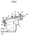
- the falling prevention bracket 34 is formed so as to cover the both upper ends of the chassis 16 as shown from right to left in Fig. 5.
- a front portion 34A of the bracket 34 is connected to a front end portion 16A of the chassis 16 through a belt 38 with U-shape shown in the side view in a vehicle running direction.
- the mounting seat member 17 supports all weight of the chassis 16 including the CCD cameras 10A, 10B after the chassis 16 is fixed to the vehicle through using the taper plate 20. That is, the portions other than the mounting seat member 17 of the chassis 16 are kept under the conditions disposed substantially apart from the vehicle body after being fixed.
- the CCD cameras 10A, 10B are mounted on the both ends of the chassis 16, and the mounting seat member 17 disposed in the center of the chassis 16 is attached with fixing holes (not shown) of the front rail 40 by screwing the three bolts 42, so that the chassis 16 can be fixed onto the front rail 40 with a small compressed area.
- the CCD cameras 10A, 10B suffer little influence of vibration when running and of change of temperature inside a vehicle, so that the accuracy of mounting the both cameras 10A, 10B, i.e. of an optical axis thereof can be maintained. Consequently, the image data of the front environment obtained by the CCD cameras 10A, 10B can be prevented from deteriorating, and the reliability of the driving support system can be improved.
- the most adequate one of a plurality of taper plates 20 is selected and intervenient between the mounting seat member 17 and the front rail 40, so that an angle adjustment of the CCD cameras 10A, 10B can be easily made.
- the chassis 16 supporting the CCD cameras 10A, 10B has enough cross-sectional area, and is formed by a uniform material with high-stiffness and high-coefficient of thermal conductivity. Therefore, a dimensional accuracy between the CCD cameras 10A, 10B is improved, and the thermal conductivity through the chassis 16 is performed quickly, so that there occurs little temperature difference between the CCD cameras 10A, 10B even if daylight is given on only one side, namely a thermal balance between the both cameras can be kept. As a result, an image output characteristic of the right and left CCD cameras is uniform, and the obtained image data is stabilized.
Landscapes
- Engineering & Computer Science (AREA)
- Mechanical Engineering (AREA)
- Multimedia (AREA)
- Physics & Mathematics (AREA)
- General Physics & Mathematics (AREA)
- Radar, Positioning & Navigation (AREA)
- Remote Sensing (AREA)
- Fittings On The Vehicle Exterior For Carrying Loads, And Devices For Holding Or Mounting Articles (AREA)
- Studio Devices (AREA)
- Closed-Circuit Television Systems (AREA)
Abstract
Description
- The present invention relates to a structure for mounting cameras on a vehicle, and more particularly to a mounting structure for cameras which are mounted on a vehicle for obtaining forward environmental data while running in a vehicle drive supporting system.
- In recent years, a vehicle drive supporting system with a camera mounted on a vehicle has been proposed, wherein information for safety is supplied to a driver, or a vehicle control is automatically performed, based on the forward data in a vehicle running direction which are obtained by the camera while running.
- Conventionally, as a mounting structure of a camera mounted on a vehicle, a structure described in a publication of Japanese Patent Application Laid-Open No. 11-78717 has been known. The publication discloses a structure for mounting a camera inside a front windshield (front glass) of a vehicle, or for mounting a camera as a unit on a room mirror for confirming a rearward direction.
- When the mounting structure described in the above-mentioned publication is applied to so-called stereo cameras which have one camera on the right and left sides, respectively, two cameras are mounted on each side of a front glass through a stay. However, in this mounting method, there are problems that each position of the both cameras is apt to be relatively tilted because of unavoidable unevenness when manufacturing the front glass and a vehicle body. If each position of cameras is deviated from a correct position thereof, an accuracy of obtained image data may be lowered. As a result, for example, the distance measurement between a car and a forward running car might not be performed accurately, so that the vehicle drive supporting system can not be accurately operated.
- Furthermore, since the cameras are independently fixed on the front glass through the stay according to the conventional method, a relative accuracy of an optical axis between the cameras mounted on both sides is apt to change because of vibration caused while running, a distortion of vehicle body, and a temperature difference inside a vehicle, so that the accuracy of obtained image data is lowered. In addition, a posture such as angle must be adjusted in each camera upon manufacturing, wherein it takes much time to do so. As a result, a productive efficiency thereof is lowered.
- The present invention has been developed in view of the aforementioned problems, and an object of the present invention is to provide a structure for mounting cameras on a vehicle wherein a relative position between cameras disposed on the both sides can be accurately kept even if vibration while running and/or a temperature difference inside a vehicle influences the cameras, so that an accuracy of the obtained image data is not lowered under any situation.
- A first aspect of the present invention is to provide a structure for mounting cameras on a vehicle comprising a chassis having a predetermined length and extended in a lateral direction, a pair of cameras mounted on both sides of a vehicle for making a film of a forward road environment when running, each camera being mounted on both ends of the chassis, and a mounting seat member formed in a center of the chassis, wherein the mounting seat member is fixed onto a predetermined mounting position of a vehicle body so as to mount the pair of cameras on the vehicle body, and portions other than the mounting seat member of the chassis are disposed apart from the vehicle body.
- According to the above-mentioned constructions, since the two cameras are mounted on the both ends of the chassis, the relative accuracy of each optical axis between the right and left cameras can be prevented from lowering due to vibration when running or temperature difference. Also, since the chassis is fixed onto the vehicle body with a small compressed area, the image data obtained from the both cameras suffers little influence of vibration when running, and the like, so that the reliability of a drive supporting system can be improved.
- A second aspect of the present invention is to provide the structure for mounting cameras on a vehicle according to the first aspect in which a taper plate further intervenes between the mounting seat member and the mounting position on the vehicle body when fixing the chassis onto the mounting position of the vehicle body.
- A third aspect of the present invention is to provide the structure for mounting cameras on a vehicle according to the first aspect in which a plurality of taper plates are further prepared in advance, the taper plates being formed by wedge-like plates with different taper angle when fixing the chassis onto the mounting position of the vehicle body, wherein the taper plate having the most adequate taper angle of the plurality of taper plates intervenes between the mounting seat member and the vehicle body so as to dispose the pair of cameras mounted on the chassis in the predetermined mounting position of the vehicle body.
- According to the above-mentioned second and third constructions, since the taper plate intervenes between the mounting seat member and a front rail of the vehicle body, it becomes easy to adjust the direction of the optical axis of the right and left cameras, so that a manufacturing efficiency can be improved.
- A fourth aspect of the present invention is to provide the structure for mounting cameras on a vehicle according to the first to third aspects further comprising falling prevention members for engaging the both ends of the chassis with the vehicle body.
- According to the above-mentioned fourth construction, since
the falling prevention member is provided on the both ends of the chassis, it becomes easy to mount the chassis onto the vehicle body. - By way of example only, a specific embodiment of the present invention will now be described, with reference to the accompanying drawings, in which:-
- Fig. 1 is an explanatory view showing a vehicle drive supporting system having a mounting structure of cameras on a vehicle according to the present invention;
- Fig. 2 is a front view of a chassis which is an important portion of the mounting structure of cameras on a vehicle according to the present invention;
- Fig. 3 is a sectional view along A-A line of Fig. 2;
- Fig. 4 is a bottom view of the chassis according to the present invention;
- Fig. 5 is a side view of the chassis according to the present invention; and
- Fig. 6 is an exploded perspective view of the mounting structure of cameras on a vehicle according to the present invention.
-
- A preferred embodiment of a mounting structure of cameras on a vehicle to which the present invention is applied will be explained below with reference to the attached drawings.
- FIG. 1 is an explanatory view of a vehicle drive supporting system using cameras mounted on a vehicle. Figs. 2-6 are views showing a mounting structure of cameras on a vehicle according to the present invention.
- First, a summary of the vehicle drive supporting system will be explained hereinafter. The drive supporting system has a pair of charge coupled device cameras (hereinafter called CCD cameras) 10A, 10B for recognizing a forward road environment while running. An image signal obtained by these
CCD cameras image processing unit 12, wherein the image signal is converted to various kinds of forward data such as distance data. - Furthermore, the obtained forward data, a road data outputted from a navigation system (not shown), and data of a vehicle running condition are inputted into a preview control unit (hereinafter call PCU) 14. The PCU 14 raises an alarm with regard to a distance between the car and a forward running car, and carries out various kinds of control for a drive supporting such as cruise control. Therefore, the high accuracy of the forward data obtained by the
CCD cameras CCD cameras CCD cameras - As shown in Fig. 1, the mounting structure of cameras of the present invention includes a
chassis 16 for mounting the twoCCD cameras chassis 16 is a member which extends in a lateral direction. TheCCD cameras chassis 16 which is formed by only one material having a high-stiffness and a high-coefficient of thermal conductivity such as an aluminum alloy. - On the central portion of the
chassis 16 is integrally formed amounting seat member 17 for fixing thechassis 16 on afront rail 40 of a vehicle body, which partially extends to the rear of thechassis 16. Twopins 18 are attached onto an upper face of themounting seat member 17. Thepins 18 are engaged with positioning holes of thefront rail 40 so as to position thechassis 16 at a predetermined mounting portion. As shown in Figs. 1 and 2, themounting seat member 17 includes threefixing holes 21 wherebolts 42 for fixing thechassis 16 are inserted, as well as thepins 18. Themounting seat member 17 is formed with a width of, for example, only about 50mm, and thus an area for mounting themounting seat member 17 on thefront rail 40 is very small. - When the
chassis 16 is fixed on thefront rail 40, a wedge-like taper plate 20 intervenes between themounting seat member 17 and thefront rail 40 as shown in Figs. 2 and 3. A plurality oftaper plates 20 with different taper angles are prepared in advance so as to enable a vertical angle of an optical axis of theCCD cameras taper plate 20, there is a taper plate, a front side or a rear side of which is thinly formed, or which is evenly flat. When fixing thechassis 16, thetaper plate 20 with a most adequate taper angle is selected, so that the optical axis of theCCD cameras chassis 16 can be minutely adjusted so as to be directed into the predetermined correct direction. - As shown in Fig. 1, on a back face of the
chassis 16 are mountedconnectors left CCD cameras chassis 16 is covered by acircuit cover 24, in which acircuit substrate 26 for controlling each of theCCD cameras chassis 16 and thecircuit cover 24. Thechassis 16 has a hooked sectional shape extending in a lateral direction to prevent thechassis 16 from being transformed due to a weight of theCCD cameras - The
CCD cameras chassis 16 fixed inside a vehicle are covered by anoutside cover 27 made of resin, which has engagingportions 28A to be engaged with thechassis 16 at a tip end thereof, and recessportions 28 with a hole wherebolts 30 are inserted. Theoutside cover 27 is mounted at a predetermined portion of thefront rail 40 through fastening thebolts 30 into thefront rail 40. Therecess portion 28 is covered by acap 32 after fastening thebolts 30. - The
chassis 16 is supported on thefront rail 40 inside a vehicle by themounting seat member 17. As shown in Fig. 2, fallingprevention brackets 34 are attached on an upper portion of both ends ofchassis 16, and splitpins 36 on an upper end thereof are inserted into holes (not shown) of thefront rail 40. As shown in Fig. 5, the fallingprevention bracket 34 is formed so as to cover the both upper ends of thechassis 16 as shown from right to left in Fig. 5. Afront portion 34A of thebracket 34 is connected to afront end portion 16A of thechassis 16 through abelt 38 with U-shape shown in the side view in a vehicle running direction. Whereas thebelt 38 prevents thechassis 16 from falling when mounting it, themounting seat member 17 supports all weight of thechassis 16 including theCCD cameras chassis 16 is fixed to the vehicle through using thetaper plate 20. That is, the portions other than the mountingseat member 17 of thechassis 16 are kept under the conditions disposed substantially apart from the vehicle body after being fixed. - As mentioned above and shown in Fig. 6, according to the mounting structure of cameras on a vehicle of the present invention,
theCCD cameras chassis 16, and the mountingseat member 17 disposed in the center of thechassis 16 is attached with fixing holes (not shown) of thefront rail 40 by screwing the threebolts 42, so that thechassis 16 can be fixed onto thefront rail 40 with a small compressed area. - Thus, the
CCD cameras cameras CCD cameras - In addition, according to the present invention, the most adequate one of a plurality of
taper plates 20 is selected and intervenient between the mountingseat member 17 and thefront rail 40, so that an angle adjustment of theCCD cameras - Furthermore, the
chassis 16 supporting theCCD cameras CCD cameras chassis 16 is performed quickly, so that there occurs little temperature difference between theCCD cameras - While there has been described what are at present considered to be preferred embodiments of the present invention, it will be understood that various modifications may be made thereto, and it is intended that the appended claims cover all such modifications as fall within the true spirit and scope of the invention.
Claims (4)
- A structure for mounting cameras on a vehicle, comprising:a chassis having a predetermined length and extending in a lateral direction;a pair of cameras mounted one on each side of a vehicle for detecting an image of a forward road environment when running, each camera being mounted on a respective end of said chassis; anda mounting seat member formed in the center of said chassis;
whereinsaid mounting seat member is fixed onto a predetermined mounting position of a vehicle body so as to mount said pair of cameras on the vehicle body, andportions other than said mounting seat member of the chassis are disposed apart from the vehicle body. - A structure for mounting cameras on a vehicle according to claim 1, further comprising:a taper plate intervenient between said mounting seat member and the mounting position on the vehicle body when fixing said chassis onto the mounting position of the vehicle body.
- A structure for mounting cameras on a vehicle according to claim 1, further comprising:a plurality of preformed taper plates comprising wedge-like plates with different taper angle when fixing said chassis onto the mounting position of the vehicle body,
whereinthe taper plate having the most adequate taper angle of said plurality of taper plates intervenes between said mounting seat member and the vehicle body so as to dispose said pair of cameras mounted on said chassis in the predetermined mounting position of the vehicle body. - A structure for mounting cameras on a vehicle according to any of claims 1 to 3, further comprising:falling prevention members for engaging the both ends of said chassis with the vehicle body.
Applications Claiming Priority (2)
| Application Number | Priority Date | Filing Date | Title |
|---|---|---|---|
| JP26927499A JP3877475B2 (en) | 1999-09-22 | 1999-09-22 | In-vehicle camera mounting structure |
| JP26927499 | 1999-09-22 |
Publications (2)
| Publication Number | Publication Date |
|---|---|
| EP1086859A1 true EP1086859A1 (en) | 2001-03-28 |
| EP1086859B1 EP1086859B1 (en) | 2003-12-17 |
Family
ID=17470082
Family Applications (1)
| Application Number | Title | Priority Date | Filing Date |
|---|---|---|---|
| EP00308219A Expired - Lifetime EP1086859B1 (en) | 1999-09-22 | 2000-09-20 | Structure for mounting cameras on a vehicle |
Country Status (4)
| Country | Link |
|---|---|
| US (1) | US6811330B1 (en) |
| EP (1) | EP1086859B1 (en) |
| JP (1) | JP3877475B2 (en) |
| DE (1) | DE60007249T2 (en) |
Cited By (12)
| Publication number | Priority date | Publication date | Assignee | Title |
|---|---|---|---|---|
| EP1473193A1 (en) * | 2003-04-29 | 2004-11-03 | Robert Bosch Gmbh | Apparatus for cooling a camera |
| DE102005047472B4 (en) * | 2004-10-06 | 2007-05-24 | Honda Motor Co., Ltd. | Structure for attaching a stereo camera to a vehicle |
| US7403709B2 (en) | 2004-10-06 | 2008-07-22 | Honda Motor Co., Ltd. | Structure for attaching stereoscopic camera in vehicle |
| EP1990606A1 (en) * | 2006-02-27 | 2008-11-12 | Matsushita Electric Industrial Co., Ltd. | Stereo camera |
| CN100440934C (en) * | 2004-02-16 | 2008-12-03 | 松下电器产业株式会社 | Operation support device |
| WO2009024430A1 (en) | 2007-08-20 | 2009-02-26 | Continental Automotive Gmbh | Roof module arrangement |
| CN103140379A (en) * | 2010-10-04 | 2013-06-05 | Tk控股公司 | Camera system |
| CN105164549A (en) * | 2013-03-15 | 2015-12-16 | 优步技术公司 | Methods, systems, and apparatus for multi-sensory stereo vision for robots |
| EP3054348A1 (en) * | 2015-02-04 | 2016-08-10 | LG Electronics Inc. | Stereo camera for a vehicle |
| EP3070524A1 (en) * | 2015-03-18 | 2016-09-21 | Ricoh Company, Ltd. | Imaging unit, vehicle control unit and heat transfer method for imaging unit |
| CN105966325A (en) * | 2015-03-12 | 2016-09-28 | 日本电产艾莱希斯株式会社 | Vehicle-mounted camera, method of manufacturing vehicle-mounted camera, and method of manufacturing vehicle body |
| DE102022112320A1 (en) | 2022-05-17 | 2023-11-23 | Audi Aktiengesellschaft | Motor vehicle with an interior mirror arrangement arranged on a windshield |
Families Citing this family (43)
| Publication number | Priority date | Publication date | Assignee | Title |
|---|---|---|---|---|
| US5877897A (en) | 1993-02-26 | 1999-03-02 | Donnelly Corporation | Automatic rearview mirror, vehicle lighting control and vehicle interior monitoring system using a photosensor array |
| US6822563B2 (en) | 1997-09-22 | 2004-11-23 | Donnelly Corporation | Vehicle imaging system with accessory control |
| US6891563B2 (en) | 1996-05-22 | 2005-05-10 | Donnelly Corporation | Vehicular vision system |
| US7655894B2 (en) | 1996-03-25 | 2010-02-02 | Donnelly Corporation | Vehicular image sensing system |
| US6124886A (en) | 1997-08-25 | 2000-09-26 | Donnelly Corporation | Modular rearview mirror assembly |
| US6326613B1 (en) | 1998-01-07 | 2001-12-04 | Donnelly Corporation | Vehicle interior mirror assembly adapted for containing a rain sensor |
| US6445287B1 (en) | 2000-02-28 | 2002-09-03 | Donnelly Corporation | Tire inflation assistance monitoring system |
| US6690268B2 (en) | 2000-03-02 | 2004-02-10 | Donnelly Corporation | Video mirror systems incorporating an accessory module |
| US6278377B1 (en) | 1999-08-25 | 2001-08-21 | Donnelly Corporation | Indicator for vehicle accessory |
| US6420975B1 (en) | 1999-08-25 | 2002-07-16 | Donnelly Corporation | Interior rearview mirror sound processing system |
| JP3565749B2 (en) * | 1999-09-22 | 2004-09-15 | 富士重工業株式会社 | Inspection method of imaging direction of on-vehicle camera and its inspection device |
| US7480149B2 (en) | 2004-08-18 | 2009-01-20 | Donnelly Corporation | Accessory module for vehicle |
| DE10162652A1 (en) * | 2001-12-20 | 2003-07-03 | Bosch Gmbh Robert | Stereo camera arrangement in a motor vehicle |
| WO2003065084A1 (en) | 2002-01-31 | 2003-08-07 | Donnelly Corporation | Vehicle accessory module |
| WO2003093857A2 (en) | 2002-05-03 | 2003-11-13 | Donnelly Corporation | Object detection system for vehicle |
| US7526103B2 (en) | 2004-04-15 | 2009-04-28 | Donnelly Corporation | Imaging system for vehicle |
| US8256821B2 (en) | 2004-12-15 | 2012-09-04 | Magna Donnelly Engineering Gmbh | Accessory module system for a vehicle window |
| DE102006035991A1 (en) * | 2006-08-02 | 2008-02-14 | A. Raymond Et Cie | Device for holding a camera on a support |
| US7972045B2 (en) | 2006-08-11 | 2011-07-05 | Donnelly Corporation | Automatic headlamp control system |
| JP2009068906A (en) * | 2007-09-11 | 2009-04-02 | Panasonic Corp | Distance measuring apparatus |
| JP5324946B2 (en) * | 2008-04-25 | 2013-10-23 | 富士重工業株式会社 | Stereo camera unit |
| US8237855B2 (en) * | 2009-04-16 | 2012-08-07 | Tech-Cast Mfg. Corp. | Camera device capable of synchronously shooting images inside and outside a car |
| JP5628778B2 (en) | 2011-11-30 | 2014-11-19 | 日立オートモティブシステムズ株式会社 | In-vehicle camera mounting device |
| JP5793122B2 (en) | 2012-07-31 | 2015-10-14 | 日立オートモティブシステムズ株式会社 | In-vehicle image processing device |
| DE102013104163A1 (en) * | 2013-04-24 | 2014-10-30 | Conti Temic Microelectronic Gmbh | Stereo Camera System |
| DE102014208487A1 (en) * | 2014-05-07 | 2015-11-12 | Conti Temic Microelectronic Gmbh | Camera of an assistance system of a motor vehicle and method for producing such an assistance system |
| JP2016014564A (en) * | 2014-07-01 | 2016-01-28 | 株式会社リコー | Imaging unit |
| JP6303974B2 (en) | 2014-10-22 | 2018-04-04 | 株式会社デンソー | In-vehicle camera device and in-vehicle system |
| DE102015200943A1 (en) * | 2015-01-21 | 2016-07-21 | Conti Temic Microelectronic Gmbh | sensor module |
| JP6172174B2 (en) * | 2015-02-06 | 2017-08-02 | トヨタ自動車株式会社 | Vehicle front information acquisition device |
| JP6627471B2 (en) * | 2015-03-18 | 2020-01-08 | 株式会社リコー | Imaging unit, vehicle control unit, and heat transfer method of imaging unit |
| JP6421691B2 (en) | 2015-04-28 | 2018-11-14 | 株式会社デンソー | Camera device |
| JP6507835B2 (en) * | 2015-05-14 | 2019-05-08 | スズキ株式会社 | Cover structure for automotive equipment |
| US10232798B2 (en) | 2016-01-29 | 2019-03-19 | Veoneer Us, Inc. | Apparatuses for mounting camera arrangements on motor vehicles |
| KR101822894B1 (en) * | 2016-04-07 | 2018-01-29 | 엘지전자 주식회사 | Driver assistance apparatus and Vehicle |
| US10846533B2 (en) * | 2017-03-27 | 2020-11-24 | Seattle Avionics, Inc. | Systems and methods for augmented reality aviation interfaces |
| US10728435B2 (en) | 2017-06-23 | 2020-07-28 | Shoppertrak Rct Corporation | Image capture device with flexible circuit board |
| JP7020844B2 (en) | 2017-09-29 | 2022-02-16 | 株式会社デンソー | In-vehicle camera device |
| JP6939353B2 (en) | 2017-09-29 | 2021-09-22 | 株式会社デンソー | In-vehicle camera device |
| JP6962161B2 (en) * | 2017-12-06 | 2021-11-05 | トヨタ自動車株式会社 | Sensor mounting structure |
| US12069226B2 (en) * | 2020-03-05 | 2024-08-20 | Hitachi Astemo, Ltd. | Imaging device |
| USD1017436S1 (en) | 2021-12-10 | 2024-03-12 | Waymo Llc | Sensor assembly |
| WO2023218552A1 (en) * | 2022-05-11 | 2023-11-16 | 三菱電機株式会社 | Imaging device and method for producing imaging device |
Citations (5)
| Publication number | Priority date | Publication date | Assignee | Title |
|---|---|---|---|---|
| JPS60119192A (en) * | 1983-11-30 | 1985-06-26 | Mitsubishi Heavy Ind Ltd | Stereoscopic visual device |
| US4669843A (en) * | 1984-12-21 | 1987-06-02 | Agip, S.P.A. | Rotatable heliborne beam for supporting metric photo-cameras suitable to industrial stereophotogrammetric surveys |
| JPH01178717A (en) | 1988-01-06 | 1989-07-14 | Masao Iwaki | Method and device for constantly holding hot insulation for cooling water of automobile engine by car battery power supply (dc) |
| EP0476748A1 (en) * | 1990-09-18 | 1992-03-25 | AGIP S.p.A. | Improved multi-section helicopter-borne rotatable beam, specially adapted to support cameras for stereophotogrammetric surveys |
| JPH11301365A (en) * | 1998-04-17 | 1999-11-02 | Kyocera Corp | Supporting device for on-vehicle stereoscopic camera |
Family Cites Families (6)
| Publication number | Priority date | Publication date | Assignee | Title |
|---|---|---|---|---|
| JP3522317B2 (en) * | 1993-12-27 | 2004-04-26 | 富士重工業株式会社 | Travel guide device for vehicles |
| JP3390289B2 (en) * | 1995-06-16 | 2003-03-24 | 富士重工業株式会社 | Alarm device |
| JP2001503134A (en) * | 1996-09-06 | 2001-03-06 | ユニバーシティー オブ フロリダ | Portable handheld digital geodata manager |
| US5835806A (en) * | 1997-02-26 | 1998-11-10 | The United States Of America As Represented By The Secretary Of Agriculture | Passive self-contained camera protection and method for fire documentation |
| US5978017A (en) * | 1997-04-08 | 1999-11-02 | Tino; Jerald N. | Multi-camera video recording system for vehicles |
| JPH1178717A (en) | 1997-09-13 | 1999-03-23 | Honda Motor Co Ltd | On-vehicle camera |
-
1999
- 1999-09-22 JP JP26927499A patent/JP3877475B2/en not_active Expired - Lifetime
-
2000
- 2000-09-20 DE DE60007249T patent/DE60007249T2/en not_active Expired - Lifetime
- 2000-09-20 US US09/665,105 patent/US6811330B1/en not_active Expired - Lifetime
- 2000-09-20 EP EP00308219A patent/EP1086859B1/en not_active Expired - Lifetime
Patent Citations (5)
| Publication number | Priority date | Publication date | Assignee | Title |
|---|---|---|---|---|
| JPS60119192A (en) * | 1983-11-30 | 1985-06-26 | Mitsubishi Heavy Ind Ltd | Stereoscopic visual device |
| US4669843A (en) * | 1984-12-21 | 1987-06-02 | Agip, S.P.A. | Rotatable heliborne beam for supporting metric photo-cameras suitable to industrial stereophotogrammetric surveys |
| JPH01178717A (en) | 1988-01-06 | 1989-07-14 | Masao Iwaki | Method and device for constantly holding hot insulation for cooling water of automobile engine by car battery power supply (dc) |
| EP0476748A1 (en) * | 1990-09-18 | 1992-03-25 | AGIP S.p.A. | Improved multi-section helicopter-borne rotatable beam, specially adapted to support cameras for stereophotogrammetric surveys |
| JPH11301365A (en) * | 1998-04-17 | 1999-11-02 | Kyocera Corp | Supporting device for on-vehicle stereoscopic camera |
Non-Patent Citations (2)
| Title |
|---|
| PATENT ABSTRACTS OF JAPAN vol. 009, no. 277 (E - 355) 6 November 1985 (1985-11-06) * |
| PATENT ABSTRACTS OF JAPAN vol. 2000, no. 02 29 February 2000 (2000-02-29) * |
Cited By (20)
| Publication number | Priority date | Publication date | Assignee | Title |
|---|---|---|---|---|
| EP1473193A1 (en) * | 2003-04-29 | 2004-11-03 | Robert Bosch Gmbh | Apparatus for cooling a camera |
| CN100440934C (en) * | 2004-02-16 | 2008-12-03 | 松下电器产业株式会社 | Operation support device |
| DE102005047472B4 (en) * | 2004-10-06 | 2007-05-24 | Honda Motor Co., Ltd. | Structure for attaching a stereo camera to a vehicle |
| US7403709B2 (en) | 2004-10-06 | 2008-07-22 | Honda Motor Co., Ltd. | Structure for attaching stereoscopic camera in vehicle |
| US7499100B2 (en) | 2004-10-06 | 2009-03-03 | Honda Motor Co., Ltd. | Structure for attaching stereoscopic camera in vehicle |
| DE102005047474B4 (en) * | 2004-10-06 | 2010-07-15 | Honda Motor Co., Ltd. | Structure for attaching a stereo camera to a vehicle |
| EP1990606A1 (en) * | 2006-02-27 | 2008-11-12 | Matsushita Electric Industrial Co., Ltd. | Stereo camera |
| EP1990606A4 (en) * | 2006-02-27 | 2010-09-22 | Panasonic Corp | Stereo camera |
| WO2009024430A1 (en) | 2007-08-20 | 2009-02-26 | Continental Automotive Gmbh | Roof module arrangement |
| CN103140379A (en) * | 2010-10-04 | 2013-06-05 | Tk控股公司 | Camera system |
| CN105164549A (en) * | 2013-03-15 | 2015-12-16 | 优步技术公司 | Methods, systems, and apparatus for multi-sensory stereo vision for robots |
| EP2972478A4 (en) * | 2013-03-15 | 2016-11-09 | App Internat C V | Methods, systems, and apparatus for multi-sensory stereo vision for robotics |
| AU2014239979B2 (en) * | 2013-03-15 | 2017-06-22 | Aurora Operations, Inc. | Methods, systems, and apparatus for multi-sensory stereo vision for robotics |
| EP3054348A1 (en) * | 2015-02-04 | 2016-08-10 | LG Electronics Inc. | Stereo camera for a vehicle |
| US9961242B2 (en) | 2015-02-04 | 2018-05-01 | Lg Electronics Inc. | Stereo camera |
| CN105966325A (en) * | 2015-03-12 | 2016-09-28 | 日本电产艾莱希斯株式会社 | Vehicle-mounted camera, method of manufacturing vehicle-mounted camera, and method of manufacturing vehicle body |
| CN105966325B (en) * | 2015-03-12 | 2018-08-10 | 日本电产艾莱希斯株式会社 | The manufacturing method of vehicle-mounted camera, the manufacturing method of vehicle-mounted camera and car body |
| EP3070524A1 (en) * | 2015-03-18 | 2016-09-21 | Ricoh Company, Ltd. | Imaging unit, vehicle control unit and heat transfer method for imaging unit |
| US10412274B2 (en) | 2015-03-18 | 2019-09-10 | Ricoh Company, Ltd. | Imaging unit, vehicle control unit and heat transfer method for imaging unit |
| DE102022112320A1 (en) | 2022-05-17 | 2023-11-23 | Audi Aktiengesellschaft | Motor vehicle with an interior mirror arrangement arranged on a windshield |
Also Published As
| Publication number | Publication date |
|---|---|
| JP2001088623A (en) | 2001-04-03 |
| EP1086859B1 (en) | 2003-12-17 |
| DE60007249T2 (en) | 2004-05-27 |
| DE60007249D1 (en) | 2004-01-29 |
| JP3877475B2 (en) | 2007-02-07 |
| US6811330B1 (en) | 2004-11-02 |
Similar Documents
| Publication | Publication Date | Title |
|---|---|---|
| US6811330B1 (en) | Structure for mounting cameras on a vehicle | |
| US6398252B1 (en) | Sensor support assembly for vehicles | |
| US9344611B2 (en) | Automotive camera mounting apparatus | |
| EP1602117B2 (en) | Automatic vehicle exterior light control system assemblies | |
| US6729429B2 (en) | Distance measuring sensor mounting structure | |
| US11299108B2 (en) | Vehicular camera with pliable connection of PCBS | |
| EP3408140B1 (en) | Apparatuses for mounting camera arrangements on motor vehicles | |
| US7438774B2 (en) | Method and device for fastening and aligning a sensor | |
| US20100208077A1 (en) | Accessory system for vehicle | |
| KR102113675B1 (en) | Display device for a motor vehicle and method of producing a display device for a motor vehicle | |
| US20190170544A1 (en) | Sensor mounting structure | |
| US20190168671A1 (en) | Sensor mount structure | |
| EP1087236A2 (en) | Method and system for inspecting a vehicle-mounted camera | |
| JPH11301365A (en) | Supporting device for on-vehicle stereoscopic camera | |
| US20080037130A1 (en) | Individual mirror control system | |
| US20200406979A1 (en) | Vehicle structure | |
| CN219969579U (en) | ADAS camera location mounting structure | |
| EP1209773A1 (en) | Attachment portion structure of connector | |
| JP6896119B1 (en) | In-vehicle camera | |
| CN218998151U (en) | Vehicle-mounted camera module and vehicle | |
| CN215398503U (en) | Vehicle-mounted camera sensor testing support for commercial vehicle | |
| CN214728535U (en) | Sensor fixing device and traveling equipment | |
| CN112334735A (en) | Stereo camera device | |
| JPH0568754U (en) | Air bag module mounting structure | |
| JP3406194B2 (en) | Vehicle distance measuring device |
Legal Events
| Date | Code | Title | Description |
|---|---|---|---|
| PUAI | Public reference made under article 153(3) epc to a published international application that has entered the european phase |
Free format text: ORIGINAL CODE: 0009012 |
|
| AK | Designated contracting states |
Kind code of ref document: A1 Designated state(s): DE GB |
|
| AX | Request for extension of the european patent |
Free format text: AL;LT;LV;MK;RO;SI |
|
| 17P | Request for examination filed |
Effective date: 20010816 |
|
| AKX | Designation fees paid |
Free format text: DE GB |
|
| 17Q | First examination report despatched |
Effective date: 20021022 |
|
| GRAH | Despatch of communication of intention to grant a patent |
Free format text: ORIGINAL CODE: EPIDOS IGRA |
|
| GRAS | Grant fee paid |
Free format text: ORIGINAL CODE: EPIDOSNIGR3 |
|
| GRAA | (expected) grant |
Free format text: ORIGINAL CODE: 0009210 |
|
| AK | Designated contracting states |
Kind code of ref document: B1 Designated state(s): DE GB |
|
| REG | Reference to a national code |
Ref country code: GB Ref legal event code: FG4D |
|
| REF | Corresponds to: |
Ref document number: 60007249 Country of ref document: DE Date of ref document: 20040129 Kind code of ref document: P |
|
| REG | Reference to a national code |
Ref country code: GB Ref legal event code: 746 Effective date: 20040616 |
|
| PGFP | Annual fee paid to national office [announced via postgrant information from national office to epo] |
Ref country code: GB Payment date: 20040804 Year of fee payment: 5 |
|
| PLBE | No opposition filed within time limit |
Free format text: ORIGINAL CODE: 0009261 |
|
| STAA | Information on the status of an ep patent application or granted ep patent |
Free format text: STATUS: NO OPPOSITION FILED WITHIN TIME LIMIT |
|
| 26N | No opposition filed |
Effective date: 20040920 |
|
| PG25 | Lapsed in a contracting state [announced via postgrant information from national office to epo] |
Ref country code: GB Free format text: LAPSE BECAUSE OF NON-PAYMENT OF DUE FEES Effective date: 20050920 |
|
| GBPC | Gb: european patent ceased through non-payment of renewal fee |
Effective date: 20050920 |
|
| REG | Reference to a national code |
Ref country code: DE Ref legal event code: R082 Ref document number: 60007249 Country of ref document: DE Representative=s name: 2K PATENTANWAELTE BLASBERG KEWITZ & REICHEL PA, DE Ref country code: DE Ref legal event code: R081 Ref document number: 60007249 Country of ref document: DE Owner name: SUBARU CORPORATION, JP Free format text: FORMER OWNER: FUJI JUKOGYO K.K., TOKIO/TOKYO, JP |
|
| PGFP | Annual fee paid to national office [announced via postgrant information from national office to epo] |
Ref country code: DE Payment date: 20190918 Year of fee payment: 20 |
|
| REG | Reference to a national code |
Ref country code: DE Ref legal event code: R071 Ref document number: 60007249 Country of ref document: DE |