EP1086776A1 - Laminated ribbon and method and apparatus for producing same - Google Patents
Laminated ribbon and method and apparatus for producing same Download PDFInfo
- Publication number
- EP1086776A1 EP1086776A1 EP00120571A EP00120571A EP1086776A1 EP 1086776 A1 EP1086776 A1 EP 1086776A1 EP 00120571 A EP00120571 A EP 00120571A EP 00120571 A EP00120571 A EP 00120571A EP 1086776 A1 EP1086776 A1 EP 1086776A1
- Authority
- EP
- European Patent Office
- Prior art keywords
- metal
- ribbon
- dry
- laminated
- welding
- Prior art date
- Legal status (The legal status is an assumption and is not a legal conclusion. Google has not performed a legal analysis and makes no representation as to the accuracy of the status listed.)
- Granted
Links
- 238000000034 method Methods 0.000 title claims description 23
- 239000002184 metal Substances 0.000 claims abstract description 225
- 229910052751 metal Inorganic materials 0.000 claims abstract description 225
- 238000003466 welding Methods 0.000 claims abstract description 77
- 238000010438 heat treatment Methods 0.000 claims abstract description 31
- 238000009792 diffusion process Methods 0.000 claims abstract description 28
- 229910045601 alloy Inorganic materials 0.000 claims abstract description 20
- 239000000956 alloy Substances 0.000 claims abstract description 20
- 238000004519 manufacturing process Methods 0.000 claims abstract description 15
- 238000004804 winding Methods 0.000 claims description 17
- 239000000463 material Substances 0.000 claims description 11
- 238000005240 physical vapour deposition Methods 0.000 claims description 5
- 238000000151 deposition Methods 0.000 abstract description 8
- 239000010410 layer Substances 0.000 description 77
- 239000010408 film Substances 0.000 description 25
- 238000007740 vapor deposition Methods 0.000 description 20
- PXHVJJICTQNCMI-UHFFFAOYSA-N nickel Substances [Ni] PXHVJJICTQNCMI-UHFFFAOYSA-N 0.000 description 15
- 239000010949 copper Substances 0.000 description 13
- 239000011888 foil Substances 0.000 description 11
- 150000002739 metals Chemical class 0.000 description 9
- 238000005096 rolling process Methods 0.000 description 9
- 238000004544 sputter deposition Methods 0.000 description 8
- RYGMFSIKBFXOCR-UHFFFAOYSA-N Copper Chemical compound [Cu] RYGMFSIKBFXOCR-UHFFFAOYSA-N 0.000 description 6
- 238000005530 etching Methods 0.000 description 6
- 238000000992 sputter etching Methods 0.000 description 6
- 229910052802 copper Inorganic materials 0.000 description 5
- 230000008021 deposition Effects 0.000 description 5
- 239000010935 stainless steel Substances 0.000 description 5
- 229910001220 stainless steel Inorganic materials 0.000 description 5
- 238000007733 ion plating Methods 0.000 description 4
- 239000011347 resin Substances 0.000 description 4
- 229920005989 resin Polymers 0.000 description 4
- 239000010409 thin film Substances 0.000 description 4
- 230000015572 biosynthetic process Effects 0.000 description 3
- 238000007796 conventional method Methods 0.000 description 3
- 230000004888 barrier function Effects 0.000 description 2
- 238000005229 chemical vapour deposition Methods 0.000 description 2
- 239000011247 coating layer Substances 0.000 description 2
- 239000007789 gas Substances 0.000 description 2
- 239000007769 metal material Substances 0.000 description 2
- 238000003825 pressing Methods 0.000 description 2
- 238000002203 pretreatment Methods 0.000 description 2
- 229910052725 zinc Inorganic materials 0.000 description 2
- 229910001374 Invar Inorganic materials 0.000 description 1
- 238000002441 X-ray diffraction Methods 0.000 description 1
- 238000004140 cleaning Methods 0.000 description 1
- 239000011248 coating agent Substances 0.000 description 1
- 238000000576 coating method Methods 0.000 description 1
- 238000011109 contamination Methods 0.000 description 1
- 238000004320 controlled atmosphere Methods 0.000 description 1
- 238000001816 cooling Methods 0.000 description 1
- 239000011889 copper foil Substances 0.000 description 1
- 238000005260 corrosion Methods 0.000 description 1
- 230000007797 corrosion Effects 0.000 description 1
- 230000007547 defect Effects 0.000 description 1
- 238000011161 development Methods 0.000 description 1
- 238000001312 dry etching Methods 0.000 description 1
- 238000005098 hot rolling Methods 0.000 description 1
- 239000012535 impurity Substances 0.000 description 1
- 239000011261 inert gas Substances 0.000 description 1
- 230000001678 irradiating effect Effects 0.000 description 1
- 238000002844 melting Methods 0.000 description 1
- 230000008018 melting Effects 0.000 description 1
- 229910044991 metal oxide Inorganic materials 0.000 description 1
- 150000004706 metal oxides Chemical class 0.000 description 1
- 239000002923 metal particle Substances 0.000 description 1
- 238000004021 metal welding Methods 0.000 description 1
- 229910052759 nickel Inorganic materials 0.000 description 1
- 230000003287 optical effect Effects 0.000 description 1
- 238000011160 research Methods 0.000 description 1
- 238000005728 strengthening Methods 0.000 description 1
- 239000000758 substrate Substances 0.000 description 1
- 238000012360 testing method Methods 0.000 description 1
- 230000008016 vaporization Effects 0.000 description 1
- 238000009834 vaporization Methods 0.000 description 1
Images

Classifications
-
- C—CHEMISTRY; METALLURGY
- C23—COATING METALLIC MATERIAL; COATING MATERIAL WITH METALLIC MATERIAL; CHEMICAL SURFACE TREATMENT; DIFFUSION TREATMENT OF METALLIC MATERIAL; COATING BY VACUUM EVAPORATION, BY SPUTTERING, BY ION IMPLANTATION OR BY CHEMICAL VAPOUR DEPOSITION, IN GENERAL; INHIBITING CORROSION OF METALLIC MATERIAL OR INCRUSTATION IN GENERAL
- C23C—COATING METALLIC MATERIAL; COATING MATERIAL WITH METALLIC MATERIAL; SURFACE TREATMENT OF METALLIC MATERIAL BY DIFFUSION INTO THE SURFACE, BY CHEMICAL CONVERSION OR SUBSTITUTION; COATING BY VACUUM EVAPORATION, BY SPUTTERING, BY ION IMPLANTATION OR BY CHEMICAL VAPOUR DEPOSITION, IN GENERAL
- C23C14/00—Coating by vacuum evaporation, by sputtering or by ion implantation of the coating forming material
- C23C14/58—After-treatment
-
- B—PERFORMING OPERATIONS; TRANSPORTING
- B23—MACHINE TOOLS; METAL-WORKING NOT OTHERWISE PROVIDED FOR
- B23K—SOLDERING OR UNSOLDERING; WELDING; CLADDING OR PLATING BY SOLDERING OR WELDING; CUTTING BY APPLYING HEAT LOCALLY, e.g. FLAME CUTTING; WORKING BY LASER BEAM
- B23K20/00—Non-electric welding by applying impact or other pressure, with or without the application of heat, e.g. cladding or plating
- B23K20/04—Non-electric welding by applying impact or other pressure, with or without the application of heat, e.g. cladding or plating by means of a rolling mill
-
- C—CHEMISTRY; METALLURGY
- C23—COATING METALLIC MATERIAL; COATING MATERIAL WITH METALLIC MATERIAL; CHEMICAL SURFACE TREATMENT; DIFFUSION TREATMENT OF METALLIC MATERIAL; COATING BY VACUUM EVAPORATION, BY SPUTTERING, BY ION IMPLANTATION OR BY CHEMICAL VAPOUR DEPOSITION, IN GENERAL; INHIBITING CORROSION OF METALLIC MATERIAL OR INCRUSTATION IN GENERAL
- C23C—COATING METALLIC MATERIAL; COATING MATERIAL WITH METALLIC MATERIAL; SURFACE TREATMENT OF METALLIC MATERIAL BY DIFFUSION INTO THE SURFACE, BY CHEMICAL CONVERSION OR SUBSTITUTION; COATING BY VACUUM EVAPORATION, BY SPUTTERING, BY ION IMPLANTATION OR BY CHEMICAL VAPOUR DEPOSITION, IN GENERAL
- C23C14/00—Coating by vacuum evaporation, by sputtering or by ion implantation of the coating forming material
- C23C14/22—Coating by vacuum evaporation, by sputtering or by ion implantation of the coating forming material characterised by the process of coating
- C23C14/56—Apparatus specially adapted for continuous coating; Arrangements for maintaining the vacuum, e.g. vacuum locks
- C23C14/562—Apparatus specially adapted for continuous coating; Arrangements for maintaining the vacuum, e.g. vacuum locks for coating elongated substrates
-
- C—CHEMISTRY; METALLURGY
- C23—COATING METALLIC MATERIAL; COATING MATERIAL WITH METALLIC MATERIAL; CHEMICAL SURFACE TREATMENT; DIFFUSION TREATMENT OF METALLIC MATERIAL; COATING BY VACUUM EVAPORATION, BY SPUTTERING, BY ION IMPLANTATION OR BY CHEMICAL VAPOUR DEPOSITION, IN GENERAL; INHIBITING CORROSION OF METALLIC MATERIAL OR INCRUSTATION IN GENERAL
- C23C—COATING METALLIC MATERIAL; COATING MATERIAL WITH METALLIC MATERIAL; SURFACE TREATMENT OF METALLIC MATERIAL BY DIFFUSION INTO THE SURFACE, BY CHEMICAL CONVERSION OR SUBSTITUTION; COATING BY VACUUM EVAPORATION, BY SPUTTERING, BY ION IMPLANTATION OR BY CHEMICAL VAPOUR DEPOSITION, IN GENERAL
- C23C14/00—Coating by vacuum evaporation, by sputtering or by ion implantation of the coating forming material
- C23C14/58—After-treatment
- C23C14/5806—Thermal treatment
-
- Y—GENERAL TAGGING OF NEW TECHNOLOGICAL DEVELOPMENTS; GENERAL TAGGING OF CROSS-SECTIONAL TECHNOLOGIES SPANNING OVER SEVERAL SECTIONS OF THE IPC; TECHNICAL SUBJECTS COVERED BY FORMER USPC CROSS-REFERENCE ART COLLECTIONS [XRACs] AND DIGESTS
- Y10—TECHNICAL SUBJECTS COVERED BY FORMER USPC
- Y10S—TECHNICAL SUBJECTS COVERED BY FORMER USPC CROSS-REFERENCE ART COLLECTIONS [XRACs] AND DIGESTS
- Y10S428/00—Stock material or miscellaneous articles
- Y10S428/922—Static electricity metal bleed-off metallic stock
- Y10S428/9335—Product by special process
- Y10S428/938—Vapor deposition or gas diffusion
-
- Y—GENERAL TAGGING OF NEW TECHNOLOGICAL DEVELOPMENTS; GENERAL TAGGING OF CROSS-SECTIONAL TECHNOLOGIES SPANNING OVER SEVERAL SECTIONS OF THE IPC; TECHNICAL SUBJECTS COVERED BY FORMER USPC CROSS-REFERENCE ART COLLECTIONS [XRACs] AND DIGESTS
- Y10—TECHNICAL SUBJECTS COVERED BY FORMER USPC
- Y10T—TECHNICAL SUBJECTS COVERED BY FORMER US CLASSIFICATION
- Y10T29/00—Metal working
- Y10T29/49—Method of mechanical manufacture
- Y10T29/49002—Electrical device making
- Y10T29/49108—Electric battery cell making
- Y10T29/49112—Electric battery cell making including laminating of indefinite length material
-
- Y—GENERAL TAGGING OF NEW TECHNOLOGICAL DEVELOPMENTS; GENERAL TAGGING OF CROSS-SECTIONAL TECHNOLOGIES SPANNING OVER SEVERAL SECTIONS OF THE IPC; TECHNICAL SUBJECTS COVERED BY FORMER USPC CROSS-REFERENCE ART COLLECTIONS [XRACs] AND DIGESTS
- Y10—TECHNICAL SUBJECTS COVERED BY FORMER USPC
- Y10T—TECHNICAL SUBJECTS COVERED BY FORMER US CLASSIFICATION
- Y10T428/00—Stock material or miscellaneous articles
- Y10T428/12—All metal or with adjacent metals
- Y10T428/12431—Foil or filament smaller than 6 mils
- Y10T428/12438—Composite
-
- Y—GENERAL TAGGING OF NEW TECHNOLOGICAL DEVELOPMENTS; GENERAL TAGGING OF CROSS-SECTIONAL TECHNOLOGIES SPANNING OVER SEVERAL SECTIONS OF THE IPC; TECHNICAL SUBJECTS COVERED BY FORMER USPC CROSS-REFERENCE ART COLLECTIONS [XRACs] AND DIGESTS
- Y10—TECHNICAL SUBJECTS COVERED BY FORMER USPC
- Y10T—TECHNICAL SUBJECTS COVERED BY FORMER US CLASSIFICATION
- Y10T428/00—Stock material or miscellaneous articles
- Y10T428/12—All metal or with adjacent metals
- Y10T428/12493—Composite; i.e., plural, adjacent, spatially distinct metal components [e.g., layers, joint, etc.]
- Y10T428/12771—Transition metal-base component
- Y10T428/12861—Group VIII or IB metal-base component
- Y10T428/12903—Cu-base component
- Y10T428/1291—Next to Co-, Cu-, or Ni-base component
-
- Y—GENERAL TAGGING OF NEW TECHNOLOGICAL DEVELOPMENTS; GENERAL TAGGING OF CROSS-SECTIONAL TECHNOLOGIES SPANNING OVER SEVERAL SECTIONS OF THE IPC; TECHNICAL SUBJECTS COVERED BY FORMER USPC CROSS-REFERENCE ART COLLECTIONS [XRACs] AND DIGESTS
- Y10—TECHNICAL SUBJECTS COVERED BY FORMER USPC
- Y10T—TECHNICAL SUBJECTS COVERED BY FORMER US CLASSIFICATION
- Y10T428/00—Stock material or miscellaneous articles
- Y10T428/12—All metal or with adjacent metals
- Y10T428/12493—Composite; i.e., plural, adjacent, spatially distinct metal components [e.g., layers, joint, etc.]
- Y10T428/12771—Transition metal-base component
- Y10T428/12861—Group VIII or IB metal-base component
- Y10T428/12944—Ni-base component
-
- Y—GENERAL TAGGING OF NEW TECHNOLOGICAL DEVELOPMENTS; GENERAL TAGGING OF CROSS-SECTIONAL TECHNOLOGIES SPANNING OVER SEVERAL SECTIONS OF THE IPC; TECHNICAL SUBJECTS COVERED BY FORMER USPC CROSS-REFERENCE ART COLLECTIONS [XRACs] AND DIGESTS
- Y10—TECHNICAL SUBJECTS COVERED BY FORMER USPC
- Y10T—TECHNICAL SUBJECTS COVERED BY FORMER US CLASSIFICATION
- Y10T428/00—Stock material or miscellaneous articles
- Y10T428/12—All metal or with adjacent metals
- Y10T428/12493—Composite; i.e., plural, adjacent, spatially distinct metal components [e.g., layers, joint, etc.]
- Y10T428/12771—Transition metal-base component
- Y10T428/12861—Group VIII or IB metal-base component
- Y10T428/12951—Fe-base component
Definitions
- the present invention relates to a laminated ribbon comprising ribbons strongly welded to each other, and a method and apparatus for efficiently producing such a laminated ribbon.
- Japanese Patent Laid-Open No. 7-55384 discloses a method for producing a laminated metal ribbon by pressure-welding metal ribbons by rolling in a vacuum chamber, in which the metal ribbons are activated by ion-etching in a vacuum atmosphere at a room temperature, and the pressure welding is carried out at a low draft ratio in rolling.
- the first feature of this conventional method is that because the pressure welding is carried out at a room temperature, an alloy layer (diffusion layer) is not easily formed in pressure-welded boundary regions, making it suitable for the production of an extremely thin laminated metal ribbon whose properties are extremely deteriorated by the formation of such an alloy layer (diffusion layer).
- the second feature of this conventional method is that because the pressure welding is carried out in vacuum, there is no welding defect due to inclusion of a gas and the formation of metal oxides, resulting in a laminated metal ribbon having high welding strength between metal ribbons. Thus, the laminated metal ribbon is excellent in workability.
- the ion-etching is slow in an etching speed, and etching should be conducted to a degree more than the thickness of an oxide layer to achieve strong welding, resulting in poor in productivity. Further, this method is limited to the production of a two-layer laminated metal ribbon made of the same metal or alloy, failing to produce a laminated metal ribbon having a three or more layer structure.
- Japanese Patent Laid-Open No. 1-133689 discloses a hot-rolling method comprising the steps of heating stacked sheets of different metals at a temperature between a room temperature and 1400°C in vacuum or in a controlled atmosphere, and rolling them to provide the laminated metal ribbon.
- This conventional method provides high welding strength at a high speed without requiring a welding step, enjoying high productivity. Also, it needs a relatively simple apparatus, thus advantageous in low cost in facility.
- heating is performed before pressure welding, crease may occur in such a thin metal foil as a copper foil of 10 ⁇ m in thickness due to the softening of a thin metal foil and difference in expansion coefficient from another metal foil. Also, it cannot be used without difficulty for the production of coils, poor in productivity.
- Japanese Patent Laid-Open No. 60-27481 discloses a method for welding joints comprising the steps of conveying Al and Ti to a cleaning chamber; removing oxide layers formed on their welding surfaces by sputtering (dry etching); conveying them to a position opposing a target means; coating them with Zn, Mg, etc. by sputtering; further forming a coating layer of Si, etc. for preventing the vaporization of Zn, Mg, etc. by sputtering; and conveying them to a diffusion treatment furnace where Al and Ti are welded.
- this method is suitable for the welding of relatively small articles such as joints transportable by a conveyer, it is poor in productivity, because oxide layers are removed from articles to be welded, and two coating layers are formed by sputtering with targets exchanged at least once, and further welding is conducted in a diffusion furnace to which the articles are conveyed. Accordingly, this method is poor in productivity, and it fails to produce continuous laminated metal ribbons without difficulty.
- Japanese Patent Laid-Open No. 7-214344 discloses an apparatus for producing a laminate, in which active thin metal layers are formed on a part or all of welding surfaces of three or more sheets simultaneously by sputtering, or contamination layers are removed from them by irradiating beams of an inert gas or metal particles, and the welding surfaces of the sheets are welded to each other.
- This method is suitable for welding relatively small sheets.
- it is not suitable for the production of continuous laminated metal ribbons.
- an object of the present invention is to provide a laminated ribbon constituted by two or more ribbons strongly welded to each other.
- Another object of the present invention is to provide a method and apparatus for producing such a laminated ribbon at a low draft ratio efficiently.
- the first method for producing a laminated ribbon comprises the steps of (a) forming a dry-formed film layer on at least one welding surface of a first ribbon and a second ribbon in a vacuum chamber, the dry-formed film layer being made of the same material as or a different material from those of the first and second metal ribbons; and (b) pressure-welding the first ribbon to the second ribbon.
- the first method for producing a laminated metal ribbon comprises the steps of (a) vapor-depositing a third metal layer on at least one welding surface of a first metal ribbon and a second metal ribbon in a vacuum chamber, said third metal being the same as or different from a metal or an alloy of said first and second metal ribbons; and (b) pressure-welding said first metal ribbon to said second metal ribbon.
- the second method for producing a laminated metal ribbon comprises the steps of (a) forming a third metal layer on at least one welding surface of a first metal ribbon and a second metal ribbon by a dry film-forming method in a vacuum chamber, the third metal being the same as or different from a metal or an alloy of the first and second metal ribbons; (b) pressure-welding the first metal ribbon to the second metal ribbon; and (c) subjecting the resultant laminate to a heat treatment for thermal diffusion.
- the dry film-forming method is preferably physical vapor deposition method.
- the laminated ribbon according to the present invention has a dry-formed film layer between a first ribbon and a second ribbon.
- the laminated metal ribbon has a dry-formed film layer (vapor deposition layer) between a first metal ribbon and a second metal ribbon.
- a diffusion layer is formed in a boundary region between the dry-formed film layer and the first metal ribbon and/or between the dry-formed film layer and the second metal ribbon.
- the apparatus for producing a laminated ribbon by pressure-welding ribbons in a vacuum chamber comprises a vacuum chamber comprising (1) a plurality of winding reels for the ribbons; (2) a dry-film-forming means for forming a dry-formed film layer on at least one welding surface of the ribbons taken from the winding reels; (3) rolls for pressure-welding the ribbons with their welding surfaces facing each other; and (4) a winding reel for winding the resultant pressure-welded laminate ribbon.
- Guide rolls are preferably disposed at a position opposing the dry-film-forming means.
- the apparatus for producing a laminated ribbon preferably further comprises a heating means for carrying out a heat treatment for thermal diffusion of the pressure-welded laminate ribbon.
- the important features of the present invention are that ribbons preferably made of metal materials are pressure-welded or -bonded via a film layer dry-formed on the ribbons in a vacuum chamber, and that a heat treatment for thermal diffusion is preferably applied thereto.
- the present invention is most preferably applicable to the pressure welding of metal ribbons via a dry-formed metal film layer, it can be used for the pressure welding of a metal ribbon and a resin ribbon via a dry-formed metal film layer. Detailed explanation will be made below on a combination of two metal ribbons with a dry-formed metal film layer.
- a metal dry-formed (for instance, vapor-deposited) in vacuum is so active that it can be pressure-welded to metal ribbons.
- the welding can be achieved at least by pressing such as rolling, etc.
- the heat treatment for thermal diffusion is preferably utilized to achieve higher welding strength. If enough welding strength were to be achieved only by rolling, etc., then a higher draft ratio would be required, resulting in crease and deformation.
- the heat treatment for thermal diffusion is preferably combined with the pressure welding.
- a third metal equal to or different from a first or second metal is deposited as a third metal layer on one or both welding surfaces of the first metal ribbon and the second metal ribbon.
- the deposition of the third metal is earned out on either one or both welding surfaces of the first metal ribbon and the second metal ribbon. Even when the third metal is deposited on only one welding surface of the first metal ribbon and the second metal ribbon, sufficient welding strength can be achieved by a subsequent pressure welding, and a higher welding strength can be achieved by depositing the third metal on both welding surfaces of the first metal ribbon and the second metal ribbon.
- the third metal is the same as that of the first ribbon or the second ribbon, a laminated metal ribbon composed of two types of metals can easily be obtained. This is applicable to bimetals composed of two metals having different thermal expansion coefficients, leadframes composed of two metals having different thermal electric properties, parts for batteries, etc.
- the third metal may be different from any of the first ribbon and the second ribbon.
- the third metal may be different from any of the first ribbon and the second ribbon.
- the laminated metal ribbon 9 of the present invention has as structure in which a third metal layer (dry-formed film layer, specifically, vapor deposition layer) 11 is sandwiched by a first metal ribbon 4 and a second metal ribbon 5.
- a third metal layer dry-formed film layer, specifically, vapor deposition layer
- the third metal layer may be made of the same metal or alloy as that of the first and second metal ribbons, resulting in a laminated metal ribbon composed of substantially one kind of a metal ox an alloy.
- the laminated metal ribbon of the present invention has a structure comprising the third metal layer (dry-formed film layer) sandwiched by the first and second metal ribbons, and that the third metal layer may be made of the same metal or alloy as or a different metal or alloy from that of the first and second metal ribbons.
- a diffusion layer is formed between the third metal layer (dry-formed film layer) and the first metal ribbon and/or between the third metal layer and the second metal ribbon.
- a diffusion layer may extend throughout the dry-formed film layer and the laminated metal ribbon.
- different metals or alloys may be deposited on the first and second metal ribbons, and the metal or alloy of the third metal layer (dry-formed film layer) may be different from that of the first and second metal ribbons.
- the third metal layer is thicker than 10 ⁇ m, it takes too long dry-film-forming time, resulting in decrease in productivity.
- the third metal layer is preferably 10 ⁇ m or less.
- the third metal layer should serve as an etching barrier at the time of selective etching, it may be as thin as 3 ⁇ m or less.
- the third metal layer may first be formed on either one or both welding surfaces of the first and second metal ribbons made of the same metal or alloy as that of the third metal layer, and the resultant laminated metal ribbons may be used as first and second metal ribbons.
- metal ribbons laminated to the first and second metal ribbons may be used as a third metal layer.
- dry film-forming used herein generally means a dry film-forming method such as physical vapor deposition and chemical vapor deposition, in which a gas phase or plasma is used.
- the physical vapor deposition includes vacuum vapor deposition; ion plating in which materials are heated in vacuum to evaporate, ionized and accelerated to form a thin film; sputtering in which gaseous ion is impinged on a target to sputter atoms for forming a thin film; and molecular beam deposition in which thin film-forming materials are contained in a special crucible and heated, and evaporated materials are impinged on a metal ribbon in the form of molecular beams to form a thin film thereon.
- gaseous materials are reacted at a high temperature and deposited on a metal ribbon.
- the physical vapor deposition such as vacuum vapor deposition, sputtering and ion plating, which has recently made remarkable development in a film-forming speed, is suitable for the deposition of the third metal.
- the vacuum vapor deposition is excellent in a deposition speed and thus productivity.
- the sputtering can be used with a metal having a high melting point as the third metal, leading to a wide range of selection in the third metal.
- the ion plating is excellent in productivity like the vacuum vapor deposition, capable of providing strong welding of a dry-formed film layer to a substrate ribbon.
- the ion plating needs a bias voltage applied to the metal ribbon, thereby requiring a complicated apparatus.
- vacuum vapor deposition is preferably carried out in a vacuum chamber in a low-pressure atmosphere of 1 x 10 -1 Pa or less.
- rolls for pressure welding can be fully separated from the dry-film-forming means, thereby suppressing temperature elevation of the rolls and the adhesion of dry-film-forming metals.
- the guide rolls may be provided with a cooling mechanism.
- an ion-etching treatment may be performed in advance on either one or both of the first metal ribbon and the second metal ribbon.
- first and second metal ribbons provided with a dry-formed film layer are pressure-welded.
- Continuous pressure welding can be carried out by rolling to provide a continuous ribbon.
- a draft ratio in rolling is preferably 1% or less.
- the combined metal ribbons may be wound around a winding roll under tension to perform their pressure welding.
- the laminated metal ribbon may be subjected to a heat treatment for thermal diffusion.
- This heat treatment for thermal diffusion is suitable to achieve higher welding strength of the laminated metal ribbon.
- the heat treatment for thermal diffusion is suitable for further strengthening a barrier layer.
- the degree of ion-etching may be insufficient. Also, there may be insufficient rolling after the dry film-forming, and the addition of impurities on a dry-formed film layer surface due to a poor degree of vacuum. In these cases, welding may be insufficient after the pressure welding. Even in such cases, high welding can be achieved by the heat treatment for thermal diffusion.
- the heat treatment for thermal diffusion may be carried out in the same vacuum chamber as used for the dry film-forming or in another heating furnace.
- the heating temperature after the pressure welding is preferably about 150-800°C, more preferably 200-400°C, for instance, when Ni is used for the first metal ribbon and Cu is used for the second metal ribbon.
- the heating is preferably carried out continuously to the ribbons being conveyed in the above vacuum chamber.
- the laminated metal ribbon may be taken out of the vacuum chamber and heated in another heat treatment furnace.
- a heating means may be provided in a path of conveyance, or the rolls used for pressure welding may be heated.
- the laminated metal ribbon thus produced may properly be cut to a desired size.
- a relatively thin laminated metal ribbon having a thickness of 0.5 mm or less can be preferably produced.
- leadframes constituted by two types of metals of copper/invar alloy, three-layer structural materials of copper/nickel/ copper as circuit materials for fine wiring such as CSP, BGA, etc. are preferably produced by the present invention.
- resins, etc. may be used for the first and second ribbons.
- first ribbon is made of a resin
- second ribbon is made of Cu
- Cu may be dry-formed into a thin film layer on either one or both welding surfaces of the first and second metal ribbons, and the two ribbons may be pressure-welded with their welding surfaces facing each other, to provide a laminated ribbon having a layer structure of a first layer (resin) / a dry-formed film layer (Cu) / a second layer (Cu).
- This laminated ribbon can be used for printed circuit sheets.
- Fig. 2 is a schematic view showing an example of the apparatus for producing a laminated metal ribbon according to the present invention.
- a winding reel 2 and a winding reel 3 are disposed in a vacuum chamber 1, and when the first metal ribbon 4 taken from the winding reel 2 and the second metal ribbon 5 taken from the winding reel 3 pass over guide rolls 7, 7 disposed opposite a dry-film-forming means (for instance, vapor deposition means) 6, a third metal is vapor-deposited on their welding surfaces.
- the vapor-deposited first and second metal ribbons 3, 4 are pressure-welded by rolls 8, 8 to provide a laminated metal ribbon 9 having a vapor deposition layer 11 between the first and second metal ribbons 3, 4.
- the resultant laminated metal ribbon 9 is heated by a heating means 12 and then wound by a reel 10.
- a Cu foil of 10 ⁇ m in thickness as a first metal ribbon 4 and a Cu foil of 25 ⁇ m in thickness as a second metal ribbon 5 were taken from winding reels 2, 3, respectively, and conveyed to a position where their welding surfaces were opposing the vapor deposition means 6 in a vacuum chamber 1 having a vacuum atmosphere of about 5 x 10 -3 Pa.
- Ni was deposited on the welding surfaces of the first and second metal ribbons 4,5 by a vacuum vapor deposition method.
- the vapor-deposited surfaces of the first and second metal ribbons 4, 5 were pressure-welded by the rolls 8, 8 to produce a laminated metal ribbon 9 of Cu/Ni/Cu, wherein Ni constituted a vapor deposition layer 11.
- the resultant laminated metal ribbon 9 was heat-treated for thermal diffusion at 300°C by a heating means 12, and then wound around a winding reel 10.
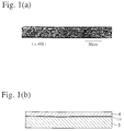
- Fig. 1 (a) is a photomicrograph at a magnification of 400
- Fig. 1 (b) is a schematic view of the photomicrograph of Fig. 1 (a).
- the laminated metal ribbon 9 had a cross-section structure having an extremely uniform third metal layer (vapor deposition layer) 11 sandwiched by the first and second metal ribbons 4, 5. It was confirmed by X-ray analysis that a diffusion layer of Ni constituting the third metal layer (vapor deposition layer) 11 and Cu constituting the first and second metal ribbons 4, 5 was formed in boundary regions between the vapor deposition layer 11 and the first and second metal ribbons 4, 5.
- a sample of 10 mm in width cut out of the laminated metal ribbon 9 was subjected to a peeling test that the first and second metal ribbons 4 and 5 were peeled from each other at a speed of 50 mm/minute, to measure a maximum load for peeling.
- the welding strength was 0.1 N/mm in the case of no heat treatment and 0.5 N/mm or more in the case of a heat treatment at 300°C, proving that the heat treatment for thermal diffusion sewed to increase the welding strength of the laminated metal ribbon 9.
- a stainless steel foil of 60 ⁇ m in thickness as a first metal ribbon 4 and a Ni foil of 10 ⁇ m in thickness as a second metal ribbon 5 were taken from winding reels 2, 3, respectively, and conveyed to a position where their welding surfaces were opposing a dry film-forming material of Ni disposed in a dry film-forming means 6 in a vacuum chamber 1 having a vacuum atmosphere of about 1 x 10 -2 Pa.
- Ni was deposited on the welding surfaces of the first and second metal ribbons 4, 5 by a dry film-forming (vacuum vapor deposition) method.
- the vapor-deposited surfaces of the first and second metal ribbons 4, 5 were pressure-welded by the rolls 8, 8 to produce a laminated metal ribbon 9 consisting of stainless steel foil / Ni vapor deposition layer / stainless steel foil.
- the resultant laminated metal ribbon 9 for safety valves of batteries was wound around a winding reel 10.
- the stainless steel foil of the laminated metal ribbon 9 was selectively etched to form circular holes of 3 mm in diameter in a lattice pattern having a pitch of 10.5 mm.
- the laminated metal ribbon 9 was then cut by a punch press to obtain 10 laminated metal pieces each 10.5 mm x 7.5 mm having one circular hole at a center for safety valve chips of batteries.
- Each safety valve chip was welded to a high-pressure steel-made container such that it sealed a valve opening of the high-pressure container. With a compressor connected to one end of the container via a pressure gauge, the container was pressurized. As a result, Ni foils in 10 safety valve chips were broken at a pressure of 1.3-1.7 MPa.
- the present invention has made it possible to produce, by a single step in the same vacuum chamber, a laminated metal ribbon having three or more layers that has conventionally been produced by two steps. Also, the present invention has made it easy to carry out ion-etching that is a pre-treatment of dry film-forming (vapor deposition). Thus, the laminated metal ribbon of the present invention can be produced at an extremely improved productivity.
Landscapes
- Chemical & Material Sciences (AREA)
- Engineering & Computer Science (AREA)
- Mechanical Engineering (AREA)
- Chemical Kinetics & Catalysis (AREA)
- Materials Engineering (AREA)
- Metallurgy (AREA)
- Organic Chemistry (AREA)
- Physics & Mathematics (AREA)
- Thermal Sciences (AREA)
- Physical Vapour Deposition (AREA)
- Pressure Welding/Diffusion-Bonding (AREA)
- Laminated Bodies (AREA)
Abstract
Description
Claims (10)
- A method for producing a laminated ribbon comprising the steps of (a) forming a film layer on at least one welding surface of a first ribbon and a second ribbon by a dry film-forming method in a vacuum chamber, the dry-formed film layer being made of the same material as or a different material from those of the first and second metal ribbons; and (b) pressure-welding the first ribbon to the second ribbon.
- A method for producing a laminated metal ribbon comprising the steps of (a) forming a third metal layer on at least one welding surface of a first metal ribbon and a second metal ribbon by a dry film-forming method in a vacuum chamber, said third metal being the same as or different from a metal or an alloy of said first and second metal ribbons; and (b) pressure-welding said first metal ribbon to said second metal ribbon.
- A method for producing a laminated metal ribbon comprising the steps of (a) forming a third metal layer on at least one welding surface of a first metal ribbon and a second metal ribbon by a dry film-forming method in a vacuum chamber, said third metal being the same as or different from a metal or an alloy of said first and second metal ribbons; (b) pressure-welding said first metal ribbon to said second metal ribbon; and (c) subjecting the resultant laminate to a heat treatment for thermal diffusion.
- The method for producing a laminated metal ribbon according to any one of claims 1-3, wherein said dry film-forming method is a physical vapor deposition method.
- A laminated ribbon having a dry-formed film layer between a first ribbon and a second ribbon.
- A laminated metal ribbon having a dry-formed film layer between a first metal ribbon and a second metal ribbon.
- The laminated metal ribbon according to claim 6, wherein a diffusion layer is formed in a boundary region between said dry-formed film layer and said first metal ribbon and/or between said dry-formed film layer and said second metal ribbon.
- An apparatus for producing a laminated ribbon by pressure-welding ribbons in a vacuum chamber, said vacuum chamber comprising (1) a plurality of winding reels for said ribbons; (2) a dry-film-forming means for forming a dry-formed film layer on at least one welding surface of said ribbons taken from said winding reels; (3) rolls for pressure-welding said ribbons with their welding surfaces facing each other; and (4) a winding reel for winding the resultant pressure-welded laminate ribbon.
- The apparatus for producing a laminated ribbon according to claim 8, wherein guide rolls are disposed at a position opposing said dry-film-forming means.
- The apparatus for producing a laminated ribbon according to claim 8 or 9, further comprising a heating means for carrying out a heat treatment for thermal diffusion of the pressure-welded laminate ribbon.
Applications Claiming Priority (2)
| Application Number | Priority Date | Filing Date | Title |
|---|---|---|---|
| JP26861099 | 1999-09-22 | ||
| JP26861099 | 1999-09-22 |
Publications (2)
| Publication Number | Publication Date |
|---|---|
| EP1086776A1 true EP1086776A1 (en) | 2001-03-28 |
| EP1086776B1 EP1086776B1 (en) | 2006-05-17 |
Family
ID=17460942
Family Applications (1)
| Application Number | Title | Priority Date | Filing Date |
|---|---|---|---|
| EP00120571A Expired - Lifetime EP1086776B1 (en) | 1999-09-22 | 2000-09-20 | Laminated ribbon and method and apparatus for producing same |
Country Status (4)
| Country | Link |
|---|---|
| US (1) | US6455172B1 (en) |
| EP (1) | EP1086776B1 (en) |
| DE (1) | DE60027976T2 (en) |
| TW (1) | TW466149B (en) |
Cited By (2)
| Publication number | Priority date | Publication date | Assignee | Title |
|---|---|---|---|---|
| EP1342564A4 (en) * | 2000-10-18 | 2010-03-03 | Toyo Kohan Co Ltd | Multilayered metal laminate and process for producing the same |
| GB2531097A (en) * | 2014-05-31 | 2016-04-13 | Gm Global Tech Operations Llc | Method for treating plate |
Families Citing this family (6)
| Publication number | Priority date | Publication date | Assignee | Title |
|---|---|---|---|---|
| US7297209B2 (en) * | 2003-12-18 | 2007-11-20 | Nitto Denko Corporation | Method and device for transferring anisotropic crystal film from donor to receptor, and the donor |
| KR100773391B1 (en) * | 2005-09-01 | 2007-11-05 | 한국전기연구원 | Lamination apparatus and lamination method using the same |
| DE102010062823A1 (en) * | 2010-12-10 | 2012-06-21 | Tesa Se | Adhesive composition and method for encapsulating an electronic device |
| CN102139407B (en) * | 2011-03-14 | 2013-04-17 | 谢振华 | Trace metal compounding process |
| JP6570146B2 (en) | 2014-10-09 | 2019-09-04 | マテリオン コーポレイション | Metal laminate having metallurgical bond and density-reduced metal core layer and method for producing the same |
| JP2021146359A (en) * | 2020-03-18 | 2021-09-27 | 三菱マテリアル株式会社 | Joined body and method for manufacturing joined body |
Citations (4)
| Publication number | Priority date | Publication date | Assignee | Title |
|---|---|---|---|---|
| US4011982A (en) * | 1975-09-15 | 1977-03-15 | Airco, Inc. | Surface joining by bonding of metal and deposited metal |
| JPS6027481A (en) * | 1983-07-22 | 1985-02-12 | Hitachi Ltd | Low pressure diffusion bonding method |
| JPH0491872A (en) * | 1990-08-07 | 1992-03-25 | Nisshin Steel Co Ltd | Manufacture of aluminum clad steel plate excellent in workability |
| US5895723A (en) * | 1993-08-26 | 1999-04-20 | Fraunhofer-Gesellschaft Zur Foerderung Der Angewandten Forschung E.V. | Composite films |
Family Cites Families (4)
| Publication number | Priority date | Publication date | Assignee | Title |
|---|---|---|---|---|
| JPH01133689A (en) | 1987-08-07 | 1989-05-25 | Fuji Denpa Koki Kk | Manufacture of clad material |
| JPH0755384B2 (en) | 1988-03-02 | 1995-06-14 | 東洋鋼板株式会社 | Clad metal plate manufacturing method and apparatus |
| JPH0755384A (en) | 1993-08-19 | 1995-03-03 | Sanden Corp | Multi-tube heat exchanger |
| JPH07214344A (en) | 1994-01-28 | 1995-08-15 | Hitachi Ltd | Laminating equipment |
-
2000
- 2000-09-20 EP EP00120571A patent/EP1086776B1/en not_active Expired - Lifetime
- 2000-09-20 DE DE60027976T patent/DE60027976T2/en not_active Expired - Lifetime
- 2000-09-22 US US09/667,724 patent/US6455172B1/en not_active Expired - Fee Related
- 2000-09-22 TW TW089119631A patent/TW466149B/en not_active IP Right Cessation
Patent Citations (4)
| Publication number | Priority date | Publication date | Assignee | Title |
|---|---|---|---|---|
| US4011982A (en) * | 1975-09-15 | 1977-03-15 | Airco, Inc. | Surface joining by bonding of metal and deposited metal |
| JPS6027481A (en) * | 1983-07-22 | 1985-02-12 | Hitachi Ltd | Low pressure diffusion bonding method |
| JPH0491872A (en) * | 1990-08-07 | 1992-03-25 | Nisshin Steel Co Ltd | Manufacture of aluminum clad steel plate excellent in workability |
| US5895723A (en) * | 1993-08-26 | 1999-04-20 | Fraunhofer-Gesellschaft Zur Foerderung Der Angewandten Forschung E.V. | Composite films |
Non-Patent Citations (2)
| Title |
|---|
| PATENT ABSTRACTS OF JAPAN vol. 009, no. 152 (M - 391) 27 June 1985 (1985-06-27) * |
| PATENT ABSTRACTS OF JAPAN vol. 016, no. 321 (M - 1279) 14 July 1992 (1992-07-14) * |
Cited By (2)
| Publication number | Priority date | Publication date | Assignee | Title |
|---|---|---|---|---|
| EP1342564A4 (en) * | 2000-10-18 | 2010-03-03 | Toyo Kohan Co Ltd | Multilayered metal laminate and process for producing the same |
| GB2531097A (en) * | 2014-05-31 | 2016-04-13 | Gm Global Tech Operations Llc | Method for treating plate |
Also Published As
| Publication number | Publication date |
|---|---|
| TW466149B (en) | 2001-12-01 |
| EP1086776B1 (en) | 2006-05-17 |
| DE60027976D1 (en) | 2006-06-22 |
| US6455172B1 (en) | 2002-09-24 |
| DE60027976T2 (en) | 2007-06-06 |
Similar Documents
| Publication | Publication Date | Title |
|---|---|---|
| KR100537322B1 (en) | Multilayered metal laminate and process for producing the same | |
| JP5517196B2 (en) | Superconducting compound substrate and manufacturing method thereof | |
| KR20120038410A (en) | Metal laminated substrate for use as an oxide superconducting wire material, and manufacturing method therefor | |
| US6455172B1 (en) | Laminated ribbon and method and apparatus for producing same | |
| US4011982A (en) | Surface joining by bonding of metal and deposited metal | |
| US20170084434A1 (en) | Diffusion-bonded sputter target assembly and method of manufacturing | |
| JP3975439B2 (en) | Metal mask | |
| JP2004185890A (en) | Metal mask | |
| US11642870B2 (en) | Glass carrier attached copper foil and method for producing same | |
| US20070157450A1 (en) | Bonding method of metal surfaces | |
| JP3339632B2 (en) | Manufacturing method of laminated metal strip and laminated metal strip | |
| US3369288A (en) | Method of diffusion bonding a honeycomb structure | |
| KR102890171B1 (en) | Sputtering target and manufacturing method thereof | |
| US20240026525A1 (en) | Sputtering Target and Method for Producing Sputtering Target | |
| JPH05230643A (en) | Stress control method for physical vapor deposition thin film | |
| JP2002120075A (en) | Method of manufacturing laminated metal foil for capacitor safety valve, laminated metal foil for capacitor safety valve, capacitor case lid and capacitor using laminated metal foil for capacitor safety valve | |
| KR102218282B1 (en) | Method manufacturing stacked structure for printed circuit board comprising ternary-compound and device operating thereof | |
| JP2002103058A (en) | Method of manufacturing laminated metal foil for battery safety valve, laminated metal foil for battery safety valve, battery case lid using the laminated metal foil for battery safety valve, and battery | |
| JPS6192431A (en) | Manufacture of magnetic recording medium | |
| JP2000246462A (en) | Manufacturing method of laminated metal sheet | |
| JP2002110748A (en) | Method for manufacturing laminated band for TAB and laminated band for TAB | |
| JP2002110880A (en) | Manufacturing method of laminated strip for lead frame | |
| JP2002067260A (en) | Manufacturing method of laminated strip and laminated strip | |
| JPS58202908A (en) | Manufacture of metallic thin plate | |
| JP2002224740A (en) | Method for producing metal foil and metal foil |
Legal Events
| Date | Code | Title | Description |
|---|---|---|---|
| PUAI | Public reference made under article 153(3) epc to a published international application that has entered the european phase |
Free format text: ORIGINAL CODE: 0009012 |
|
| AK | Designated contracting states |
Kind code of ref document: A1 Designated state(s): DE DK FR NL SE |
|
| AX | Request for extension of the european patent |
Free format text: AL;LT;LV;MK;RO;SI |
|
| 17P | Request for examination filed |
Effective date: 20010921 |
|
| AKX | Designation fees paid |
Free format text: DE DK FR NL SE |
|
| 17Q | First examination report despatched |
Effective date: 20050401 |
|
| GRAP | Despatch of communication of intention to grant a patent |
Free format text: ORIGINAL CODE: EPIDOSNIGR1 |
|
| GRAS | Grant fee paid |
Free format text: ORIGINAL CODE: EPIDOSNIGR3 |
|
| GRAA | (expected) grant |
Free format text: ORIGINAL CODE: 0009210 |
|
| AK | Designated contracting states |
Kind code of ref document: B1 Designated state(s): DE DK FR NL SE |
|
| PG25 | Lapsed in a contracting state [announced via postgrant information from national office to epo] |
Ref country code: NL Free format text: LAPSE BECAUSE OF FAILURE TO SUBMIT A TRANSLATION OF THE DESCRIPTION OR TO PAY THE FEE WITHIN THE PRESCRIBED TIME-LIMIT Effective date: 20060517 |
|
| REF | Corresponds to: |
Ref document number: 60027976 Country of ref document: DE Date of ref document: 20060622 Kind code of ref document: P |
|
| PG25 | Lapsed in a contracting state [announced via postgrant information from national office to epo] |
Ref country code: SE Free format text: LAPSE BECAUSE OF FAILURE TO SUBMIT A TRANSLATION OF THE DESCRIPTION OR TO PAY THE FEE WITHIN THE PRESCRIBED TIME-LIMIT Effective date: 20060817 Ref country code: DK Free format text: LAPSE BECAUSE OF FAILURE TO SUBMIT A TRANSLATION OF THE DESCRIPTION OR TO PAY THE FEE WITHIN THE PRESCRIBED TIME-LIMIT Effective date: 20060817 |
|
| NLV1 | Nl: lapsed or annulled due to failure to fulfill the requirements of art. 29p and 29m of the patents act | ||
| ET | Fr: translation filed | ||
| PLBE | No opposition filed within time limit |
Free format text: ORIGINAL CODE: 0009261 |
|
| STAA | Information on the status of an ep patent application or granted ep patent |
Free format text: STATUS: NO OPPOSITION FILED WITHIN TIME LIMIT |
|
| 26N | No opposition filed |
Effective date: 20070220 |
|
| PGFP | Annual fee paid to national office [announced via postgrant information from national office to epo] |
Ref country code: DE Payment date: 20090917 Year of fee payment: 10 |
|
| PGFP | Annual fee paid to national office [announced via postgrant information from national office to epo] |
Ref country code: FR Payment date: 20091012 Year of fee payment: 10 |
|
| REG | Reference to a national code |
Ref country code: FR Ref legal event code: ST Effective date: 20110531 |
|
| REG | Reference to a national code |
Ref country code: DE Ref legal event code: R119 Ref document number: 60027976 Country of ref document: DE Effective date: 20110401 |
|
| PG25 | Lapsed in a contracting state [announced via postgrant information from national office to epo] |
Ref country code: FR Free format text: LAPSE BECAUSE OF NON-PAYMENT OF DUE FEES Effective date: 20100930 Ref country code: DE Free format text: LAPSE BECAUSE OF NON-PAYMENT OF DUE FEES Effective date: 20110401 |