EP1086350B1 - A flow conduit and means for enlarging the surface thereof to provide cooling, and a fuel pipe, and a method for the manufacture thereof - Google Patents
A flow conduit and means for enlarging the surface thereof to provide cooling, and a fuel pipe, and a method for the manufacture thereof Download PDFInfo
- Publication number
- EP1086350B1 EP1086350B1 EP99957193A EP99957193A EP1086350B1 EP 1086350 B1 EP1086350 B1 EP 1086350B1 EP 99957193 A EP99957193 A EP 99957193A EP 99957193 A EP99957193 A EP 99957193A EP 1086350 B1 EP1086350 B1 EP 1086350B1
- Authority
- EP
- European Patent Office
- Prior art keywords
- cooling
- tubular element
- fuel
- blades
- cooling blades
- Prior art date
- Legal status (The legal status is an assumption and is not a legal conclusion. Google has not performed a legal analysis and makes no representation as to the accuracy of the status listed.)
- Expired - Lifetime
Links
- 238000001816 cooling Methods 0.000 title claims description 77
- 239000000446 fuel Substances 0.000 title claims description 55
- 238000004519 manufacturing process Methods 0.000 title claims description 4
- 238000000034 method Methods 0.000 title claims 3
- XAGFODPZIPBFFR-UHFFFAOYSA-N aluminium Chemical compound [Al] XAGFODPZIPBFFR-UHFFFAOYSA-N 0.000 claims description 5
- 229910052782 aluminium Inorganic materials 0.000 claims description 5
- 239000004411 aluminium Substances 0.000 claims description 3
- 239000002828 fuel tank Substances 0.000 claims description 2
- 239000007788 liquid Substances 0.000 claims description 2
- 238000005452 bending Methods 0.000 claims 3
- 230000008878 coupling Effects 0.000 claims 1
- 238000010168 coupling process Methods 0.000 claims 1
- 238000005859 coupling reaction Methods 0.000 claims 1
- 230000000694 effects Effects 0.000 description 5
- 238000009434 installation Methods 0.000 description 5
- 238000009835 boiling Methods 0.000 description 2
- 238000004140 cleaning Methods 0.000 description 2
- 239000000463 material Substances 0.000 description 2
- 239000004033 plastic Substances 0.000 description 2
- 229920003023 plastic Polymers 0.000 description 2
- 238000005086 pumping Methods 0.000 description 2
- 238000009825 accumulation Methods 0.000 description 1
- 239000002283 diesel fuel Substances 0.000 description 1
- 238000005516 engineering process Methods 0.000 description 1
- 238000001125 extrusion Methods 0.000 description 1
- 238000005461 lubrication Methods 0.000 description 1
- 239000000126 substance Substances 0.000 description 1
- 239000013589 supplement Substances 0.000 description 1
Images

Classifications
-
- F—MECHANICAL ENGINEERING; LIGHTING; HEATING; WEAPONS; BLASTING
- F28—HEAT EXCHANGE IN GENERAL
- F28F—DETAILS OF HEAT-EXCHANGE AND HEAT-TRANSFER APPARATUS, OF GENERAL APPLICATION
- F28F1/00—Tubular elements; Assemblies of tubular elements
- F28F1/10—Tubular elements and assemblies thereof with means for increasing heat-transfer area, e.g. with fins, with projections, with recesses
- F28F1/42—Tubular elements and assemblies thereof with means for increasing heat-transfer area, e.g. with fins, with projections, with recesses the means being both outside and inside the tubular element
-
- F—MECHANICAL ENGINEERING; LIGHTING; HEATING; WEAPONS; BLASTING
- F28—HEAT EXCHANGE IN GENERAL
- F28D—HEAT-EXCHANGE APPARATUS, NOT PROVIDED FOR IN ANOTHER SUBCLASS, IN WHICH THE HEAT-EXCHANGE MEDIA DO NOT COME INTO DIRECT CONTACT
- F28D1/00—Heat-exchange apparatus having stationary conduit assemblies for one heat-exchange medium only, the media being in contact with different sides of the conduit wall, in which the other heat-exchange medium is a large body of fluid, e.g. domestic or motor car radiators
- F28D1/02—Heat-exchange apparatus having stationary conduit assemblies for one heat-exchange medium only, the media being in contact with different sides of the conduit wall, in which the other heat-exchange medium is a large body of fluid, e.g. domestic or motor car radiators with heat-exchange conduits immersed in the body of fluid
- F28D1/04—Heat-exchange apparatus having stationary conduit assemblies for one heat-exchange medium only, the media being in contact with different sides of the conduit wall, in which the other heat-exchange medium is a large body of fluid, e.g. domestic or motor car radiators with heat-exchange conduits immersed in the body of fluid with tubular conduits
-
- F—MECHANICAL ENGINEERING; LIGHTING; HEATING; WEAPONS; BLASTING
- F02—COMBUSTION ENGINES; HOT-GAS OR COMBUSTION-PRODUCT ENGINE PLANTS
- F02M—SUPPLYING COMBUSTION ENGINES IN GENERAL WITH COMBUSTIBLE MIXTURES OR CONSTITUENTS THEREOF
- F02M31/00—Apparatus for thermally treating combustion-air, fuel, or fuel-air mixture
- F02M31/20—Apparatus for thermally treating combustion-air, fuel, or fuel-air mixture for cooling
-
- F—MECHANICAL ENGINEERING; LIGHTING; HEATING; WEAPONS; BLASTING
- F16—ENGINEERING ELEMENTS AND UNITS; GENERAL MEASURES FOR PRODUCING AND MAINTAINING EFFECTIVE FUNCTIONING OF MACHINES OR INSTALLATIONS; THERMAL INSULATION IN GENERAL
- F16L—PIPES; JOINTS OR FITTINGS FOR PIPES; SUPPORTS FOR PIPES, CABLES OR PROTECTIVE TUBING; MEANS FOR THERMAL INSULATION IN GENERAL
- F16L11/00—Hoses, i.e. flexible pipes
- F16L11/04—Hoses, i.e. flexible pipes made of rubber or flexible plastics
- F16L11/12—Hoses, i.e. flexible pipes made of rubber or flexible plastics with arrangements for particular purposes, e.g. specially profiled, with protecting layer, heated, electrically conducting
- F16L11/121—Hoses, i.e. flexible pipes made of rubber or flexible plastics with arrangements for particular purposes, e.g. specially profiled, with protecting layer, heated, electrically conducting specially profiled cross sections
-
- F—MECHANICAL ENGINEERING; LIGHTING; HEATING; WEAPONS; BLASTING
- F28—HEAT EXCHANGE IN GENERAL
- F28F—DETAILS OF HEAT-EXCHANGE AND HEAT-TRANSFER APPARATUS, OF GENERAL APPLICATION
- F28F1/00—Tubular elements; Assemblies of tubular elements
- F28F1/10—Tubular elements and assemblies thereof with means for increasing heat-transfer area, e.g. with fins, with projections, with recesses
- F28F1/12—Tubular elements and assemblies thereof with means for increasing heat-transfer area, e.g. with fins, with projections, with recesses the means being only outside the tubular element
-
- F—MECHANICAL ENGINEERING; LIGHTING; HEATING; WEAPONS; BLASTING
- F28—HEAT EXCHANGE IN GENERAL
- F28F—DETAILS OF HEAT-EXCHANGE AND HEAT-TRANSFER APPARATUS, OF GENERAL APPLICATION
- F28F1/00—Tubular elements; Assemblies of tubular elements
- F28F1/10—Tubular elements and assemblies thereof with means for increasing heat-transfer area, e.g. with fins, with projections, with recesses
- F28F1/40—Tubular elements and assemblies thereof with means for increasing heat-transfer area, e.g. with fins, with projections, with recesses the means being only inside the tubular element
-
- Y—GENERAL TAGGING OF NEW TECHNOLOGICAL DEVELOPMENTS; GENERAL TAGGING OF CROSS-SECTIONAL TECHNOLOGIES SPANNING OVER SEVERAL SECTIONS OF THE IPC; TECHNICAL SUBJECTS COVERED BY FORMER USPC CROSS-REFERENCE ART COLLECTIONS [XRACs] AND DIGESTS
- Y02—TECHNOLOGIES OR APPLICATIONS FOR MITIGATION OR ADAPTATION AGAINST CLIMATE CHANGE
- Y02T—CLIMATE CHANGE MITIGATION TECHNOLOGIES RELATED TO TRANSPORTATION
- Y02T10/00—Road transport of goods or passengers
- Y02T10/10—Internal combustion engine [ICE] based vehicles
- Y02T10/12—Improving ICE efficiencies
Definitions
- the present invention relates to a flow conduit comprising a tubular element for conveying a liquid therein, said tubular element having an outer surface, an upper portion of said outer surface having a planar or a convex shape; cooling blades connected to and extending outward from said outer surface of said tubular element, each of said cooling blades having a base section and an outer section.
- the fuel system in a vehicle serves to supply fuel to the motor from the tank installation of that vehicle.
- the fuel is pumped into an advance conduit leading to the motor.
- the fuel which is not consumed in the motor is extremely hot and is pumped back into the tank via a return conduit.
- WO 94/23257 discloses a heat exchanger that has among its objects to cool fuel in the fuel system of a vehicle, wherein the cooler has been inserted between two conduits in the return conduit.
- this cooler is very space-intensive, and in that cooler a very large loss of pressure occurs in the return conduit which means that a large pumping capacity is required to return the amount of fuel in the return conduit to the tank.
- EP-0 807 756 teaches a fuel system for a vehicle wherein a tubular section is inserted that has axially oriented cooling ribs for cooling the fuel in the advance and return conduits in the fuel system. At each of its ends, this tubular section is connected by means of tubes to the motor and tank installations, respectively.
- the tubular section comprises two parallel flow conduits and is provided with cooling ribs that allow the fuel to be cooled in a simple manner by the streams of air underneath the bottom of the vehicle.
- EP-0 807 756 eliminates the drawbacks in connection with pressure drops and large pumping capacity, and usual tubing underneath the bottom is also utilised which saves space compared to previously.
- dirt may accumulate on this cooling profile that may deposit on top of and between the cooling ribs and thus reduce the cooling effect or even have an insulating effect on the profile tubing.
- this known type of fuel pipe comprises mechanical joints, eg soldered joints between eg fuel tubing, connector tubing and cooler tubing. Such joints present a risk of leak. This risk is greatly increased when the fuel is to be advanced in the fuel pipe under pressure. It is therefore desirable to be able to manufacture a fuel system with a minimum of joints, especially welded joints and soldered joints, in order to hereby reduce the risk of leaks occurring due to a weak joint.
- the invention consists of a flow conduit of the kind described above wherein each of said cooling blades is bent downwards at said base section with respect to said tubular element; and in that each tubular element further comprises cooling fins on said outer section of each of said cooling blades, wherein each of said cooling fins is connected to one of said cooling blades at a point of attachment and has a downwardly inclined cooling surface with respect to said point of attachment.
- the flow conduit according to the invention is in one embodiment an extruded aluminum profile.
- Aluminum is extremely heat-conductive and easily deformable which means that the profile according to this embodiment is uncomplicated to manufacture by extrusion and, the material thus chosen also yields an adequate cooling effect.
- the flow conduit it is made with internal cooling fins. Hereby a further cooling of the flow medium in the conduit is obtained.
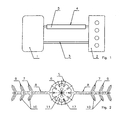
- Figure 1 shows the fuel system between a tank 1 and a motor 2.
- the fuel flows from the tank 1 and onwards to the motor 2. Excessive fuel is conveyed back to the tank 1 via a return flow 4.
- a part of the fuel is used for lubrication of eg pumps in the motor 2, and therefore the amount of fuel conveyed to the motor 2 exceeds the amount combusted.
- the fuel can thus be circulated in an amount of about thrice the tank volume.
- the fuel is heated by passage through the motor installation 2, and accordingly it is necessary to cool the fuel in the return conduit 4.
- the return flow 4 is therefore provided with a fuel pipe according to the invention for cooling the fuel flowing therethrough to ensure that the fuel will neither, due to too elevated temperature, destroy the tank nor, due to chemical reacation with material in connection with the tank, will the combustibility of the fuel be reduced, eg by boiling, but is kept cooled to a harmless suitably low temperature.
- This fuel pipe is configured in a cooling profile 5 as shown in the cross sectional views of Figures 2 through 4.
- FIG. 2 illustrates the preferred embodiment of a profile 5 for cooling fuel in accordance with the invention.
- the profile 5 is an extruded aluminium profile that exhibits a centrally arranged tubular element 6 in which a flow conduit 11 is configured.
- the profile 5 is configured with two cooling blades 7 that extend diametrically from the tubular element 6.
- Each cooling blade 7 exhibits a bendable base section 8 and an outer section 9 that comprises a number of cooling fins 10.
- the flow conduit 11 in the tubular element 6 is provided with internal cooling ribs 17 whereby the cooling effect of the aluminium profile can be further increased.
- the cooling blades 7 can be bent in the base section 8 whereby the cooling fins 10 in the outer section 9 feature downwardly inclined surfaces 12. Hereby dirt will slide off the cooling fins 10 that thus continue to have a cooling effect.
- Angulation of the cooling blades 7 means that the cooling profile 5 according to the invention will appear as compact and it will retain a high cooling surface. It being also substantially self-cleaning, the profile 5 according to the invention is suitable for use as a fuel pipe.
- Figure 4 shows how the profile 5 can be mounted underneath the bottom 13 of a vehicle.
- cooling fins 10 can alternatively or as supplement also be configured in the bendable section 8.
- FIG. 5 shows a fuel pipe 4 configured in a cooling profile 5 according to the invention.
- the pipe 4 is configured with a number of sections 14,15,16 wherein the cooling blades have been removed.
- the tubular element is thus essentially exposed whereby angulation of the tubular element is considerably facilitated, in particular in the light of the angulations often having different orientations since the configuration of the fuel pipe is a spatial shape.
- cooling blades 7 can be removed by cutting-off or the like in one or more sections 15 in order to create space for fittings (not shown) .
- the cooling blades 7 have also been removed which means that in the tubular portion 6 a connecting branch can be configured that matches the reception opening in tank and motor installations 1,2, respectively.
- the flow conduit is built by means of two units in that a cooling element with cooling fins and/or cooling ribs have been attached to surface portions of a tubular element.
- the cooling element is preferably attached to surface portions that face sideways or downwards, and the cooling fins extend outwards or downwards relative to the tubular portion.
- a flow conduit having this configuration is suitable for mounting underneath the bottom of a vehicle, since it is possible to arrange the cooling element(s) according to desire on those areas of the tube that are not bent and where there are no fittings or the like for securing the pipe.
- the cooling element can eg be soldered or attached by deformation to the pipe in order to hereby provide adequate heat conductivity between the tubular element and the cooling element.
Landscapes
- Engineering & Computer Science (AREA)
- General Engineering & Computer Science (AREA)
- Physics & Mathematics (AREA)
- Mechanical Engineering (AREA)
- Thermal Sciences (AREA)
- Geometry (AREA)
- Chemical & Material Sciences (AREA)
- Combustion & Propulsion (AREA)
- Cooling, Air Intake And Gas Exhaust, And Fuel Tank Arrangements In Propulsion Units (AREA)
- Heat-Exchange Devices With Radiators And Conduit Assemblies (AREA)
- Shaping By String And By Release Of Stress In Plastics And The Like (AREA)
Description
Claims (12)
- A flow conduit comprisinga tubular element (5) for conveying a liquid therein, said tubular element (5) having an outer surface, an upper portion of said outer surface having a planar or a convex shape;cooling blades (8) connected to and extending outward from said outer surface of said tubular element, each of said cooling blades (8) having a base section and an outer section, characterized in that each of said cooling blades (8) is bent downwards at said base section with respect to said tubular element (5); and in that each tubular element further comprisescooling fins (7, 9, 10) on said outer section of each of said cooling blades (8), wherein each of said cooling fins (7, 9, 10) is connected to one of said cooling blades (8) at a point of attachment and has a downwardly inclined cooling surface with respect to said point of attachment.
- The flow conduit of claim 1, wherein said cooling blades (8) comprise two cooling blades connected to said tubular element (5) at diametrically opposed sides of said outer surface.
- The flow conduit of claim 1, wherein said cooling surface of each of said cooling fins (7, 9, 10) is inclined away from said tubular element (5).
- The flow conduit of claim 1, wherein said tubular element (5), said cooling blades (8), and said cooling fins (7, 9, 10) are integrally connected and are formed of extruded aluminium.
- The flow conduit of claim 1, wherein said tubular element (5) has at least one flow passage formed therein, each of said at least one flow passage having cooling ribs (17) formed on an inner surface thereof.
- The flow conduit of claim 1, wherein said tubular element (5) and said cooling blades (8) are not integrally connected, each of said cooling blades (8) abutting against said outer surface of said tubular element (5).
- A vehicle fuel system comprising:a fuel tank;a vehicle motor anda tubular element (5) connecting to said tank and said motor for conveying fuel between said tank and said motor, wherein said tubular element is according to any one of the claims 1-6.
- The fuel system of claim 7, wherein at least one of the end portions of said tubular element (5) is free of any cooling blades (8) and includes a coupling member connecting said tubular element (5) to at least one of said motor and said tank.
- The fuel system of claim 7, wherein said tubular element (5) comprises a fuel return pipe for conveying fuel from said motor to said tank.
- A method of manufacturing the fuel system of claim 2, comprisingextruding said tubular element (5), said cooling blades, and said cooling fins as a single, integral unit; andbending said tubular element (5) at said at least one bend area so as to shape said tubular element to fit between said motor and said tank.
- The method of claim 10, further comprising :notching said cooling blades (8) to remove at least one section of said cooling blades (8) so as to form said at least one bend area.
- The method of claim 10, further comprising :bending each of said cooling blades (8) downwardly at said bending section such that each cooling surface of each of said cooling fins (7, 9, 10) is downwardly inclined with respect to said point of attachment.
Applications Claiming Priority (3)
| Application Number | Priority Date | Filing Date | Title |
|---|---|---|---|
| DK199800792A DK79298A (en) | 1998-06-08 | 1998-06-08 | Profile of fuel cooling, a fuel line and a process for making them |
| DK98792 | 1998-06-08 | ||
| PCT/DK1999/000300 WO1999067590A1 (en) | 1998-06-08 | 1999-06-07 | A flow conduit and means for enlarging the surface thereof to provide cooling, and a fuel pipe, and a method for the manufacture thereof |
Publications (2)
| Publication Number | Publication Date |
|---|---|
| EP1086350A1 EP1086350A1 (en) | 2001-03-28 |
| EP1086350B1 true EP1086350B1 (en) | 2003-04-02 |
Family
ID=8097618
Family Applications (1)
| Application Number | Title | Priority Date | Filing Date |
|---|---|---|---|
| EP99957193A Expired - Lifetime EP1086350B1 (en) | 1998-06-08 | 1999-06-07 | A flow conduit and means for enlarging the surface thereof to provide cooling, and a fuel pipe, and a method for the manufacture thereof |
Country Status (9)
| Country | Link |
|---|---|
| US (1) | US6321792B1 (en) |
| EP (1) | EP1086350B1 (en) |
| JP (1) | JP2002519615A (en) |
| KR (1) | KR20010052646A (en) |
| AU (1) | AU4256399A (en) |
| DE (1) | DE69906522T2 (en) |
| DK (1) | DK79298A (en) |
| ES (1) | ES2196881T3 (en) |
| WO (1) | WO1999067590A1 (en) |
Families Citing this family (10)
| Publication number | Priority date | Publication date | Assignee | Title |
|---|---|---|---|---|
| DE19916530A1 (en) * | 1999-04-13 | 2000-10-19 | Mannesmann Vdo Ag | Device for supplying an internal combustion engine of a motor vehicle with fuel |
| US7242850B2 (en) | 2001-02-23 | 2007-07-10 | Eastman Kodak Company | Frame-interpolated variable-rate motion imaging system |
| DE102004049670B4 (en) * | 2004-10-12 | 2008-12-11 | Veritas Ag | Fuel cooler, motor vehicle with such a fuel cooler |
| US9100124B2 (en) | 2007-05-24 | 2015-08-04 | Federal Law Enforcement Development Services, Inc. | LED Light Fixture |
| US20090114300A1 (en) * | 2007-11-02 | 2009-05-07 | Shyuan-Han Shyu | Fire hose with outer indication textures and inner flow guide textures |
| US20110226782A1 (en) * | 2010-03-17 | 2011-09-22 | Gm Global Technology Operations, Inc. | Gas temperature moderation within compressed gas vessel through heat exchanger |
| US20150345708A1 (en) * | 2013-01-08 | 2015-12-03 | Agility Fuel Systems, Inc. | Vortex fill |
| DE102013020469A1 (en) * | 2013-12-06 | 2015-06-11 | Webasto SE | Heat exchanger and method for producing a heat exchanger |
| US11391523B2 (en) * | 2018-03-23 | 2022-07-19 | Raytheon Technologies Corporation | Asymmetric application of cooling features for a cast plate heat exchanger |
| CN112629023A (en) * | 2020-12-24 | 2021-04-09 | 浙江创能新能源股份有限公司 | Heat pump water heater |
Family Cites Families (20)
| Publication number | Priority date | Publication date | Assignee | Title |
|---|---|---|---|---|
| DE363398C (en) | 1922-11-09 | Hans Lipke | Electric cigar lighter | |
| US2322341A (en) * | 1940-01-27 | 1943-06-22 | Morris F Booth | Heat exchange unit |
| US2405722A (en) * | 1943-02-27 | 1946-08-13 | Charles J Villier | Heat exchange structure |
| US2566318A (en) * | 1949-03-21 | 1951-09-04 | Svenska Maskinverken Ab | Method of making an extended surface heat exchange device or similar composite article |
| US3145456A (en) * | 1956-06-21 | 1964-08-25 | Olin Mathieson | Method of manufacturing finned structure |
| FR1479486A (en) | 1966-03-14 | 1967-05-05 | Special profile tube for the constitution of heat exchangers | |
| US3735465A (en) * | 1969-01-21 | 1973-05-29 | Airco Inc | Assembling apparatus for rolling and clamping a part to a tubular member |
| GB1551366A (en) * | 1975-04-30 | 1979-08-30 | Leeuwen E Van | Solar heat exchange device |
| DE2627967A1 (en) | 1975-07-09 | 1977-01-27 | Anton Schwarz | Finned radiator section with central tube - has radial heat dissipating fins, ribs or corrugations inside tube |
| JPS54101539A (en) * | 1978-01-27 | 1979-08-10 | Kobe Steel Ltd | Heat exchange pipe for use with water-sprinkling type, panel-shaped, liquefied natural gas evaporator and combination of such pipes and their manufacturing method |
| US4241727A (en) * | 1978-11-06 | 1980-12-30 | Toti Andrew J | Structural assembly, method of forming same, and elongated panel structure resulting therefrom |
| AU534683B2 (en) * | 1979-10-23 | 1984-02-09 | Ahearn Main & Stott Pty. Ltd. | Strip for forming a solar collector |
| EP0038710A1 (en) | 1980-04-23 | 1981-10-28 | Barry William Wilder | Petrol cooling arrangement for engines |
| CH647592A5 (en) * | 1980-07-10 | 1985-01-31 | Cryomec Ag | HEAT TRANSFER ELEMENT, ESPECIALLY FOR CREATING A HEAT EXCHANGER FOR CRYOGENEOUS APPLICATIONS. |
| FR2491202B1 (en) | 1980-10-01 | 1986-02-28 | Air Liquide | ATMOSPHERIC HEATER |
| US5174371A (en) * | 1992-01-27 | 1992-12-29 | Cryoquip, Inc. | Atmospheric vaporizer heat exchanger |
| US5467818A (en) * | 1993-03-24 | 1995-11-21 | Valeo Climate Control Corporation | Heat exchanger |
| NZ263135A (en) | 1993-03-29 | 1996-05-28 | Melanesia Int Trust | Heat exchanger: finned hollow body with passages for heat exchange medium; end manifolds |
| DE19617718A1 (en) * | 1996-04-24 | 1997-10-30 | Uwe Klix | Ceiling radiator |
| DE19619934A1 (en) | 1996-05-17 | 1997-11-20 | Bayerische Motoren Werke Ag | Fuel line system |
-
1998
- 1998-06-08 DK DK199800792A patent/DK79298A/en not_active Application Discontinuation
-
1999
- 1999-06-07 JP JP2000556204A patent/JP2002519615A/en not_active Withdrawn
- 1999-06-07 WO PCT/DK1999/000300 patent/WO1999067590A1/en not_active Ceased
- 1999-06-07 KR KR1020007013879A patent/KR20010052646A/en not_active Ceased
- 1999-06-07 EP EP99957193A patent/EP1086350B1/en not_active Expired - Lifetime
- 1999-06-07 US US09/719,100 patent/US6321792B1/en not_active Expired - Fee Related
- 1999-06-07 ES ES99957193T patent/ES2196881T3/en not_active Expired - Lifetime
- 1999-06-07 DE DE69906522T patent/DE69906522T2/en not_active Expired - Fee Related
- 1999-06-07 AU AU42563/99A patent/AU4256399A/en not_active Abandoned
Also Published As
| Publication number | Publication date |
|---|---|
| US6321792B1 (en) | 2001-11-27 |
| DK79298A (en) | 1999-12-09 |
| DE69906522D1 (en) | 2003-05-08 |
| DE69906522T2 (en) | 2004-02-12 |
| AU4256399A (en) | 2000-01-10 |
| WO1999067590A1 (en) | 1999-12-29 |
| EP1086350A1 (en) | 2001-03-28 |
| ES2196881T3 (en) | 2003-12-16 |
| JP2002519615A (en) | 2002-07-02 |
| KR20010052646A (en) | 2001-06-25 |
Similar Documents
| Publication | Publication Date | Title |
|---|---|---|
| US6321792B1 (en) | Flow conduit and means for enlarging the surface thereof to provide cooling, and a fuel pipe, and a method for the manufacture thereof | |
| EP0602968B1 (en) | Oil coolers for motor vehicles | |
| US6032726A (en) | Low-cost liquid heat transfer plate and method of manufacturing therefor | |
| US20030080036A1 (en) | Fluid filter with integrated cooler | |
| US7694724B2 (en) | Engine cooling radiator | |
| US4167969A (en) | Transmission cooler | |
| US6129142A (en) | Radiator thermal expansion joint and method for making the same | |
| EP1995423A2 (en) | Fan shroud structure | |
| CN122015530A (en) | Sealing systems and methods for cooling fluids in sealing assemblies | |
| EP0724129A1 (en) | Heat exchanger tank for assembly in a heat exchanger and method of producing it | |
| US7740457B2 (en) | Means for delivery of flowable media, especially lubricants | |
| CN101910772A (en) | device for cooling the coolant | |
| EP1130222B1 (en) | Oil cooler for internal combustion engines | |
| US20090145592A1 (en) | Windshield washer fluid heating system | |
| US2054403A (en) | Oil cooling system | |
| US8033321B2 (en) | Heat exchanger and method of manufacturing | |
| EP0632246A2 (en) | Heat exchanger | |
| US6953080B2 (en) | Front end structure of vehicle preventing short-circuit of cooling air | |
| EP0889299A3 (en) | Heat exchanger having a double pipe construction | |
| US5881803A (en) | Heat exchanger construction | |
| CN214701886U (en) | Heat radiator | |
| US8840380B2 (en) | Temperature control ring for vehicle air pump | |
| KR200195015Y1 (en) | Cooling apparatus for oil | |
| KR100662243B1 (en) | Automotive Oil Cooler | |
| KR100839175B1 (en) | Radiator side support coupling structure |
Legal Events
| Date | Code | Title | Description |
|---|---|---|---|
| PUAI | Public reference made under article 153(3) epc to a published international application that has entered the european phase |
Free format text: ORIGINAL CODE: 0009012 |
|
| 17P | Request for examination filed |
Effective date: 20001114 |
|
| AK | Designated contracting states |
Kind code of ref document: A1 Designated state(s): DE ES FR GB IT SE |
|
| 17Q | First examination report despatched |
Effective date: 20010814 |
|
| GRAH | Despatch of communication of intention to grant a patent |
Free format text: ORIGINAL CODE: EPIDOS IGRA |
|
| GRAH | Despatch of communication of intention to grant a patent |
Free format text: ORIGINAL CODE: EPIDOS IGRA |
|
| GRAA | (expected) grant |
Free format text: ORIGINAL CODE: 0009210 |
|
| AK | Designated contracting states |
Designated state(s): DE ES FR GB IT SE |
|
| REG | Reference to a national code |
Ref country code: GB Ref legal event code: FG4D |
|
| REF | Corresponds to: |
Ref document number: 69906522 Country of ref document: DE Date of ref document: 20030508 Kind code of ref document: P |
|
| PG25 | Lapsed in a contracting state [announced via postgrant information from national office to epo] |
Ref country code: SE Free format text: LAPSE BECAUSE OF FAILURE TO SUBMIT A TRANSLATION OF THE DESCRIPTION OR TO PAY THE FEE WITHIN THE PRESCRIBED TIME-LIMIT Effective date: 20030702 |
|
| REG | Reference to a national code |
Ref country code: ES Ref legal event code: FG2A Ref document number: 2196881 Country of ref document: ES Kind code of ref document: T3 |
|
| ET | Fr: translation filed | ||
| PLBE | No opposition filed within time limit |
Free format text: ORIGINAL CODE: 0009261 |
|
| STAA | Information on the status of an ep patent application or granted ep patent |
Free format text: STATUS: NO OPPOSITION FILED WITHIN TIME LIMIT |
|
| 26N | No opposition filed |
Effective date: 20040105 |
|
| PGFP | Annual fee paid to national office [announced via postgrant information from national office to epo] |
Ref country code: GB Payment date: 20040602 Year of fee payment: 6 |
|
| PGFP | Annual fee paid to national office [announced via postgrant information from national office to epo] |
Ref country code: FR Payment date: 20040608 Year of fee payment: 6 |
|
| PGFP | Annual fee paid to national office [announced via postgrant information from national office to epo] |
Ref country code: DE Payment date: 20040617 Year of fee payment: 6 |
|
| PGFP | Annual fee paid to national office [announced via postgrant information from national office to epo] |
Ref country code: ES Payment date: 20040621 Year of fee payment: 6 |
|
| PG25 | Lapsed in a contracting state [announced via postgrant information from national office to epo] |
Ref country code: IT Free format text: LAPSE BECAUSE OF NON-PAYMENT OF DUE FEES;WARNING: LAPSES OF ITALIAN PATENTS WITH EFFECTIVE DATE BEFORE 2007 MAY HAVE OCCURRED AT ANY TIME BEFORE 2007. THE CORRECT EFFECTIVE DATE MAY BE DIFFERENT FROM THE ONE RECORDED. Effective date: 20050607 Ref country code: GB Free format text: LAPSE BECAUSE OF NON-PAYMENT OF DUE FEES Effective date: 20050607 |
|
| PG25 | Lapsed in a contracting state [announced via postgrant information from national office to epo] |
Ref country code: ES Free format text: LAPSE BECAUSE OF NON-PAYMENT OF DUE FEES Effective date: 20050608 |
|
| PG25 | Lapsed in a contracting state [announced via postgrant information from national office to epo] |
Ref country code: DE Free format text: LAPSE BECAUSE OF NON-PAYMENT OF DUE FEES Effective date: 20060103 |
|
| PG25 | Lapsed in a contracting state [announced via postgrant information from national office to epo] |
Ref country code: FR Free format text: LAPSE BECAUSE OF NON-PAYMENT OF DUE FEES Effective date: 20060228 |
|
| GBPC | Gb: european patent ceased through non-payment of renewal fee |
Effective date: 20050607 |
|
| REG | Reference to a national code |
Ref country code: FR Ref legal event code: ST Effective date: 20060228 |
|
| REG | Reference to a national code |
Ref country code: ES Ref legal event code: FD2A Effective date: 20050608 |