EP1085742A2 - Automatic document feeder - Google Patents
Automatic document feeder Download PDFInfo
- Publication number
- EP1085742A2 EP1085742A2 EP00307684A EP00307684A EP1085742A2 EP 1085742 A2 EP1085742 A2 EP 1085742A2 EP 00307684 A EP00307684 A EP 00307684A EP 00307684 A EP00307684 A EP 00307684A EP 1085742 A2 EP1085742 A2 EP 1085742A2
- Authority
- EP
- European Patent Office
- Prior art keywords
- document
- chassis
- paper
- adf
- sheet
- Prior art date
- Legal status (The legal status is an assumption and is not a legal conclusion. Google has not performed a legal analysis and makes no representation as to the accuracy of the status listed.)
- Granted
Links
Images


Classifications
-
- G—PHYSICS
- G03—PHOTOGRAPHY; CINEMATOGRAPHY; ANALOGOUS TECHNIQUES USING WAVES OTHER THAN OPTICAL WAVES; ELECTROGRAPHY; HOLOGRAPHY
- G03G—ELECTROGRAPHY; ELECTROPHOTOGRAPHY; MAGNETOGRAPHY
- G03G15/00—Apparatus for electrographic processes using a charge pattern
- G03G15/60—Apparatus which relate to the handling of originals
-
- B—PERFORMING OPERATIONS; TRANSPORTING
- B41—PRINTING; LINING MACHINES; TYPEWRITERS; STAMPS
- B41J—TYPEWRITERS; SELECTIVE PRINTING MECHANISMS, i.e. MECHANISMS PRINTING OTHERWISE THAN FROM A FORME; CORRECTION OF TYPOGRAPHICAL ERRORS
- B41J13/00—Devices or arrangements of selective printing mechanisms, e.g. ink-jet printers or thermal printers, specially adapted for supporting or handling copy material in short lengths, e.g. sheets
- B41J13/10—Sheet holders, retainers, movable guides, or stationary guides
- B41J13/103—Sheet holders, retainers, movable guides, or stationary guides for the sheet feeding section
-
- B—PERFORMING OPERATIONS; TRANSPORTING
- B65—CONVEYING; PACKING; STORING; HANDLING THIN OR FILAMENTARY MATERIAL
- B65H—HANDLING THIN OR FILAMENTARY MATERIAL, e.g. SHEETS, WEBS, CABLES
- B65H1/00—Supports or magazines for piles from which articles are to be separated
- B65H1/02—Supports or magazines for piles from which articles are to be separated adapted to support articles on edge
- B65H1/025—Supports or magazines for piles from which articles are to be separated adapted to support articles on edge with controlled positively-acting mechanical devices for advancing the pile to present the articles to the separating device
-
- B—PERFORMING OPERATIONS; TRANSPORTING
- B65—CONVEYING; PACKING; STORING; HANDLING THIN OR FILAMENTARY MATERIAL
- B65H—HANDLING THIN OR FILAMENTARY MATERIAL, e.g. SHEETS, WEBS, CABLES
- B65H29/00—Delivering or advancing articles from machines; Advancing articles to or into piles
- B65H29/16—Delivering or advancing articles from machines; Advancing articles to or into piles by contact of one face only with moving tapes, bands, or chains
- B65H29/18—Delivering or advancing articles from machines; Advancing articles to or into piles by contact of one face only with moving tapes, bands, or chains and introducing into a pile
-
- B—PERFORMING OPERATIONS; TRANSPORTING
- B65—CONVEYING; PACKING; STORING; HANDLING THIN OR FILAMENTARY MATERIAL
- B65H—HANDLING THIN OR FILAMENTARY MATERIAL, e.g. SHEETS, WEBS, CABLES
- B65H3/00—Separating articles from piles
- B65H3/02—Separating articles from piles using friction forces between articles and separator
- B65H3/06—Rollers or like rotary separators
- B65H3/0669—Driving devices therefor
-
- B—PERFORMING OPERATIONS; TRANSPORTING
- B65—CONVEYING; PACKING; STORING; HANDLING THIN OR FILAMENTARY MATERIAL
- B65H—HANDLING THIN OR FILAMENTARY MATERIAL, e.g. SHEETS, WEBS, CABLES
- B65H31/00—Pile receivers
- B65H31/02—Pile receivers with stationary end support against which pile accumulates
-
- H—ELECTRICITY
- H04—ELECTRIC COMMUNICATION TECHNIQUE
- H04N—PICTORIAL COMMUNICATION, e.g. TELEVISION
- H04N1/00—Scanning, transmission or reproduction of documents or the like, e.g. facsimile transmission; Details thereof
- H04N1/00567—Handling of original or reproduction media, e.g. cutting, separating, stacking
- H04N1/0057—Conveying sheets before or after scanning
- H04N1/00588—Conveying sheets before or after scanning to the scanning position
-
- H—ELECTRICITY
- H04—ELECTRIC COMMUNICATION TECHNIQUE
- H04N—PICTORIAL COMMUNICATION, e.g. TELEVISION
- H04N1/00—Scanning, transmission or reproduction of documents or the like, e.g. facsimile transmission; Details thereof
- H04N1/00567—Handling of original or reproduction media, e.g. cutting, separating, stacking
- H04N1/0057—Conveying sheets before or after scanning
- H04N1/00591—Conveying sheets before or after scanning from the scanning position
- H04N1/00594—Conveying sheets before or after scanning from the scanning position along at least a part of the same path as transport to the scanning position
-
- H—ELECTRICITY
- H04—ELECTRIC COMMUNICATION TECHNIQUE
- H04N—PICTORIAL COMMUNICATION, e.g. TELEVISION
- H04N1/00—Scanning, transmission or reproduction of documents or the like, e.g. facsimile transmission; Details thereof
- H04N1/00567—Handling of original or reproduction media, e.g. cutting, separating, stacking
- H04N1/0057—Conveying sheets before or after scanning
- H04N1/00599—Using specific components
- H04N1/00602—Feed rollers
-
- H—ELECTRICITY
- H04—ELECTRIC COMMUNICATION TECHNIQUE
- H04N—PICTORIAL COMMUNICATION, e.g. TELEVISION
- H04N1/00—Scanning, transmission or reproduction of documents or the like, e.g. facsimile transmission; Details thereof
- H04N1/00567—Handling of original or reproduction media, e.g. cutting, separating, stacking
- H04N1/0062—Removing sheets from a stack or inputting media
-
- H—ELECTRICITY
- H04—ELECTRIC COMMUNICATION TECHNIQUE
- H04N—PICTORIAL COMMUNICATION, e.g. TELEVISION
- H04N1/00—Scanning, transmission or reproduction of documents or the like, e.g. facsimile transmission; Details thereof
- H04N1/00681—Detecting the presence, position or size of a sheet or correcting its position before scanning
- H04N1/00684—Object of the detection
- H04N1/00708—Size or dimensions
- H04N1/0071—Width
-
- H—ELECTRICITY
- H04—ELECTRIC COMMUNICATION TECHNIQUE
- H04N—PICTORIAL COMMUNICATION, e.g. TELEVISION
- H04N1/00—Scanning, transmission or reproduction of documents or the like, e.g. facsimile transmission; Details thereof
- H04N1/00681—Detecting the presence, position or size of a sheet or correcting its position before scanning
- H04N1/00684—Object of the detection
- H04N1/00708—Size or dimensions
- H04N1/00713—Length
-
- H—ELECTRICITY
- H04—ELECTRIC COMMUNICATION TECHNIQUE
- H04N—PICTORIAL COMMUNICATION, e.g. TELEVISION
- H04N1/00—Scanning, transmission or reproduction of documents or the like, e.g. facsimile transmission; Details thereof
- H04N1/00795—Reading arrangements
-
- B—PERFORMING OPERATIONS; TRANSPORTING
- B65—CONVEYING; PACKING; STORING; HANDLING THIN OR FILAMENTARY MATERIAL
- B65H—HANDLING THIN OR FILAMENTARY MATERIAL, e.g. SHEETS, WEBS, CABLES
- B65H2301/00—Handling processes for sheets or webs
- B65H2301/30—Orientation, displacement, position of the handled material
- B65H2301/34—Modifying, selecting, changing direction of displacement
-
- B—PERFORMING OPERATIONS; TRANSPORTING
- B65—CONVEYING; PACKING; STORING; HANDLING THIN OR FILAMENTARY MATERIAL
- B65H—HANDLING THIN OR FILAMENTARY MATERIAL, e.g. SHEETS, WEBS, CABLES
- B65H2301/00—Handling processes for sheets or webs
- B65H2301/40—Type of handling process
- B65H2301/42—Piling, depiling, handling piles
- B65H2301/421—Forming a pile
- B65H2301/4214—Forming a pile of articles on edge
- B65H2301/42142—Forming a pile of articles on edge by introducing articles from beneath
-
- B—PERFORMING OPERATIONS; TRANSPORTING
- B65—CONVEYING; PACKING; STORING; HANDLING THIN OR FILAMENTARY MATERIAL
- B65H—HANDLING THIN OR FILAMENTARY MATERIAL, e.g. SHEETS, WEBS, CABLES
- B65H2405/00—Parts for holding the handled material
- B65H2405/30—Other features of supports for sheets
- B65H2405/33—Compartmented support
- B65H2405/331—Juxtaposed compartments
- B65H2405/3312—Juxtaposed compartments for storing articles vertically or inclined (>45)
- B65H2405/33125—Feed tray juxtaposed to discharge tray
-
- G—PHYSICS
- G03—PHOTOGRAPHY; CINEMATOGRAPHY; ANALOGOUS TECHNIQUES USING WAVES OTHER THAN OPTICAL WAVES; ELECTROGRAPHY; HOLOGRAPHY
- G03G—ELECTROGRAPHY; ELECTROPHOTOGRAPHY; MAGNETOGRAPHY
- G03G2215/00—Apparatus for electrophotographic processes
- G03G2215/00172—Apparatus for electrophotographic processes relative to the original handling
- G03G2215/00206—Original medium
- G03G2215/00316—Electronic image supplied to the apparatus
-
- H—ELECTRICITY
- H04—ELECTRIC COMMUNICATION TECHNIQUE
- H04N—PICTORIAL COMMUNICATION, e.g. TELEVISION
- H04N2201/00—Indexing scheme relating to scanning, transmission or reproduction of documents or the like, and to details thereof
- H04N2201/04—Scanning arrangements
- H04N2201/0402—Arrangements not specific to a particular one of the scanning methods covered by groups H04N1/04 - H04N1/207
- H04N2201/0422—Media holders, covers, supports, backgrounds; Arrangements to facilitate placing of the medium
Definitions
- the present invention relates generally to an automatic document feeder for use with a scanning device.
- a copying apparatus when working with cut sheet print media, a copying apparatus often includes an automatic document feeder (“ADF”) mechanism for automatically loading and unloading single sheet sequentially to a functional station where the copying apparatus performs an operation - e.g., sequentially scans the fed document sheets for copying, faxing, displaying on a computer monitor, or the like. Following the operation, the ADF then off-loads that sheet and feeds the immediately following sheet of the document to the functional station.
- a sequential flow of sheets by the ADF and positioning without the necessity of manual handling reduces the time required to accomplish the complete functional operation.
- Media which already contains printed matter hereinafter referred to generically as a "document" presents a need for precise alignment to a scanning station in order to generate a true copy.
- Typical commercial ADFs generally require a document sheet pre-picking mechanism to ensure a single sheet gets to a pick roller, especially in systems having a horizontal input paper tray.
- Most commercial ADFs for scanners scroll the document page-by-page passed a stationary scan head and into an output tray.
- This makes pre-scanning and other multiple scanning operations difficult or even impossible, leading to degraded scan output quality.
- Belt type document feeders which place a document onto a flat, transparent, scanning bed, have also been developed.
- One such system is shown in commonly assigned U.S. Patent No. 5,342,133 (Canfield).
- a beltless drive system is disclosed in commonly assigned U.S. Patent No. 5,788,227 (Hendrix).
- Paper jam Two major problems associated with business machines that include an ADF are the occasional mis-feed (or "paper jam") and a multiple sheet feed. Paper jams interrupt operation and require manual correction of the problem before the automated conveying can be restarted. Multiple sheet feed can result in a missing page in the copy.
- a third common problem is the inadvertent skewing of the document page in the loading and unloading of paper sheets on the glass of a scanner or copier. Skewing can often lead to a paper jam.
- a first conventional method is to affix a paper drive mechanism axle to the ADF structure and turn the axle with a motor and gear train or timing belt linkage. The motor and the linkage are also rigidly mounted to the ADF structure.
- the disadvantage of this method is that it is difficult to balance the normal force between the two drive rollers.
- the stiff elastomer durometer acts as a spring constant and any minor difference in the roller diameter, roller run-out, or roller position relative to the bed will result in a significant difference in the normal force between the two rollers.
- a second conventional method is to spring load an axle to the ADF structure, turning the end of the axle with a motor and gear train or timing belt linkage.
- the motor is rigidly mounted to the ADF structure.
- the linkage moves with the axle and pivots about the motor shaft.
- the disadvantage is that it becomes substantially impossible to balance the normal force between the two drive rollers.
- the linkage generates unequal force when moving the drive roller axle in a forward direction versus a reverse direction. Because the linkage is positioned at the end of the axle, this unequal force teeters the drive roller axle and results in uneven normal forces.
- a third conventional method is to again spring load the axle to the ADF structure, again turning the end of the axle with a motor and gear train or timing belt linkage with the motor and image moving with the axle.
- a fourth conventional method is to spring load an axle to the ADF structure and turn the axle in the middle. Both the motor and linkage move with the axle.
- the disadvantages of this method are that the motor weight far exceeds the required drive roller normal force and therefore requires a complicated suspension system in the middle of the ADF structure where it is geometrically constrained and that the motor suspension is susceptible to transportation shocks.
- the present invention seeks to provide an improved document feeder.
- an automatic document feeder as specified in claim 1.
- the preferred embodiment can provide an inexpensive ADF, having a simple paper path and being adaptable for hard copy apparatus that employ a flat bed document scanners.
- a modular ADF for use with a flat bed input device such as a flat bed scanner or flat bed copier, includes a modular chassis including a main chassis disposed between an upper chassis and a lower chassis for defining a complete paper path onto and off of the flat bed scanner.
- a modular chassis including a main chassis disposed between an upper chassis and a lower chassis for defining a complete paper path onto and off of the flat bed scanner.
- the modular construction facilitates assembly of a chassis that defines a complete paper path onto and off of a flatbed scanner in a fast and efficient manner.
- Another advantage is that it permits simple plastic injection molding manufacture of the chassis constructs.
- Still another advantage is that the use of a minimal number of foundational ADF units minimizes the tolerance accumulations among features as well as manufacturing assembly time and skill requirements. Accordingly, this embodiment can achieve manufacturing cost reduction while providing a reliable ADF.
- the modular ADF includes an attachment hinge mechanism that advantageously provides precision alignment of the ADF to the scanner without the use of tools.
- the preferred embodiment also includes a quick connect-disconnect of the ADF to a base unit and a low profile, small footprint, document output tray.
- the preferred embodiment is configured such that it allows lifting of the ADF and direct access to the base unit copying surface to permit band copying such as for brochures and books.
- the preferred embodiment is also configured such that it eliminates the need for a pre-picking mechanism to ensure paper gets to a pick roller provides a paper drive mechanism having balanced drive roller normal forces to ensure loading and unloading paper sheets without skew.
- the ADF may be provided with a background plate that includes a plate member and a plurality of support members extending downwardly from the plate member.
- the support members support the plate member in spaced relation to a scanner so that a document can be fed therebetween for scanning.
- the space between the plate member and scanner is sufficient to allow passage of the document, the space is small enough to prevent shadowing effects.
- the plate member need not be raised when a document is fed onto the scanner, lowered prior to scanning and then raised again so that the document can be removed, as is the case with other background plates.
- ADFs incorporating the present background plate need not include a lift mechanism for the plate, thereby reducing component, assembly and repair costs.
- an automatic document feeder 101 which is constructed in accordance with the preferred embodiment and which is adapted for use with a flat bed scanner 1101.
- the automatic document feeder 101 will be referred to hereinafter as "the ADF" for simplicity purposes.
- flat bed scanner 1101 Although in the preferred embodiment of the present invention reference is made to a flat bed scanner 1101, those skilled in the art will understand any type of flat bed input device can be utilized, such as a flat bed copier.
- the ADF 101 is modular in nature and generally comprises a set of assemblies or chassis including a main chassis 401 (FIGS. 4-5), an upper chassis 601 (FIGS. 6A-7), and a lower chassis 801 (FIGS. 8A-8D).
- the three chassis 401, 601, and 801 when assembled together form a medium path (P) that extends from a medium input tray 403 best seen in FIG. 11, to a medium output tray 803 as illustrated in FIG. 8C.
- P medium path
- FIGS. 10 and 11 illustrates the assembled ADF 101 with the top case 1001 in place relative to a generic scanner 1101.
- the three chassis 401, 601, and 801 are each unitary, injection molded plastic parts adapted for simple assembly.
- Commercial embodiment drawings are provided herein; therefore, it will be recognized by those skilled in the art that many features shown in the drawings are related to the molding process rather than to operational features. Injection molding process features are known to be design expedient and implementation specific; therefore, no further explanation is required in order to understand the invention as claimed.
- the construct presents to the end-user a simple input document slot 1013, backed by an input tray 403, where the stacked document sheets are loaded laterally, print side down, i.e., rearwardly facing. Note that the document is loaded in a "landscape" orientation regardless of the print orientation on the individual sheets.
- the only other feature of the assembled ADF construct apparent to the end-user is an output tray 803, protruding upwardly behind the input tray 403, where collated output document pages are received from the internal paper transport mechanism following scanning or copying, for example.
- Output sheets are received within a gap between the input tray 403 backside and the output tray 803 front side, best seen in FIGS. 2 and 3.
- Any control panel features which may be provided in a specific implementation, e.g., START and STOP pushbuttons, can also be provided in an accessible location on the top case 1001.
- This modular construction establishes the complete input-to-output paper path.
- the main chassis 401 is a unitary injection molded plastic part.
- the main chassis 401 is provided with all the features to house the operationally functional features of the ADF 101, namely motors, gear trains, shafts, paper picks and rollers, document lift assembly, and electronic controller equipment, and to establish an input paper path.
- Some functional features of the main chassis 401 are related to the interfit of the three chassis and paper drive mechanism and, therefore, further explanation of these features is relevant.
- the main chassis 401 includes an integrally formed main chassis shell 405 having a substantially planar base 407.
- An input tray 403 rises upwardly and rearwardly from the base 407.
- the input tray 403 has a document receiving surface 409 that has a concave shape, in both vertical and horizontal planes. This double-concave shape assists in both properly aligning the sheets of a multi-sheet input document (not shown) and stiffening the document to facilitate sheet feeding without jamming. See also , U.S. Pat. Appl. Ser. No. 08/706,032, filed by Hong on Aug.
- a sliding paper length adjuster, or simply "slider,” 1005 can be mounted to the input tray 403.
- the main chassis shell 405 includes three cavity areas 413, 417, and 419 respectively that are functionally related.
- the cavity area 413 is a central cavity that is disposed between the cavity areas 417 and 419, which are hereinafter called a left side main chassis cavity 417, and a right side main chassis cavity 419.
- the construct of the shell 405 includes a group of upper right side interfit features 415 and a group of left side interfit features 416.
- the right group of interfit features 415 is disposed on the right side of the main chassis central cavity area 413
- the left group of interfit features 416 is disposed on the left side of the main chassis central cavity area 413.
- the configuration of the groups of interfit features 415 and 416 facilitates the construct of the main chassis 401 in a fast and efficient manner.
- the upper chassis 601 mates between the interfit features 415 and 416 permitting the upper chassis 601 to easily drop into the central cavity area 413 of the main chassis 401.
- the rear side of the main chassis 401 is also configured to matingly engage the lower chassis 801.
- the lower chassis 801 is easily mounted on the rear side of the main chassis 401 by a set of four screws such as screw 1010.
- a set of molded screw retainer bushings such as a bushing 50, are provided to align where the lower chassis 801 is screw mounted to the main chassis 401.
- a sheet feed gap is created between the input tray surface 409 and a rear portion of the upper chassis 601 at about the central cavity area 413.
- Document sheets loaded into the input tray 403 drop sequentially in seriatim through this gap to travel onto the supporting surface of the flat bed input device 1101 as will be explained hereinafter in greater detail.
- a sheet receiving gap is created between the lower chassis 801 and the lower rear of the main chassis 401.
- the cavity area 417 is sufficiently large in volume to receive therein a left side stepper motor 103.
- the stepper motor 103 is mounted within the cavity area 413 by and suitable mounting devices, such as the mounting devices 1010.
- the cavity area 417 is open outwardly from the central cavity area 413 in order to facilitate ease of assembling the step motor 103 within the cavity 417.
- the right side cavity area 419 also has a sufficiently large volume to receive therein a right side stepper motor 301, that is substantially similar in construction to the left side stepper motor 103.
- the right side stepper motor 301 like the left side stepper motor 103 is mounted within the cavity area 419 by conventional mounting devices 1010.
- stepper motors 103 and 301 are coupled to the respective stepper motors 103 and 301 in a conventional manner which is well known to those skilled in the art. It is sufficient to note however, that the stepper motors 103 and 301 are sequenced in operation by a controller 1003.
- the controller 1003, as best seen in FIG 10B is configured in the form of a printed circuit board having electrical cabling indicated generally at 1007 that interconnects electrically the controller 1003 with the motors 103 and 301 as well as other electrical components in the ADF 101.
- the printed circuit board is dimensioned to be received within a front cavity area 421 of the main chassis 401.
- a main cross beam 603 is positioned to traverse the main chassis first cavity 413 parallel to the input tray 403 (FIGS. 1-3 and 10).
- a left side cantilever 607 and a right side cantilever 608 extend forwardly from each end of the cross beam 603.
- Each cantilever 607, 608 is provided with interfit features along the lower and side edges thereof, or as otherwise necessary for a particular implementation, which mate with the main chassis interfit features 416, 415, respectively.
- the upper chassis 601 is a unitary injection molded plastic piece part; molding features and interfit features will be specific to a particular design implementation.
- the upper chassis 601 is also secured to the main chassis 401 with conventional fasteners 1010 as shown in FIGS. 10A-10B.
- the rear of the cross beam 603 is provided with a plurality of protruding fins 605.
- the fins 605 are in close proximity to the input tray surface 409 as seen in FIG. 3.
- the document sheets are held between the input tray surface 409 and the upper chassis fins 605.
- Molded leaf spring features 609, 610 are provided to retain a transfer shaft 2003 (FIG. 20) using bushings 625, 626 as shown in FIG. 16.
- a separator shaft 628 (FIG. 9A) is mounted to the upper chassis 601 using molded capture bearings and a bushing (not shown) and another molded leaf spring 622 (FIG. 7) provided to retain a bushing (not shown).
- the separator shaft 628 bears a fixedly mounted central paper separator wheel 631 (FIG. 9A).
- One end of the separator shaft 628 is coupled to a motor (not shown in this FIG.) via gearing 633 (FIG. 2) and is driven during a paper feed cycle.
- a spring retainer 611 holds a compression spring (not shown). As shown in FIG. 10A, a tray sensor 701 and a pick sensor 703 as would be known in the art.
- the lower chassis 801 is shown in further detail in FIGS. 8A - 8L, along with a quick release attachment hinge 821.
- the entire lower chassis 801 is a unitary injection molded plastic part.
- a document output tray 803 has a surface 805 that provides a shallow concave curvature in a short height form factor -- in the dimensional region of half the paper width, e.g., approximately one-half that of an A-size to legal size paper sheet equal to about 4.25 inches. Again this takes advantage of paper stiffness induced when it is shaped into a semi-cylindrical form along its longitudinal axis.
- this embodiment can have a lower height form factor that no longer needs to support a remaining half of a document sheet by requiring such well known prior art mechanisms as output tray pull-out extensions, wire frame clips, or the like.
- an upper chassis left stanchion 807 and an upper chassis right stanchion 808 are integrally molded parts of the lower chassis 801, protruding forwardly from the output tray surface 805.
- the two stanchions 807, 808 are used for mounting the lower chassis 801 via appropriately molded interfit features to the main chassis 401 with fasteners 1010any suitable known or proprietary type.
- a document sheet output guide and shelf 809 extends forwardly.
- Output tray paper guide fins 811 protrude upwardly from the shelf 809 to lift the leading lateral edge of a sheet of output paper, directing it to follow along the output tray surface 805.
- the output tray 803, like the input tray 403, has a substantially vertical orientation.
- the gap between the two trays 403, 803 provides access for retrieval of the collated output document sheets.
- a paper depressor 813 is added to the central region of the surface 805 of the output tray 803.
- lower extremities 815 are formed to snap-fit to the paper pick and stop shaft 1203 (as shown in FIG. 15).
- the paper depressor 813 is made of a low friction material such as commercially available CycoloyTM, made by the General Electric company of One Plastics Avenue, Pittsfield, MA 01201. This design has been proven to work reliably for plain papers from 16-pound to 24-pound types at any acute angle less than forty-fives degrees to vertical as long as the output tray height is at least one-half the document sheet length.
- the paper sheets are forced into a cylindrical shape and stiffened. Without the depressor 813, the output tray angle to vertical should be reclining sufficiently to retain the paper sheets upright.
- the hinge 821 enables the modular chassis 401, 601, and 801 when assembled to be mounted to the flat bed scanner 1101 with a precisely aligned document feed path relative to the supporting surface of the scanner 1101.
- the hinge 821 facilitates at least two different ADF/scanner orientations for document scanning purposes coupled with a quick release feature for disconnecting the ADF 101 from the scanner 1101.
- the lower chassis 801 serves as a mount for the ADF hinge 821.
- FIG. 8A the lower chassis 801 serves as a mount for the ADF hinge 821.
- this attachment hinge 821 provides a dual purpose mechanism, both for mounting the assembled three chassis ADF 101 to either a compatible copier or scanner or to a bezel 1101 adapted to overlay such a copier or scanner flat bed scanning surface and for raising and lowering the ADF off a flat bed bezel without removal of the entire ADF system.
- a crossbeam 823 is provided with a set of hinge axle retainers 825, 826, 827, 828, 829, 830.
- Axle retainers 825, 828, and 830 are rearwardly facing and axle retainers 826, 827, and 829 are forwardly facing.
- the lower chassis 801 is provided with three axle casings 831, 832, and 833. Turning to FIG.
- three lower chassis attachment hinge axles 834 are provided to swivel mount the attachment hinge 821 to the lower chassis 801 in the shown manner via the axle retainers 825 - 830 and axle casings 831 - 833 with each of the axle casings riding an axle between a complementary pair of reversed-facing axle retainers, e.g., the casing element 831 is between retainer elements 825 and 826; see also FIGS. 8I - 8L.
- a pair of attachment hinge flanges 835 are mounted to the attachment hinge 821 by suitable fasteners 1010 and depend from the crossbeam 823. As shown in FIG. 11, in combination with the crossbeam 823, the flanges 835 are used to mount the assembled ADF to either a compatible copier or scanner 1101 or to a bezel adapted to overlay such a copier or scanner flat bed scanning surface.
- the flanges 835 are provided with dimensions sufficient not only to provide a steady, accurate aligning of the ADF, but also with a length sufficient to allow for lifting of the ADF vertically without removing the entire ADF from the scanner 1101 or flat bed, such as when the document pages to be scanned are in a book or magazine.
- the lower extremity of the hook 835 us provided with a flexible hook 837 adapted to catch a complementary lip or edge of the bezel or scanner flange receiving slots ( see e.g., FIG. 11, sleeve 1103).
- FIG. 8B shows that the bottom of the lower chassis output document sheet guide and shelf 809 is provided with depending ADF tilt-up stops 841.
- FIG. 8E shows that the crossbeam 823 of the attachment hinge 821 is provided with rising protrusions that form complementary, hinge tilt-up stops 842.
- the tilt-up stops 841, 842 in the preferred embodiment are matched such that a 65-degree rotation upward of the ADF is permitted ( see detail plane B -- B, FIG. 8B).
- FIGS. 8I - 8L depict the interfit of the hinge features with the lower chassis features.
- FIG. 11 shows the ADF 101 at its upwardly tilted position relative to the scanner 1101. Note that this also facilitates mounting the ADF to a scanner provided with appropriate flange slots or a scanner 1101 with receiving sleeves 1103.
- FIG. 12 shows an embodiment of input tray paper stop and pick mechanism 1201.
- FIG. 13 shows the paper stop mechanism 1201 mounted in position with respect to the input tray 403 with the mechanism in a paper loading, or "home,” position; the upper chassis is not shown in position in this drawing.
- FIG. 14 shows the paper stop and pick mechanism 1201 mounted in position with respect to input tray 403 with the paper stop and pick mechanism in a "retracted” position as it would be during a paper picking operation.
- the paper pick roller 1205 generally having a rubber or grit wheel surface, is mounted via a fixed bearing hub 1207.
- a pair of spaced apart spring loaded paper stop fence devices 1209 are mounted on opposite sides of the pick roller 1205.
- the stops 1209 protrude into the paper path (P) and support from below a stack of sheets of paper (not shown) loaded into the ADF 101.
- the stops 1209 temporarily rotate out of the paper path allowing the picked single sheet to fall under the force of gravity from the stack to start a journey along the paper path to the output tray 801 as will be explained in greater detail. Once the picked sheet has cleared the stops 1209, the stops 1209 snap back into the their original resting positions to support from below any remaining sheets in the stack.
- each paper stop fence device 1209 includes a housing 1211, a one-way needle clutch 1213, and a biasing torsional spring 1215, biasing the device toward its home position as depicted in FIG. 13.
- the housing 1211 has extended paper stop fence tabs 1217.
- the torsional spring 1215 provides enough force on the housing 1211 such that the tabs 1217 can support a number of sheets of a document (e.g., 50 sheets of legal size paper of up to 24-pound type).
- a paper pick drive shaft 1203 connects the paper stop and pick mechanism 1201 to a stepper motor 103.
- the mounting of the drive shaft 1203 to a motor 103 is made with standard bushings 1501.
- the force of a moving document sheet imparted by the pick roller 1205 is sufficient to release the clutch 1213 and push the tabs 1217 out of the way as shown in FIG. 14.
- the torsional spring 1215 causes the tabs 1217 to bounce back to the home position after the trailing edge of the paper clears the outermost point on the tabs.
- the present invention takes advantage of the vertical input tray 403 in that paper falls into the pick roller by gravity, eliminating the need for pre-picking mechanism.
- FIG. 16 shows an assembled paper drive2001 (detailed in FIG. 20) and a document backer 1601, referred to in the assembled combination as a paper pressure mechanism 1611.
- the ADF described herein uses the technique of sequentially loading and unloading original document sheets onto the scanner flat bed glass 1701 (FIGS. 17 - 19) using a document backing method taught in U.S. Patent Application Ser. No. 08/651,066 (Hendrix et al.), supra .
- a document backer 1601 includes a lift plate 1603 is a substantially rigid, planar material, such as a molded ABS plastic.
- a foam rubber pad 1605 preferably of polyurethane, commercially available from Boyd company of 13885 Ramona Avenue, Chino, California, providing a document backing pressure pad for a document sheet on the scanning bed glass 1701 at a scanning station.
- a thin plastic film 1607 preferably of polycarbonate film, trade name "Lexan”, commercially available from General Electric company of One Plastics Avenue, Pittsfield, MA 01201, is provided to act as a low-friction contact with document sheets.
- the combination of materials used in the document backer assembly 1601 and the lifting of the assembly during loading and unloading of print media sheets from the flat bed of a scanner, or bezel, not only reduces the friction, but also minimizes the electrostatic buildup, improving reliability of sheet feeding.
- the document backing assembly 1601 is mounted to the undercarriage of the main chassis 401 by slipping the assembly through the main chassis first cavity 413.
- the document backing assembly 1611 is inserted through the first cavity 413 of the main chassis 401; front hooks 1610, 1612 mate with molded features of the main chassis under carriage toward the front thereof; spring 1614 loaded bushings 1613 are provided to hold the document backing assembly 1601 in molded features of the main chassis toward the rear thereof, adjacent the first cavity 413 as shown in FIG. 10A.
- the embodiment solves the problem of getting a document sheet between the glass 1701 and the plastic film 1607 by lifting the assembled paper drive 2001 and document backer 1601 as the document sheet is loaded and unloaded from the glass.
- a lift cam mechanism 1609 moves between:
- the cam lift mechanism 1609 will be described hereinafter in greater detail.
- FIG. 20 shows detail of the paper drive mechanism 2001.
- the reversible stepper motor 301 is coupled to a transfer shall 2003 via a conventional gear train, or other transmission, 2005.
- a pair of paper drive rollers 2007, 2008 are mounted on a paper drive roller axle 2009.
- the paper drive roller axle 2009 has spring-loaded mountings 2011, 2012 to the ADF main chassis 401 structure as depicted in FIG. 15.
- a gear train linkage 2013 is used to turn the paper drive rollers 2007, 2008 via axle 2009 at the approximate midpoint of the axle.
- the gear train linkage 2013 moves with the axle and pivots about the transfer shaft 2003. Note that both the motor 301 and the transfer shaft 2003 is rigidly mounted to the ADF main chassis 401 structure.
- the normal force of the two drive rollers 2007, 2008 is balanced because the gear train linkage force is applied in the middle of the two drive rollers and therefore is equally distributed.
- the balanced normal force ensures loading and unloading of sheets of the document without skew.
- the spring loaded drive axle 2009 coupled to the system transmission system activates the elastomeric drive roller 2007 and 2008 to help facilitate the loading and unloading of a document sheet onto the supporting surface of the flat bed scanner 1101 without any substantial paper skew.
- the gear train linkage 2013 is used to provide motion to a lift cam during paper loading and unloading to hoist the document backer 1601 off the glass (FIGS. 17 and 19).
- FIGS. 9A-9G depict the dynamics of the paper path established by the main chassis 401, upper chassis 601 and lower chassis 801.
- a bezel 902 is attached to the apparatus 101.
- FIG. 9A shows the apparatus 101 in the condition where a document sheet 901 is loaded.
- the paper stop and pick mechanism 1201 is in the position shown in FIG. 13, and the document sheet 901 is resting on the two paper stop and pick mechanisms 1201 and paper pick roller 1205.
- the lift cam mechanism 1609 is in the same position as shown in FIG. 18, with the document backing assembly 1601 in its lowered position.
- FIG. 9B demonstrates pertinent apparatus feature positions during a paper pick operation.
- the paper pick roller 1205 is motor-activated, turning so as to pull the sheet 901 downward into the tray.
- the sheet 901 is fed downward and shaped between the input tray surface 409 and the upper chassis 601 fins 605.
- the tabs 1217 of the paper stop and pick mechanism 1201 are moved out of the way by the sheet 901 as described with respect to FIG. 12.
- the leading edge 903 of sheet 901 is directed toward the drive rollers 2007, 2008.
- Activation of the drive rollers 2007, 2008 turning in a rotation that will receive the leading edge 903 of sheet 901 and direct it toward the scanning station, also moves the cam mechanism 1609 to its forward position, lifting the document backing assembly 1601 such that the sheet will slip underneath.
- the leading edge 903 of the sheet 901 contacts the surface of the glass bed before reaching the drive rollers 2007, 2008. It has been found that the buckling of the sheet as it impacts the glass 1701 and before reaching the drive rollers 2007, 2008 de-skews any offset of the sheet.
- the drive rollers 2007, 2008 drive the sheet onto the glass 1701.
- the trailing edge of sheet 901 remains in contact with the drive rollers 2007, 2008 when the sheet is positioned for scanning.
- the lift cam mechanism 1609 returns to its center position and drops the document backing assembly 1601 onto the sheet 901.
- the drive rollers 2007,2008 are driven in a reverse direction from a sheet feed cycle.
- the lift cam mechanism 1609 is moved to its rearward position as shown in FIG. 19, lifting the document backing assembly 1601 to permit a sheet of paper 901 to be driven off the glass 1701.
- the trailing edge of the sheet 901 that had been retained under the drive roller 2007, 2008 has now become the exit "leading edge" 905 of the sheet.
- the lower chassis output document sheet guide and shelf 809 receives the exit leading edge 905.
- the sheet is driven between the output tray drive rollers 1503 (see also FIG. 15).
- the output tray drive rollers 1503 directs the sheet 901 upwardly into the output tray 803 where it is retained behind the shelf 809 as shown in FIG. 9G.
- the lift cam mechanism 1609 is returned to its center position.
- FIGS. 9A-G and 21-25 there is shown a lift cam mechanism 1609 that facilitates the lifting of an assembled paper drive 2001 and document backer 1601 during the loading and unloading of a document sheet onto the transparent glass supporting surface 1701.
- the lift cam mechanism 1609 solves the problem of transporting such a document sheet between the supporting surface 1701 and the plastic film 1607 during such loading and unloading operations.
- the lift cam mechanism 1609 generally includes a cam linkage indicated generally at 1615, and a differential gear train arrangement indicated generally at 1617.
- the cam linkage 1615 and the differential gear train arrangement 1617 in combination facilitate a passive automatic lifting action of the document backer 1601 to substantially reduce friction and electrostatic build up for reliable sheet feeding purposes.
- the cam linkage 1617 generally includes an elongated transfer shalt 2003 that is supported for rotational movement between a motor plate 1619 and the chassis 401.
- a pair of transfer gears, 8001 and 8002 respectively, are pressed mounted spaced from one another on the shaft 2003 to facilitate a lifting action enabled by a free spinning lift cam 8005 that will be described hereinafter in greater detail.
- the transfer gear 8001 has a larger diameter than the transfer gear 8002 and is mounted relative to the shaft 2003 so that it engages a motor pinion gear 1621 extending from the drive motor 103. In this manner, the motor pinion gear 1621 translates the rotational drive of the motor 103 to the transfer gear 8001 that in turn causes the shaft 2003 to be rotated about it axis at a desired rotational speed.
- the lift cam 8005 and a free spinning transfer idler gear 8003 are mounted inwardly of the transfer gear 8002 on the shaft 2003.
- the idler gear 8003 and the lift cam 8005 are slightly spaced from one another with the lift cam 8005 being mounted furthest from the distal end of the shaft 2003.
- An elongated lift cam pin 8006 is mounted fixedly by wedging to the lift cam 8005 and extends outwardly therefrom parallel to the shaft 2003.
- a free spinning drive roller 2007 is pressed mounted to a drive shaft 2009 having a press fitted drive gear 8008 mounted to its distal end.
- the drive shaft 2009 is mounted spaced from and parallel with the transfer shaft 2003 and is supported between the motor plate 1621 and a free spinning cluster housing 8010.
- the cluster housing 8010 mounted inwardly of the drive gear 8008 and is supported on and between the transfer shaft 2003 and the drive shaft 2009.
- the cluster housing 8010 has fixed thereto an elongated housing pin 8009 that extends outwardly therefrom in a plane parallel with the shafts 2003 and 2009.
- a free spinning cluster housing composite gear 8007 is mounted on the pin 8009 between shafts 2003 and 2009.
- the composite gear 8007 includes a large diameter portion that engages the drive gear 8008 and a small diameter portion that engages the transfer idler gear 8003 to further facilitate a lifting action as will be hereinafter described.
- the lift cam 8005 includes a pair of spaced apart stops 8005A and 8005B that limit the movement of the lift cam 8005 as will be explained hereinafter in greater detail.
- the lift cam 8005 begins in a down position as best seen in FIG. 21.
- the transfer gear 8001 imparts a counter clockwise rotation to the transfer shaft 2003.
- the transfer shaft 2003 causes the lift cam 8005 to lift and to move to a final lifted position as shown in FIG. 22.
- the gear 8002 rotates in the same counter clockwise direction and at the same rotational speed as that of the shaft 2003.
- the idler gear 8003 remains in a fixed position due to the friction between the drive roller 2007 and the scanner glass bed 1701.
- the idler gear 8003 locks the gear train of gears 8003, 8007 and 8008.
- the drive shaft 2009, its associated drive roller 2007 and cluster housing 8010 also remain fixed in their respective positions.
- the free spinning lift cam composite gear 800 rides along the transfer gear 8002 and the idler gear 8003, and rotates in response to cause the lift cam 8005 and lift cam pin 8006 to move in unison, pivoting in a clockwise direction relative to the transfer shaft 2003.
- the drive roller 2007 starts driving the document forward. More particularly, the drive roller 2007 imparts motion to the document in the following manner. Motion of the lift cam 8005 is inhibited by the stops 8005A and 8005B that are wedged on the lift plate 1603. With the lift cam in a fixed position, the lift cam composite gear 8004 continues to rotate on pin 8006 in a clockwise direction that now in turn, imparts a rotational motion to the gear train comprising gears 8003, 8007 and 8008. In this regard, the gear 8003 is rotated in a counter clockwise direction, which motion is coupled to the drive gear 8008 via the clockwise motion of gear 8007 about pin 8009.
- the lift cam 8005 is moved to its original down position as illustrated in FIG. 21.
- the transfer shaft 2003 starts to rotate in an opposite clockwise direction, that in turn, causes the transfer gear 8003 to rotate in the same clockwise direction.
- the lift cam composite gear 8004 riding along gears 8002 and 8003 rotates in an opposite direction causing the lift cam 8005 and its associated pin 8006 to pivot on the transfer shaft 2003.
- Motion of the drive roller 2007, drive shaft 2009 and the cluster housing 8010 remain fixed as no rotation motion is imparted via gears 8007 and 8008.
- the motor pinion gear rotates in a counter clockwise direction, it imparts a clockwise motion to the transfer shaft 2003 via the transfer gear 8001.
- the rotation of the transfer shaft 2003 causes the transfer gear 8002 to rotate in the same direction at the same rotational speed, while the idler gear 8003 remains in a stationary position. Again, the friction between the drive roller 2007 and the document locks the gear train comprising the gears 8008, 8007, and 8003. Thereafter, the lift cam 8005 remains in a fixed position while the document is scanned.
- the lift cam 8005 is lifted to permit the document to be moved off of the scanner glass bed 1701.
- the motor pinion gear is rotated in a counter clockwise direction that in turn imparts a clockwise rotation to the transfer shaft 2003 and the transfer gear 8002. That is shaft 2003 rotates via the engagement of the transfer gear 8001 with the motor pinion gear, and the gear 8002 rotates as it is fixed to the shaft 2003.
- the friction between the drive roller 2007 and the document locks the gear train of gears 8003, 8007 and 8008 in a fixed position.
- the lift cam 8005 then begins to lift.
- the composite gear 8004 free spins on pin 8006 and rides along gears 8002 and 8003 causing the lift cam 8005 and its fixed pin 8006 to pivot about the transfer shaft 2003.
- the drive roller 2007, and drive shaft 2009 however remain in a fixed position.
- the housing cluster 8010, and gears 8007, 8008 remain fixed thus, no rotational motion is imparted to the drive shaft 2009.
- the final lifted position of the lift cam 8005 is illustrated in FIG. 23, where the stop 8005A and 8005B inhibit further motion by the lift cam 8005.
- the lift cam 8005 has been lifted to its final position as illustrated in FIG. 23, the document is now ejected out from its supporting position on the scanner glass bed 1701.
- the lift cam composite gear 8004 rotates in a stationary position counter clockwise about pin 8006.
- the rotation of gear 8004 is imparted to gear 8007, which in turn rotates the drive gear 8008, drive shaft 2009 and drive roller 2007 in a clockwise direction.
- the clockwise rotation of the drive roller 2007 moves the document off the scanner bed 1701 in a reverse direction.
- the pinion gear rotational direction is reversed, which in turn, causes the transfer shaft 2003 to rotate in a counterclockwise direction.
- the counter clockwise rotation of the shaft 2003 imparts motion to the lift cam 8005 to return it to a down position.
- the composite gear 8004 rotates in a clockwise direction and rides along gears 8002 and 8003 causing the lift cam 8005 and its associated pin 8006 to pivot about the transfer shaft 2003.
- the friction between the drive roller 2007 and the glass scanner bed 1701 locks the gear train 8008, 8007, and 8003 in a fixed position.
- the lift cam 8005 comes to rest in it down position read for the next document.
- the lift cam 8005 is driven in a predetermined sequence that starts with the lift cam 8005 being position in a down position as illustrated in FIG. 21 and ending in the same down position.
- the sequence includes:
- the ADF 101 described above and illustrated in FIGS. 1-25 includes a document backing assembly 1601 that is lifted and lowered during the loading and unloading of a document onto the transparent supporting surface 1701. Lifting and lowering are accomplished though the use of the lift cam mechanism 1609 illustrated in FIGS. 9A-G and 21-25.
- an ADF 2100 in accordance with a preferred embodiment of another aspect lacks the document backing assembly 1601 and lift cam mechanism 1609 and, instead, includes a stationary background plate 2102.
- the ADF 2100 is otherwise substantially identical to the ADF 101 and common elements are identified by common reference numerals.
- the background plate 2102 is located above the transparent supporting surface 1701.
- the exemplary background plate 2102 includes a plate member 2104 and a plurality of downwardly extending support members 2106a-c that support the plate member on a scanner, such as scanner 1101, above the transparent supporting surface 1701.
- the plate member 2104 includes a planar portion 2108 and a curved portion 2110. The distance between the plate member 2104 and the transparent supporting surface 1701 is large enough to allow a document 901 to be fed on to and off of the transparent supporting surface without moving the background plate 2102, yet small enough to prevent shadowing effects.
- the distance between the transparent supporting surface 1701 and the bottom of the plate member 2104 in the illustrated embodiment is about 1.0 mm at the rearward end 2112 and about 0.5 mm at the forward end 2114.
- the support members 2106a-c are sized to provide this spacing.
- the background plate 2102 need not be raised when a document is fed onto the scanner, lowered prior to scanning, and then raised again so that the document can be removed.
- the need for a lifting mechanism such as the aforementioned lift cam mechanism 1609, which includes the two-part lift cam 8005, lift cam pin 8006, composite gear 8004, and transfer gear 8002, is therefore eliminated.
- the need for a three part document background plate, such as the aforementioned background plate 1601, which includes a lift plate 1603, a foam rubber pad 1605, and a low-friction film 1607, is also eliminated.
- use of the present background plate greatly reduces component and assembly costs.
- a thin polycarbonate label 2116 rests on top of the transparent supporting surface 1701.
- the label 2116 which is approximately 0.5 mm thick, is used to define the left scanning limit and includes indicia that allows users who are not using the ADF to properly align letter size (A) and European size (A4) documents on the transparent supporting structure 1701.
- the exemplary background plate 2102 also includes an attachment system that allows the background plate to be easily secured to the ADF chassis.
- the exemplary attachment system illustrated in FIGS. 27-29 and 31 secures the background plate 2102 to the ADF chassis at four points by way of a pair of rearward latch elements 2118 and a pair of forward latch elements 2120.
- the rearward and forward latch elements 2118 and 2120 deflect and snap over corresponding rearward and forward protuberances 2122 and 2124 (FIG. 31) within the chassis during assembly and disassembly.
- the rearward protuberances 2122 are rectangular, while the forward protuberances 2124 are cylindrical.
- the latch elements 2118 and 2120 respectively include ramps 2126 and 2128 that facilitate assembly.
- Disassembly requires the user to manually deflect the latch elements 2118 and 2120 so that they may be pulled past the protuberances 2122 and 2124.
- the ease of assembly and disassembly associated with the present attachment system further reduces manufacturing costs and also reduces repair costs.
- the exemplary attachment system also allows the background plate 2102 to move slightly relative to the ADF chassis. Such movement insures that the support members 2106a-c will rest on the scanner despite minor variations in the relative positions of the ADF and scanner and/or minor warping in the background plate 2102.
- the ADF chassis may be configured such that the rearward latch elements 2118, which rest on top of the rearward protuberances 2122, are free to move about 4 mm above the protuberances. Additional movement is prevented by the upper stops 2131 (FIG. 31) on the main chassis and the steps 2150 on the background plate 2102.
- the exemplary forward latch elements 2120 include obround apertures 2130 into which the cylindrical forward protuberances 2124 extend.
- the height of the apertures 2130 is preferably about 1.5 mm greater than the diameter of the protuberances 2124 so as to allow for small amounts of movement.
- the small amount of relative movement allows wrinkled sheets to pass through the ADF without jamming and also provides relief for tolerances created by the mating of the background plate 2102 and chassis as well as warping of the background plate.
- a pair of spacing tabs 2132 are used to restrict the lateral positioning of the forward portion of the background plate 2102 to prevent disengagement of the forward latch 2120 during shipping.
- the exemplary background plate 2102 is provided with a pair of openings 2136 (FIG. 28) that allow the drive rollers 2007 and 2008 (FIG. 20) to extend though the plate member 2108, a pair of abutments 2134 on either side of one of the openings and a pair of supports 2138 (FIGS. 27-29).
- the abutments 2134 which are spaced approximately 0.5 mm from the associated drive roller hub, allow the drive roller to control the position of the plate.
- the position of the drive roller is, in turn, controlled by the position of the drive roller axel 2009 which is secured to the chassis with a bushing arrangement.
- the supports 2138 are used to prevent excess travel of the drive roller axle 2009 caused by forces applied to the drive rollers 2007 and 2008.
- the drive roller axel 2009 is allowed to move a small distance in order to compensate for differences in document thickness.
- the supports 2138 and drive roller axle 2009 are positioned relative to one another such that the drive roller axle will contact the supports after the drive roller axel moves beyond that distance, thereby preventing disengagement of the drive roller axel from the bushing arrangement.
- the rearward region of the background plate 2102 also includes a plurality of paper size sensor openings 2140 (FIGS. 28 an 29) in a predetermined pattern.
- the paper size sensor openings 2140 are used by the scanner to distinguish between letter (A) and European (A4) sized documents. After the document has been fed onto the transparent supporting surface 1701, the image scanner focuses on the area including the paper size sensor openings 2140. The paper size sensor openings 2140 will be covered in those instances where a letter (A) sized document is present. [Note the relative positioning of the letter (A) and European (A4) documents in FIG. 30.] This provides the system controller with an indication as to the size of the document being scanned and, because it does so with image scanner, eliminates the need for an additional sensor.
- the exemplary background plate 2102 includes a grounding post 2142 that may be connected to a ground, such as the ground on the ADF's printed circuit assembly.
- the grounding post 2142 is provided with an eyelet 2144 for a screw that is used to connect a drain cable (not shown) to the grounding post.
- Static may be reduced by combining an anti-static additive with the plastic material which makes the plastic conductive and allows charges to drain to the grounding post 2142.
- a suitable anti-static additive is the Variant Additive Concentrate (product no. CSY9301A) from Clariant/North America.
- the anti-static additive is between about 3% and 6%, and preferably about 4%, of the plastic/anti-static additive mixture.
- the transparent supporting surface 1701 is a glass plate.
- the exposed sharp edges of the glass plate must be beveled in order to prevent injury to users.
- a portion of the bezel can be used to cover the sharp edges.
- the bezel When used in combination with the present background plate 2102, the bezel will be provided with cut-outs for the support members 2106b-c.
- the plate member 2104 will include a bevel edge 2146 to accommodate the edge of the bezel, as is illustrated for example in FIG. 28 to prevent shadowing effects during the scanning of a document.
- chassis are amenable to sheet metal stamping or other known fabrication techniques.
- any process steps described might be interchangeable with other steps in order to achieve the same result.
Landscapes
- Engineering & Computer Science (AREA)
- Multimedia (AREA)
- Signal Processing (AREA)
- Mechanical Engineering (AREA)
- Physics & Mathematics (AREA)
- General Physics & Mathematics (AREA)
- Facsimiles In General (AREA)
- Sheets, Magazines, And Separation Thereof (AREA)
- Exposure Or Original Feeding In Electrophotography (AREA)
- Facsimile Scanning Arrangements (AREA)
Abstract
Description
- The present invention relates generally to an automatic document feeder for use with a scanning device.
- Automated business machines for producing or reproducing hard copy documents, such as copiers, printers, telecommunications facsimile machines, document scanners, and the like, are well known commercially. Ideally, when working with cut sheet print media, a copying apparatus often includes an automatic document feeder ("ADF") mechanism for automatically loading and unloading single sheet sequentially to a functional station where the copying apparatus performs an operation - e.g., sequentially scans the fed document sheets for copying, faxing, displaying on a computer monitor, or the like. Following the operation, the ADF then off-loads that sheet and feeds the immediately following sheet of the document to the functional station. A sequential flow of sheets by the ADF and positioning without the necessity of manual handling reduces the time required to accomplish the complete functional operation. Media which already contains printed matter (hereinafter referred to generically as a "document") presents a need for precise alignment to a scanning station in order to generate a true copy.
- Typical commercial ADFs generally require a document sheet pre-picking mechanism to ensure a single sheet gets to a pick roller, especially in systems having a horizontal input paper tray. Most commercial ADFs for scanners scroll the document page-by-page passed a stationary scan head and into an output tray. However, this makes pre-scanning and other multiple scanning operations difficult or even impossible, leading to degraded scan output quality. Belt type document feeders, which place a document onto a flat, transparent, scanning bed, have also been developed. One such system is shown in commonly assigned U.S. Patent No. 5,342,133 (Canfield). A beltless drive system is disclosed in commonly assigned U.S. Patent No. 5,788,227 (Hendrix).
- Two major problems associated with business machines that include an ADF are the occasional mis-feed (or "paper jam") and a multiple sheet feed. Paper jams interrupt operation and require manual correction of the problem before the automated conveying can be restarted. Multiple sheet feed can result in a missing page in the copy.
- A third common problem is the inadvertent skewing of the document page in the loading and unloading of paper sheets on the glass of a scanner or copier. Skewing can often lead to a paper jam. A first conventional method is to affix a paper drive mechanism axle to the ADF structure and turn the axle with a motor and gear train or timing belt linkage. The motor and the linkage are also rigidly mounted to the ADF structure. The disadvantage of this method is that it is difficult to balance the normal force between the two drive rollers. The stiff elastomer durometer acts as a spring constant and any minor difference in the roller diameter, roller run-out, or roller position relative to the bed will result in a significant difference in the normal force between the two rollers. A second conventional method is to spring load an axle to the ADF structure, turning the end of the axle with a motor and gear train or timing belt linkage. The motor is rigidly mounted to the ADF structure. The linkage moves with the axle and pivots about the motor shaft. The disadvantage is that it becomes substantially impossible to balance the normal force between the two drive rollers. The linkage generates unequal force when moving the drive roller axle in a forward direction versus a reverse direction. Because the linkage is positioned at the end of the axle, this unequal force teeters the drive roller axle and results in uneven normal forces. A third conventional method is to again spring load the axle to the ADF structure, again turning the end of the axle with a motor and gear train or timing belt linkage with the motor and image moving with the axle. Disadvantages are a difficulty in balancing the normal force between the two drive rollers and the susceptibility of a motor suspension to transportation shocks (the motor weight far exceeds the required drive roller normal force and therefore requires a complicated suspension to lift the motor on one end while maintaining a balance force to the other end of the axle. A fourth conventional method is to spring load an axle to the ADF structure and turn the axle in the middle. Both the motor and linkage move with the axle. The disadvantages of this method are that the motor weight far exceeds the required drive roller normal force and therefore requires a complicated suspension system in the middle of the ADF structure where it is geometrically constrained and that the motor suspension is susceptible to transportation shocks.
- In order to have an ADF with a small workplace form factor (also sometimes referred to as a "desktop footprint"), it is desirable to input and output document sheets from vertically oriented trays. One vertically aligned paper sheet input mechanism is taught by Hock et al. in related commonly assigned U.S. Patent Nos. 5,320,436 and 5,326,090.
- The present invention seeks to provide an improved document feeder.
- According to the invention, there is provided an automatic document feeder as specified in claim 1.
- The preferred embodiment can provide an inexpensive ADF, having a simple paper path and being adaptable for hard copy apparatus that employ a flat bed document scanners.
- In accordance with one embodiment, a modular ADF for use with a flat bed input device, such as a flat bed scanner or flat bed copier, includes a modular chassis including a main chassis disposed between an upper chassis and a lower chassis for defining a complete paper path onto and off of the flat bed scanner. One advantage of this embodiment is that the modular construction facilitates assembly of a chassis that defines a complete paper path onto and off of a flatbed scanner in a fast and efficient manner. Another advantage is that it permits simple plastic injection molding manufacture of the chassis constructs. Still another advantage is that the use of a minimal number of foundational ADF units minimizes the tolerance accumulations among features as well as manufacturing assembly time and skill requirements. Accordingly, this embodiment can achieve manufacturing cost reduction while providing a reliable ADF.
- In at least one preferred embodiment, the modular ADF includes an attachment hinge mechanism that advantageously provides precision alignment of the ADF to the scanner without the use of tools. The preferred embodiment also includes a quick connect-disconnect of the ADF to a base unit and a low profile, small footprint, document output tray. The preferred embodiment is configured such that it allows lifting of the ADF and direct access to the base unit copying surface to permit band copying such as for brochures and books. The preferred embodiment is also configured such that it eliminates the need for a pre-picking mechanism to ensure paper gets to a pick roller provides a paper drive mechanism having balanced drive roller normal forces to ensure loading and unloading paper sheets without skew.
- In accordance with another aspect, the ADF may be provided with a background plate that includes a plate member and a plurality of support members extending downwardly from the plate member. The support members support the plate member in spaced relation to a scanner so that a document can be fed therebetween for scanning. Although the space between the plate member and scanner is sufficient to allow passage of the document, the space is small enough to prevent shadowing effects. The plate member need not be raised when a document is fed onto the scanner, lowered prior to scanning and then raised again so that the document can be removed, as is the case with other background plates. As a result, ADFs incorporating the present background plate need not include a lift mechanism for the plate, thereby reducing component, assembly and repair costs.
- An embodiment of the present invention is described below, by way of example only, with reference to the accompanying drawings, in which:
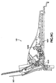
- FIG. 1 is a perspective view of one embodiment of ADF.
- FIG. 2 is a rear, left, overhead perspective view of the ADF illustrated in FIG. 1.
- FIG. 3 is a rear, right, overhead perspective view of the ADF illustrated in FIG. 1.
- FIG. 4 is a front perspective view of a main chassis of the ADF illustrated in FIG. 1.
- FIG. 5 is a rear perspective view of the main chassis illustrated in FIG. 4.
- FIG. 6A is a front perspective view of an upper chassis of the ADF illustrated in FIG. 1.
- FIG. 7 is a rear perspective view of the upper chassis illustrated in FIG. 6;
- FIG. 8A is an exploded, front perspective view of a lower chassis of the ADF illustrated in FIG. 1, including an ADF attachment hinge.
- FIG. 8B is front perspective view of the lower chassis illustrated in FIG. 8A.
- FIG. 8C is a fragmentary cross-sectional view of the lower chassis illustrated in FIG. 8A taken along line B-B.
- FIG. 8D is a front perspective view of an alternative embodiment of the lower chassis illustrated in FIG. 8A having a paper depressor element.
- FIG. 8E is a perspective view of a crossbeam of the attachment hinge illustrated in FIG. 8A.
- FIGS. 8F, 8G, and 8H are detail perspective views of retainer hooks for the attachment hinge illustrated in FIG. 8A.
- FIG. 8I is a front, right, low perspective view of the lower chassis illustrated in FIGS. 8A - 8C with the attachment hinge illustrated in FIGS. 8A, 8B, 8E, 8F, 8G, 8H mounted thereon.
- FIG. 8J is a reverse perspective of detail illustrated in FIG. 8I.
- FIG. 8K is a right, rear overhead perspective of the lower chassis with attachment hinge mounted illustrated in FIG. 8I.
- FIG. 8L is an enlarged fragmentary perspective view of the hinge attachment illustrated in FIG. 8K.
- FIG. 8M is a rear perspective view of the lower chassis illustrated in FIG. 8A.
- FIGS. 9A - 9G are schematic drawings showing a document sheet loading and unloading sequence.
- FIGS. 10A - 10B are exploded, perspective drawings of the ADF illustrated in FIG. 1 with a top case.
- FIG. 11 is a perspective drawing depicting the orientation of the ADF relative to a flat bed input device bezel.
- FIG. 12 is a perspective detail drawing depicting an input tray paper stop and pick mechanism illustrated in FIG. 4.
- FIG. 13 is a perspective view showing the paper stop and pick mechanism illustrated in FIG. 12 in situ in a home position.
- FIG. 14 is a perspective detail drawing showing the paper stop and pick mechanism illustrated in FIG. 12 in situ in a paper picking position.
- FIG. 15 is a rear, left, perspective drawing of the main chassis illustrated in FIGS. 4 and 5 showing the mounting of the paper stop and pick mechanism illustrated in FIGS. 12-14.
- FIG. 16 is a perspective overhead view of a document sheet backing mechanism illustrated in FIG. 10.
- FIG. 17 is a schematic elevation side view of the document sheet backing mechanism illustrated in FIG. 16 in the document sheet loading operational condition.
- FIG. 18 is a schematic elevation side view of the document sheet backing mechanism illustrated in FIG. 16 in the document scanning operational condition.
- FIG. 19 is a schematic elevation side view of the document sheet backing mechanism illustrated in FIG. 16 in the document sheet unloading operational condition.
- FIG. 20 is a perspective drawing of the paper drive mechanism illustrated in FIG. 10.
- FIGS. 21 - 25 illustrate the mechanical operation of the lifting mechanism.
- FIG. 26 is a section view of an ADF in accordance with one embodiment of a present invention.
- FIG. 27 is a side view of the background plate illustrated in FIG. 26.
- FIG. 28 is a perspective view of the background plate illustrated in FIG. 26.
- FIG. 29 is a plan view of the background plate illustrated in FIG. 26.
- FIG. 30 is a plan view of a scanner bezel and transparent supporting surface that may be used in combination with the ADF illustrated in FIG. 26.
- FIG. 31 is a cutaway view of the ADF illustrated in FIG. 26.
-
- The following is a detailed description of the best presently known modes of carrying out the invention. This description is not to be taken in a limiting sense, but is made merely for the purpose of illustration.
- The detailed description of the preferred embodiments is organized as follows:
- I. ADF With Movable Document Backing
- A. Overall Modular Construction
- B. Main Chassis
- C. Upper Chassis
- D. Lower Chassis
- E. Attachment Hinge
- F. Input Tray Paper Stop and Pick
- G. Paper Drive/Document Backing
- H. Paper Path
- I. Lift Cam Mechanism
- II. ADF With Stationary Document Backing
-
- The section titles and overall organization of the present detailed description are for the purpose of convenience only.
- Paper pick and feed drive software and firmware algorithms are well known in the art and beyond the scope of this description. Therefore, knowledge of a person skilled in the art is presumed and no detailed description of such is provided herein nor is such necessary for an understanding of the teachings herein.
- Referring now to the drawings and more particularly to FIGS. 1-3, 10 and 11, there is shown an
automatic document feeder 101 which is constructed in accordance with the preferred embodiment and which is adapted for use with aflat bed scanner 1101. Theautomatic document feeder 101, will be referred to hereinafter as "the ADF" for simplicity purposes. - Although in the preferred embodiment of the present invention reference is made to a
flat bed scanner 1101, those skilled in the art will understand any type of flat bed input device can be utilized, such as a flat bed copier. - The
ADF 101 is modular in nature and generally comprises a set of assemblies or chassis including a main chassis 401 (FIGS. 4-5), an upper chassis 601 (FIGS. 6A-7), and a lower chassis 801 (FIGS. 8A-8D). The threechassis medium input tray 403 best seen in FIG. 11, to amedium output tray 803 as illustrated in FIG. 8C. In understanding the preferred embodiment of the present invention, it will be helpful throughout the description that follows, to refer generally to FIGS. 10 and 11. FIG. 10 shows an exploded view of theADF 101 accompanied by an exemplary top case orouter shell 1001, while FIG. 11 illustrates the assembledADF 101 with thetop case 1001 in place relative to ageneric scanner 1101. - The three
chassis - As can be recognized from FIG. 10B, when the
ADF 101 is assembled with thetop case 1001 in place, the construct presents to the end-user a simpleinput document slot 1013, backed by aninput tray 403, where the stacked document sheets are loaded laterally, print side down, i.e., rearwardly facing. Note that the document is loaded in a "landscape" orientation regardless of the print orientation on the individual sheets. The only other feature of the assembled ADF construct apparent to the end-user is anoutput tray 803, protruding upwardly behind theinput tray 403, where collated output document pages are received from the internal paper transport mechanism following scanning or copying, for example. Output sheets are received within a gap between theinput tray 403 backside and theoutput tray 803 front side, best seen in FIGS. 2 and 3. Any control panel features which may be provided in a specific implementation, e.g., START and STOP pushbuttons, can also be provided in an accessible location on thetop case 1001. This modular construction establishes the complete input-to-output paper path. - Considering now the
main chassis 401 in greater detail with reference to FIGS. 4-5, themain chassis 401 to the extent possible for a specific implementation, is a unitary injection molded plastic part. Themain chassis 401 is provided with all the features to house the operationally functional features of theADF 101, namely motors, gear trains, shafts, paper picks and rollers, document lift assembly, and electronic controller equipment, and to establish an input paper path. Some functional features of themain chassis 401 are related to the interfit of the three chassis and paper drive mechanism and, therefore, further explanation of these features is relevant. - As best seen in FIGS. 4-5, the
main chassis 401 includes an integrally formedmain chassis shell 405 having a substantiallyplanar base 407. Aninput tray 403 rises upwardly and rearwardly from thebase 407. Theinput tray 403 has adocument receiving surface 409 that has a concave shape, in both vertical and horizontal planes. This double-concave shape assists in both properly aligning the sheets of a multi-sheet input document (not shown) and stiffening the document to facilitate sheet feeding without jamming. See also, U.S. Pat. Appl. Ser. No. 08/706,032, filed by Hong on Aug. 30, 1996, for an Image-Related Device Having Image-Medium Receiving Tray, and a Tray for Same, and a Method for Designing Such Tray, assigned to the common assignee of the present invention. More particularly, by permitting the document to conform to the concave surface shape of theinput tray 403 and having the sheet aligned in theinput tray 403 along its longitudinal edge rather than in the more conventional top or bottom edge first, causes each sheet to stiffen and thus facilitates a clean individual sheet pick. See also, U.S. Pat. No. 5,320,436, supra, col. 15, starting at line 65. A leftinput tray stanchion 411 and a rightinput tray stanchion 412, each protruding forwardly from thedocument receiving surface 409, further assist in aligning the sheets of the input document. As shown only in FIGS. 10A-10B, a sliding paper length adjuster, or simply "slider," 1005 can be mounted to theinput tray 403. - As will be explained hereinafter in greater detail, the
main chassis shell 405 includes threecavity areas cavity area 413, is a central cavity that is disposed between thecavity areas main chassis cavity 417, and a right sidemain chassis cavity 419. - In order to facilitate the specific implementation design expedients, the construct of the
shell 405 includes a group of upper right side interfit features 415 and a group of left side interfit features 416. The right group of interfit features 415 is disposed on the right side of the main chassiscentral cavity area 413, while the left group of interfit features 416 is disposed on the left side of the main chassiscentral cavity area 413. The configuration of the groups of interfit features 415 and 416 facilitates the construct of themain chassis 401 in a fast and efficient manner. In this regard, as best seen in FIGS. 10A-10B, theupper chassis 601 mates between the interfit features 415 and 416 permitting theupper chassis 601 to easily drop into thecentral cavity area 413 of themain chassis 401. Moreover, the rear side of themain chassis 401 is also configured to matingly engage thelower chassis 801. Thus, thelower chassis 801 is easily mounted on the rear side of themain chassis 401 by a set of four screws such asscrew 1010. In this regard, as best seen in FIG. 5, a set of molded screw retainer bushings, such as abushing 50, are provided to align where thelower chassis 801 is screw mounted to themain chassis 401. - When the
upper chassis 601 is set in place relative to themain chassis 401, a sheet feed gap is created between theinput tray surface 409 and a rear portion of theupper chassis 601 at about thecentral cavity area 413. Document sheets loaded into theinput tray 403 drop sequentially in seriatim through this gap to travel onto the supporting surface of the flatbed input device 1101 as will be explained hereinafter in greater detail. Similarly, when thelower chassis 801 is mounted in place relative to themain chassis 401, a sheet receiving gap is created between thelower chassis 801 and the lower rear of themain chassis 401. - Considering now the left side
main chassis cavity 417 in greater detail with reference to FIG.4, thecavity area 417 is sufficiently large in volume to receive therein a leftside stepper motor 103. Thestepper motor 103 is mounted within thecavity area 413 by and suitable mounting devices, such as the mountingdevices 1010. Thecavity area 417 is open outwardly from thecentral cavity area 413 in order to facilitate ease of assembling thestep motor 103 within thecavity 417. - Considering now the right side
main chassis cavity 419 in greater detail with reference to FIG. 5, the rightside cavity area 419 also has a sufficiently large volume to receive therein a rightside stepper motor 301, that is substantially similar in construction to the leftside stepper motor 103. The rightside stepper motor 301, like the leftside stepper motor 103 is mounted within thecavity area 419 byconventional mounting devices 1010. - As will be explained hereinafter with reference to FIGS. 10A-10B and FIG. 12, other mechanical elements of the
ADF 101, such as a gear train ortransmission arrangement 1009, apaper pick 1201 and apaper drive shaft 1203, are coupled to therespective stepper motors stepper motors controller 1003. Thecontroller 1003, as best seen in FIG 10B is configured in the form of a printed circuit board having electrical cabling indicated generally at 1007 that interconnects electrically thecontroller 1003 with themotors ADF 101. The printed circuit board is dimensioned to be received within afront cavity area 421 of themain chassis 401. - Considering now the
upper chassis 601 in greater detail with reference to FIGS. 6A and 7, amain cross beam 603 is positioned to traverse the main chassisfirst cavity 413 parallel to the input tray 403 (FIGS. 1-3 and 10). Aleft side cantilever 607 and aright side cantilever 608 extend forwardly from each end of thecross beam 603. Eachcantilever upper chassis 601 is a unitary injection molded plastic piece part; molding features and interfit features will be specific to a particular design implementation. Theupper chassis 601 is also secured to themain chassis 401 withconventional fasteners 1010 as shown in FIGS. 10A-10B. - As shown in FIG. 7, the rear of the
cross beam 603 is provided with a plurality of protrudingfins 605. When theupper chassis 601 is mounted into themain chassis 401, thefins 605 are in close proximity to theinput tray surface 409 as seen in FIG. 3. When a document is loaded into theinput tray 403, the document sheets are held between theinput tray surface 409 and theupper chassis fins 605. - Molded leaf spring features 609, 610 are provided to retain a transfer shaft 2003 (FIG. 20) using
bushings upper chassis 601 using molded capture bearings and a bushing (not shown) and another molded leaf spring 622 (FIG. 7) provided to retain a bushing (not shown). Theseparator shaft 628 bears a fixedly mounted central paper separator wheel 631 (FIG. 9A). One end of theseparator shaft 628 is coupled to a motor (not shown in this FIG.) via gearing 633 (FIG. 2) and is driven during a paper feed cycle. - A spring retainer 611 (FIG. 6A) holds a compression spring (not shown). As shown in FIG. 10A, a
tray sensor 701 and apick sensor 703 as would be known in the art. - The
lower chassis 801 is shown in further detail in FIGS. 8A - 8L, along with a quickrelease attachment hinge 821. The entirelower chassis 801 is a unitary injection molded plastic part. Like theinput tray 403, and as best seen in FIG. 8C, adocument output tray 803 has asurface 805 that provides a shallow concave curvature in a short height form factor -- in the dimensional region of half the paper width, e.g., approximately one-half that of an A-size to legal size paper sheet equal to about 4.25 inches. Again this takes advantage of paper stiffness induced when it is shaped into a semi-cylindrical form along its longitudinal axis. Thus, this embodiment can have a lower height form factor that no longer needs to support a remaining half of a document sheet by requiring such well known prior art mechanisms as output tray pull-out extensions, wire frame clips, or the like. Returning to FIGS. 8A and 8B, an upper chassis leftstanchion 807 and an upper chassisright stanchion 808 are integrally molded parts of thelower chassis 801, protruding forwardly from theoutput tray surface 805. As shown in FIG. 10A, the twostanchions lower chassis 801 via appropriately molded interfit features to themain chassis 401 with fasteners 1010any suitable known or proprietary type. - Along the lower edge of the
output tray 803, a document sheet output guide andshelf 809 extends forwardly. Output traypaper guide fins 811 protrude upwardly from theshelf 809 to lift the leading lateral edge of a sheet of output paper, directing it to follow along theoutput tray surface 805. - As best seen in FIGS. 2 and 3, the
output tray 803, like theinput tray 403, has a substantially vertical orientation. The gap between the twotrays - In an alternative embodiment as depicted in FIG. 8D, a
paper depressor 813 is added to the central region of thesurface 805 of theoutput tray 803. To mount the paper depressor,lower extremities 815 are formed to snap-fit to the paper pick and stop shaft 1203 (as shown in FIG. 15). Thepaper depressor 813 is made of a low friction material such as commercially available Cycoloy™, made by the General Electric company of One Plastics Avenue, Pittsfield, MA 01201. This design has been proven to work reliably for plain papers from 16-pound to 24-pound types at any acute angle less than forty-fives degrees to vertical as long as the output tray height is at least one-half the document sheet length. With thepaper depressor 813, the paper sheets are forced into a cylindrical shape and stiffened. Without thedepressor 813, the output tray angle to vertical should be reclining sufficiently to retain the paper sheets upright. - Considering now the quick
release attachment hinge 821 in greater detail with reference to FIG. 8A, thehinge 821 enables themodular chassis flat bed scanner 1101 with a precisely aligned document feed path relative to the supporting surface of thescanner 1101. Thehinge 821 facilitates at least two different ADF/scanner orientations for document scanning purposes coupled with a quick release feature for disconnecting theADF 101 from thescanner 1101. In this regard, as shown in FIG. 8A, thelower chassis 801 serves as a mount for theADF hinge 821. As shown in FIG. 11, thisattachment hinge 821 provides a dual purpose mechanism, both for mounting the assembled threechassis ADF 101 to either a compatible copier or scanner or to abezel 1101 adapted to overlay such a copier or scanner flat bed scanning surface and for raising and lowering the ADF off a flat bed bezel without removal of the entire ADF system. - Returning to FIGS. 8A and 8E - 8H, a
crossbeam 823 is provided with a set ofhinge axle retainers Axle retainers axle retainers lower chassis 801 is provided with threeaxle casings attachment hinge axles 834 are provided to swivel mount theattachment hinge 821 to thelower chassis 801 in the shown manner via the axle retainers 825 - 830 and axle casings 831 - 833 with each of the axle casings riding an axle between a complementary pair of reversed-facing axle retainers, e.g., thecasing element 831 is betweenretainer elements - As shown in FIGS. 8A and 8F - 8H, a pair of
attachment hinge flanges 835 are mounted to theattachment hinge 821 bysuitable fasteners 1010 and depend from thecrossbeam 823. As shown in FIG. 11, in combination with thecrossbeam 823, theflanges 835 are used to mount the assembled ADF to either a compatible copier orscanner 1101 or to a bezel adapted to overlay such a copier or scanner flat bed scanning surface. Theflanges 835 are provided with dimensions sufficient not only to provide a steady, accurate aligning of the ADF, but also with a length sufficient to allow for lifting of the ADF vertically without removing the entire ADF from thescanner 1101 or flat bed, such as when the document pages to be scanned are in a book or magazine. To facilitate this function, the lower extremity of thehook 835 us provided with aflexible hook 837 adapted to catch a complementary lip or edge of the bezel or scanner flange receiving slots (see e.g., FIG. 11, sleeve 1103). - As the ADF is swivel mounted to the
hinge 821, ADF tilt-up stops are provided to facilitate use of the ADF. FIG. 8B shows that the bottom of the lower chassis output document sheet guide andshelf 809 is provided with depending ADF tilt-up stops 841. FIG. 8E shows that thecrossbeam 823 of theattachment hinge 821 is provided with rising protrusions that form complementary, hinge tilt-up stops 842. The tilt-up stops 841, 842 in the preferred embodiment are matched such that a 65-degree rotation upward of the ADF is permitted (see detail plane B -- B, FIG. 8B). FIGS. 8I - 8L depict the interfit of the hinge features with the lower chassis features. FIG. 11 shows theADF 101 at its upwardly tilted position relative to thescanner 1101. Note that this also facilitates mounting the ADF to a scanner provided with appropriate flange slots or ascanner 1101 with receivingsleeves 1103. - Paper pick and transport mechanisms are also housed by the
main chassis 401. FIG. 12 shows an embodiment of input tray paper stop and pickmechanism 1201. - FIG. 13 shows the
paper stop mechanism 1201 mounted in position with respect to theinput tray 403 with the mechanism in a paper loading, or "home," position; the upper chassis is not shown in position in this drawing. FIG. 14 shows the paper stop and pickmechanism 1201 mounted in position with respect toinput tray 403 with the paper stop and pick mechanism in a "retracted" position as it would be during a paper picking operation. - Centrally mounted on a paper pick and stop
shaft 1203 is apaper pick roller 1205. Thepaper pick roller 1205, generally having a rubber or grit wheel surface, is mounted via a fixedbearing hub 1207. A pair of spaced apart spring loaded paperstop fence devices 1209 are mounted on opposite sides of thepick roller 1205. Thestops 1209 protrude into the paper path (P) and support from below a stack of sheets of paper (not shown) loaded into theADF 101. As an individual sheet is picked form the stack by thepick roller 1205, thestops 1209 temporarily rotate out of the paper path allowing the picked single sheet to fall under the force of gravity from the stack to start a journey along the paper path to theoutput tray 801 as will be explained in greater detail. Once the picked sheet has cleared thestops 1209, thestops 1209 snap back into the their original resting positions to support from below any remaining sheets in the stack. - The
stop fence devices 1209 are mounted on theshaft 1203 and further help to minimize teetering of the paper stack on thepick roller 1205. Considering now thepaper stop device 1209 in greater detail with reference to FIG. 12, each paperstop fence device 1209 includes ahousing 1211, a one-way needle clutch 1213, and a biasingtorsional spring 1215, biasing the device toward its home position as depicted in FIG. 13. Thehousing 1211 has extended paperstop fence tabs 1217. Thetorsional spring 1215 provides enough force on thehousing 1211 such that thetabs 1217 can support a number of sheets of a document (e.g., 50 sheets of legal size paper of up to 24-pound type). In operation, when a document is loaded (see arrows labeled "P") into the input tray, face down - i.e., with the print side facing input tray surface 409 - the paper sheets (not shown) have their side edges sitting on the top edges of the paperstop fence tabs 1217 which are protruding substantially horizontally through alignedapertures 1301 provided in thesurface 409 of theinput tray 403. Similarly, anaperture 1303 is provided in theinput tray surface 409 for thepaper contact surface 1206 of thepick roller 1205 to extend forwardly of theinput tray 403. - A paper
pick drive shaft 1203 connects the paper stop and pickmechanism 1201 to astepper motor 103. Turning briefly to FIG. 15, the mounting of thedrive shaft 1203 to amotor 103 is made withstandard bushings 1501. - As a sheet of paper is center-picked, the force of a moving document sheet imparted by the
pick roller 1205 is sufficient to release the clutch 1213 and push thetabs 1217 out of the way as shown in FIG. 14. Thetorsional spring 1215 causes thetabs 1217 to bounce back to the home position after the trailing edge of the paper clears the outermost point on the tabs. In other words, by adding a paper stop and pickmechanism 1201, the present invention takes advantage of thevertical input tray 403 in that paper falls into the pick roller by gravity, eliminating the need for pre-picking mechanism. - A paper drive and document backing mechanism is mounted to the under-carriage of the
main chassis 401. FIG. 16 shows an assembled paper drive2001 (detailed in FIG. 20) and adocument backer 1601, referred to in the assembled combination as apaper pressure mechanism 1611. - The ADF described herein uses the technique of sequentially loading and unloading original document sheets onto the scanner flat bed glass 1701 (FIGS. 17 - 19) using a document backing method taught in U.S. Patent Application Ser. No. 08/651,066 (Hendrix et al.), supra. In order to provide the highest quality scanned version, it is desirable to press the document sheets firmly against the
glass 1701 of the scanner. The assembly forming adocument backer 1601 includes alift plate 1603 is a substantially rigid, planar material, such as a molded ABS plastic. Mounted on the lower surface of thelift plate 1603 is afoam rubber pad 1605, preferably of polyurethane, commercially available from Boyd company of 13885 Ramona Avenue, Chino, California, providing a document backing pressure pad for a document sheet on thescanning bed glass 1701 at a scanning station. To the lower surface tension of the foam pad, athin plastic film 1607 preferably of polycarbonate film, trade name "Lexan", commercially available from General Electric company of One Plastics Avenue, Pittsfield, MA 01201, is provided to act as a low-friction contact with document sheets. - The combination of materials used in the
document backer assembly 1601 and the lifting of the assembly during loading and unloading of print media sheets from the flat bed of a scanner, or bezel, not only reduces the friction, but also minimizes the electrostatic buildup, improving reliability of sheet feeding. - In the preferred embodiment, the
document backing assembly 1601 is mounted to the undercarriage of themain chassis 401 by slipping the assembly through the main chassisfirst cavity 413. Thedocument backing assembly 1611 is inserted through thefirst cavity 413 of themain chassis 401; front hooks 1610, 1612 mate with molded features of the main chassis under carriage toward the front thereof;spring 1614 loadedbushings 1613 are provided to hold thedocument backing assembly 1601 in molded features of the main chassis toward the rear thereof, adjacent thefirst cavity 413 as shown in FIG. 10A. The embodiment solves the problem of getting a document sheet between theglass 1701 and theplastic film 1607 by lifting the assembledpaper drive 2001 anddocument backer 1601 as the document sheet is loaded and unloaded from the glass. Alift cam mechanism 1609 moves between: - 1. a forward position as shown in FIG. 17, lifting the
document backing assembly 1601 to permit a sheet of paper to enter between the assembly and thescanner bed glass 1701 as indicated byarrow 1611, - 2. a central position as seen in FIG. 18, dropping the
document backing assembly 1601 onto thescanner bed glass 1701, and - 3. a rearward position as shown in FIG. 19, lifting the
document backing assembly 1601 to permit a sheet of paper to be driven off thescanner bed glass 1701 as indicated byarrow 1613. -
- The
cam lift mechanism 1609 will be described hereinafter in greater detail. - FIG. 20 shows detail of the
paper drive mechanism 2001. Thereversible stepper motor 301 is coupled to a transfer shall 2003 via a conventional gear train, or other transmission, 2005. A pair ofpaper drive rollers drive roller axle 2009. The paperdrive roller axle 2009 has spring-loadedmountings main chassis 401 structure as depicted in FIG. 15. Agear train linkage 2013 is used to turn thepaper drive rollers axle 2009 at the approximate midpoint of the axle. Thegear train linkage 2013 moves with the axle and pivots about thetransfer shaft 2003. Note that both themotor 301 and thetransfer shaft 2003 is rigidly mounted to the ADFmain chassis 401 structure. As a result of this configuration, the normal force of the twodrive rollers drive axle 2009 coupled to the system transmission system activates theelastomeric drive roller flat bed scanner 1101 without any substantial paper skew. Thegear train linkage 2013 is used to provide motion to a lift cam during paper loading and unloading to hoist thedocument backer 1601 off the glass (FIGS. 17 and 19). - FIGS. 9A-9G depict the dynamics of the paper path established by the
main chassis 401,upper chassis 601 andlower chassis 801. In this embodiment, abezel 902 is attached to theapparatus 101. FIG. 9A shows theapparatus 101 in the condition where adocument sheet 901 is loaded. The paper stop and pickmechanism 1201 is in the position shown in FIG. 13, and thedocument sheet 901 is resting on the two paper stop and pickmechanisms 1201 andpaper pick roller 1205. Thelift cam mechanism 1609 is in the same position as shown in FIG. 18, with thedocument backing assembly 1601 in its lowered position. - FIG. 9B demonstrates pertinent apparatus feature positions during a paper pick operation. The
paper pick roller 1205 is motor-activated, turning so as to pull thesheet 901 downward into the tray. Thesheet 901 is fed downward and shaped between theinput tray surface 409 and theupper chassis 601fins 605. Thetabs 1217 of the paper stop and pickmechanism 1201 are moved out of the way by thesheet 901 as described with respect to FIG. 12. Theleading edge 903 ofsheet 901 is directed toward thedrive rollers drive rollers leading edge 903 ofsheet 901 and direct it toward the scanning station, also moves thecam mechanism 1609 to its forward position, lifting thedocument backing assembly 1601 such that the sheet will slip underneath. - During a paper pick cycle, as shown in FIG. 9C, the
leading edge 903 of thesheet 901 contacts the surface of the glass bed before reaching thedrive rollers glass 1701 and before reaching thedrive rollers - Turning to FIG. 9D, the
drive rollers glass 1701. The trailing edge ofsheet 901 remains in contact with thedrive rollers document backing assembly 1601 onto thesheet 901. - Following scanning, as shown in FIG. 9F, the
drive rollers lift cam mechanism 1609 is moved to its rearward position as shown in FIG. 19, lifting thedocument backing assembly 1601 to permit a sheet ofpaper 901 to be driven off theglass 1701. The trailing edge of thesheet 901 that had been retained under thedrive roller shelf 809 receives theexit leading edge 905. The sheet is driven between the output tray drive rollers 1503 (see also FIG. 15). The outputtray drive rollers 1503 directs thesheet 901 upwardly into theoutput tray 803 where it is retained behind theshelf 809 as shown in FIG. 9G. Thelift cam mechanism 1609 is returned to its center position. - Referring now to the drawings and more particularly to FIGS. 9A-G and 21-25 there is shown a
lift cam mechanism 1609 that facilitates the lifting of an assembledpaper drive 2001 anddocument backer 1601 during the loading and unloading of a document sheet onto the transparentglass supporting surface 1701. In this regard, thelift cam mechanism 1609 solves the problem of transporting such a document sheet between the supportingsurface 1701 and theplastic film 1607 during such loading and unloading operations. - Considering now the
lift cam mechanism 1609 in greater detail with reference to FIGS. 9A-G and 21-25, thelift cam mechanism 1609 generally includes a cam linkage indicated generally at 1615, and a differential gear train arrangement indicated generally at 1617. Thecam linkage 1615 and the differentialgear train arrangement 1617 in combination facilitate a passive automatic lifting action of thedocument backer 1601 to substantially reduce friction and electrostatic build up for reliable sheet feeding purposes. - As best seen in FIGS. 21-25, the
cam linkage 1617 generally includes an elongated transfer shalt 2003 that is supported for rotational movement between a motor plate 1619 and thechassis 401. A pair of transfer gears, 8001 and 8002 respectively, are pressed mounted spaced from one another on theshaft 2003 to facilitate a lifting action enabled by a freespinning lift cam 8005 that will be described hereinafter in greater detail. - The
transfer gear 8001 has a larger diameter than thetransfer gear 8002 and is mounted relative to theshaft 2003 so that it engages a motor pinion gear 1621 extending from thedrive motor 103. In this manner, the motor pinion gear 1621 translates the rotational drive of themotor 103 to thetransfer gear 8001 that in turn causes theshaft 2003 to be rotated about it axis at a desired rotational speed. - The
lift cam 8005 and a free spinningtransfer idler gear 8003 are mounted inwardly of thetransfer gear 8002 on theshaft 2003. Theidler gear 8003 and thelift cam 8005 are slightly spaced from one another with thelift cam 8005 being mounted furthest from the distal end of theshaft 2003. An elongatedlift cam pin 8006 is mounted fixedly by wedging to thelift cam 8005 and extends outwardly therefrom parallel to theshaft 2003. Mounted to the distal end of thelift cam pin 8006, is a free spinning liftcam composite gear 8004, having a small diameter portion and a large diameter portion. The small diameter portion engages theidler gear 8003 and the large diameter portion engages thetransfer gear 8002. - In order to move a document onto and off the scanner bed
glass supporting surface 1701, a freespinning drive roller 2007 is pressed mounted to adrive shaft 2009 having a press fitteddrive gear 8008 mounted to its distal end. Thedrive shaft 2009 is mounted spaced from and parallel with thetransfer shaft 2003 and is supported between the motor plate 1621 and a freespinning cluster housing 8010. Thecluster housing 8010 mounted inwardly of thedrive gear 8008 and is supported on and between thetransfer shaft 2003 and thedrive shaft 2009. Thecluster housing 8010 has fixed thereto anelongated housing pin 8009 that extends outwardly therefrom in a plane parallel with theshafts housing composite gear 8007 is mounted on thepin 8009 betweenshafts composite gear 8007 includes a large diameter portion that engages thedrive gear 8008 and a small diameter portion that engages thetransfer idler gear 8003 to further facilitate a lifting action as will be hereinafter described. - As best seen in FIGS. 24-25, the
lift cam 8005 includes a pair of spaced apart stops 8005A and 8005B that limit the movement of thelift cam 8005 as will be explained hereinafter in greater detail. - Considering now the operation of the
lift cam mechanism 1609 with reference to FIGS. 9A-G and 21-23, thelift cam 8005 begins in a down position as best seen in FIG. 21. As the motor pinion gear rotates in a clockwise direction in engagement with thetransfer gear 8001, thetransfer gear 8001 imparts a counter clockwise rotation to thetransfer shaft 2003. Thetransfer shaft 2003, in turn, causes thelift cam 8005 to lift and to move to a final lifted position as shown in FIG. 22. - More particularly, as the
transfer gear 8002 is fixed to theshaft 2003, thegear 8002 rotates in the same counter clockwise direction and at the same rotational speed as that of theshaft 2003. Theidler gear 8003, however, remains in a fixed position due to the friction between thedrive roller 2007 and thescanner glass bed 1701. In this regard, theidler gear 8003 locks the gear train ofgears gears drive shaft 2009, its associateddrive roller 2007 andcluster housing 8010 also remain fixed in their respective positions. However, the free spinning liftcam composite gear 8004, rides along thetransfer gear 8002 and theidler gear 8003, and rotates in response to cause thelift cam 8005 andlift cam pin 8006 to move in unison, pivoting in a clockwise direction relative to thetransfer shaft 2003. - Once the
lift cam 8005 has moved to its final lifted position as illustrated in FIG. 22, thedrive roller 2007 starts driving the document forward. More particularly, thedrive roller 2007 imparts motion to the document in the following manner. Motion of thelift cam 8005 is inhibited by thestops lift plate 1603. With the lift cam in a fixed position, the liftcam composite gear 8004 continues to rotate onpin 8006 in a clockwise direction that now in turn, imparts a rotational motion to the geartrain comprising gears gear 8003 is rotated in a counter clockwise direction, which motion is coupled to thedrive gear 8008 via the clockwise motion ofgear 8007 aboutpin 8009. From the foregoing, it should be understood that the document is now pulled forward under the frictional force of thedrive roller 2007. Thedrive roller 2007 rotates in a counter clockwise direction due to thecluster housing 8010 being held in a fixed position, while thegear 8007 rotates aboutpin 8009 to impart rotational motion to drivegear 8008 andshaft 2009. - After the document has been moved into a proper position for scanning, the
lift cam 8005 is moved to its original down position as illustrated in FIG. 21. In this regard, thetransfer shaft 2003 starts to rotate in an opposite clockwise direction, that in turn, causes thetransfer gear 8003 to rotate in the same clockwise direction. The liftcam composite gear 8004 riding alonggears lift cam 8005 and its associatedpin 8006 to pivot on thetransfer shaft 2003. Motion of thedrive roller 2007,drive shaft 2009 and thecluster housing 8010 remain fixed as no rotation motion is imparted viagears transfer shaft 2003 via thetransfer gear 8001. The rotation of thetransfer shaft 2003 causes thetransfer gear 8002 to rotate in the same direction at the same rotational speed, while theidler gear 8003 remains in a stationary position. Again, the friction between thedrive roller 2007 and the document locks the gear train comprising thegears lift cam 8005 remains in a fixed position while the document is scanned. - After the document has been scanned, the
lift cam 8005 is lifted to permit the document to be moved off of thescanner glass bed 1701. In this regard, the motor pinion gear is rotated in a counter clockwise direction that in turn imparts a clockwise rotation to thetransfer shaft 2003 and thetransfer gear 8002. That isshaft 2003 rotates via the engagement of thetransfer gear 8001 with the motor pinion gear, and thegear 8002 rotates as it is fixed to theshaft 2003. As explained earlier, the friction between thedrive roller 2007 and the document locks the gear train ofgears - The
lift cam 8005 then begins to lift. Thecomposite gear 8004 free spins onpin 8006 and rides alonggears lift cam 8005 and its fixedpin 8006 to pivot about thetransfer shaft 2003. Thedrive roller 2007, and driveshaft 2009 however remain in a fixed position. In this regard, thehousing cluster 8010, and gears 8007, 8008 remain fixed thus, no rotational motion is imparted to thedrive shaft 2009. The final lifted position of thelift cam 8005 is illustrated in FIG. 23, where thestop lift cam 8005. - Once the
lift cam 8005 has been lifted to its final position as illustrated in FIG. 23, the document is now ejected out from its supporting position on thescanner glass bed 1701. In this regard, while the transfer shalt continues to rotate in a clockwise direction, the liftcam composite gear 8004 rotates in a stationary position counter clockwise aboutpin 8006. The rotation ofgear 8004 is imparted togear 8007, which in turn rotates thedrive gear 8008,drive shaft 2009 and driveroller 2007 in a clockwise direction. In this manner, the clockwise rotation of thedrive roller 2007 moves the document off thescanner bed 1701 in a reverse direction. - After the document has been removed from the
scanner bed 1701, the pinion gear rotational direction is reversed, which in turn, causes thetransfer shaft 2003 to rotate in a counterclockwise direction. The counter clockwise rotation of theshaft 2003 imparts motion to thelift cam 8005 to return it to a down position. More particularly, thecomposite gear 8004 rotates in a clockwise direction and rides alonggears lift cam 8005 and its associatedpin 8006 to pivot about thetransfer shaft 2003. The friction between thedrive roller 2007 and theglass scanner bed 1701 locks thegear train lift cam 8005 comes to rest in it down position read for the next document. - From the foregoing, it should be understood by those skilled in the art that the
lift cam 8005 is driven in a predetermined sequence that starts with thelift cam 8005 being position in a down position as illustrated in FIG. 21 and ending in the same down position. The sequence includes: - 1. moving the
lift cam 8005 upwardly from a down position to an extended position that permits the document to be moved onto thescanner bed 1701; - 2. driving the document onto the
scanner bed 1701 via thedrive roller 2007; - 3. lowering the
lift cam 8005 to its down position prior initiating a scanning operation; - 4. waiting for the document scanning operation to be completed;
- 5. moving the
lift cam 8005 upwardly from the down position to the extended position to permit the document to be moved off of thescanner bed 1701; - 6. driving the document in a reverse direction off the
scanner bed 1701; and - 7. lowering the
lift cam 8005 to its down position to wait for another drive/eject cycle. -
- The
ADF 101 described above and illustrated in FIGS. 1-25 includes adocument backing assembly 1601 that is lifted and lowered during the loading and unloading of a document onto the transparent supportingsurface 1701. Lifting and lowering are accomplished though the use of thelift cam mechanism 1609 illustrated in FIGS. 9A-G and 21-25. As illustrated for example in FIG. 26, anADF 2100 in accordance with a preferred embodiment of another aspect lacks thedocument backing assembly 1601 andlift cam mechanism 1609 and, instead, includes astationary background plate 2102. TheADF 2100 is otherwise substantially identical to theADF 101 and common elements are identified by common reference numerals. - The
background plate 2102 is located above the transparent supportingsurface 1701. Referring more specifically to FIGS. 27-29, theexemplary background plate 2102 includes aplate member 2104 and a plurality of downwardly extendingsupport members 2106a-c that support the plate member on a scanner, such asscanner 1101, above the transparent supportingsurface 1701. Theplate member 2104 includes aplanar portion 2108 and acurved portion 2110. The distance between theplate member 2104 and the transparent supportingsurface 1701 is large enough to allow adocument 901 to be fed on to and off of the transparent supporting surface without moving thebackground plate 2102, yet small enough to prevent shadowing effects. The distance between the transparent supportingsurface 1701 and the bottom of theplate member 2104 in the illustrated embodiment is about 1.0 mm at therearward end 2112 and about 0.5 mm at theforward end 2114. Thesupport members 2106a-c are sized to provide this spacing. - Supporting the
background plate 2102 in this manner provides a number of advantages. Most notably, thebackground plate 2102 need not be raised when a document is fed onto the scanner, lowered prior to scanning, and then raised again so that the document can be removed. The need for a lifting mechanism, such as the aforementionedlift cam mechanism 1609, which includes the two-part lift cam 8005,lift cam pin 8006,composite gear 8004, andtransfer gear 8002, is therefore eliminated. The need for a three part document background plate, such as theaforementioned background plate 1601, which includes alift plate 1603, afoam rubber pad 1605, and a low-friction film 1607, is also eliminated. As a result, use of the present background plate greatly reduces component and assembly costs. Assembly costs are further reduced because thebackground plate 2102 is not coupled to the paper drive mechanism illustrated in FIG. 20. This allows the paper drive mechanism to be inserted through the top of the chassis, which is much easier than the prior insertion method that required a number of difficult manipulations of the chassis so that the paper drive mechanism could be installed through the center of the chassis with the chassis tilted upwardly. - Although the
exemplary plate member 2104 is supported on the scanner at four points, there are only threesupport members 2106a-c in the illustrated embodiment. The reason is as follows. As shown by way of example in FIG. 30, athin polycarbonate label 2116 rests on top of the transparent supportingsurface 1701. Thelabel 2116, which is approximately 0.5 mm thick, is used to define the left scanning limit and includes indicia that allows users who are not using the ADF to properly align letter size (A) and European size (A4) documents on thetransparent supporting structure 1701. [Note that legal size (L) documents are fed with the ADF transverse to letter (A) and European (A4) documents and that the legal size (L) documents are scanned in a two step process.] To offset the 0.5 mm thickness of thelabel 2116, the height ofsupport member 2106a, which rests on the label, is 0.5 mm less than that ofsupport member 2106b, which rests of the transparent supportingsurface 1701. The height of a fourth support member (shown in dashed lines) would be 0.5 mm less than the height ofsupport member 2106c, which also rests on the transparent supportingsurface 1701. In the illustrated embodiment, however, the thickness of thelabel 2116 is equal to the height of thesupport member 2106c, thereby eliminating the need for a fourth support member. The distances betweensupport members document 901 shown in dash lines to pass therebetween. - The
exemplary background plate 2102 also includes an attachment system that allows the background plate to be easily secured to the ADF chassis. The exemplary attachment system illustrated in FIGS. 27-29 and 31 secures thebackground plate 2102 to the ADF chassis at four points by way of a pair ofrearward latch elements 2118 and a pair offorward latch elements 2120. The rearward andforward latch elements forward protuberances 2122 and 2124 (FIG. 31) within the chassis during assembly and disassembly. In the illustrated embodiment, therearward protuberances 2122 are rectangular, while theforward protuberances 2124 are cylindrical. Thelatch elements ramps latch elements protuberances - The exemplary attachment system also allows the
background plate 2102 to move slightly relative to the ADF chassis. Such movement insures that thesupport members 2106a-c will rest on the scanner despite minor variations in the relative positions of the ADF and scanner and/or minor warping in thebackground plate 2102. For example, the ADF chassis may be configured such that therearward latch elements 2118, which rest on top of therearward protuberances 2122, are free to move about 4 mm above the protuberances. Additional movement is prevented by the upper stops 2131 (FIG. 31) on the main chassis and thesteps 2150 on thebackground plate 2102. The exemplaryforward latch elements 2120 includeobround apertures 2130 into which the cylindricalforward protuberances 2124 extend. The height of theapertures 2130 is preferably about 1.5 mm greater than the diameter of theprotuberances 2124 so as to allow for small amounts of movement. The small amount of relative movement allows wrinkled sheets to pass through the ADF without jamming and also provides relief for tolerances created by the mating of thebackground plate 2102 and chassis as well as warping of the background plate. - As illustrated for example in FIGS. 27-29, a pair of
spacing tabs 2132 are used to restrict the lateral positioning of the forward portion of thebackground plate 2102 to prevent disengagement of theforward latch 2120 during shipping. - The
exemplary background plate 2102 is provided with a pair of openings 2136 (FIG. 28) that allow thedrive rollers 2007 and 2008 (FIG. 20) to extend though theplate member 2108, a pair ofabutments 2134 on either side of one of the openings and a pair of supports 2138 (FIGS. 27-29). Theabutments 2134, which are spaced approximately 0.5 mm from the associated drive roller hub, allow the drive roller to control the position of the plate. The position of the drive roller is, in turn, controlled by the position of thedrive roller axel 2009 which is secured to the chassis with a bushing arrangement. - The
supports 2138 are used to prevent excess travel of thedrive roller axle 2009 caused by forces applied to thedrive rollers drive roller axel 2009 is allowed to move a small distance in order to compensate for differences in document thickness. Thesupports 2138 and driveroller axle 2009 are positioned relative to one another such that the drive roller axle will contact the supports after the drive roller axel moves beyond that distance, thereby preventing disengagement of the drive roller axel from the bushing arrangement. - The rearward region of the
background plate 2102 also includes a plurality of paper size sensor openings 2140 (FIGS. 28 an 29) in a predetermined pattern. The papersize sensor openings 2140 are used by the scanner to distinguish between letter (A) and European (A4) sized documents. After the document has been fed onto the transparent supportingsurface 1701, the image scanner focuses on the area including the papersize sensor openings 2140. The papersize sensor openings 2140 will be covered in those instances where a letter (A) sized document is present. [Note the relative positioning of the letter (A) and European (A4) documents in FIG. 30.] This provides the system controller with an indication as to the size of the document being scanned and, because it does so with image scanner, eliminates the need for an additional sensor. - One important consideration associated with the use of the present
stationary background plate 2102, which is preferably formed from plastic materials such as polystyrene, styrene copolymer or HIPS, is static electricity. A buildup of static electricity can interfere with movement of the documents. To that end, and as illustrated for example in FIGS. 27 and 29, theexemplary background plate 2102 includes agrounding post 2142 that may be connected to a ground, such as the ground on the ADF's printed circuit assembly. Thegrounding post 2142 is provided with aneyelet 2144 for a screw that is used to connect a drain cable (not shown) to the grounding post. Static may be reduced by combining an anti-static additive with the plastic material which makes the plastic conductive and allows charges to drain to thegrounding post 2142. A suitable anti-static additive is the Variant Additive Concentrate (product no. CSY9301A) from Clariant/North America. The anti-static additive is between about 3% and 6%, and preferably about 4%, of the plastic/anti-static additive mixture. - In many scanners, such as scanner the
exemplary scanner 1101, the transparent supportingsurface 1701 is a glass plate. The exposed sharp edges of the glass plate must be beveled in order to prevent injury to users. Alternatively, a portion of the bezel can be used to cover the sharp edges. When used in combination with thepresent background plate 2102, the bezel will be provided with cut-outs for thesupport members 2106b-c. In addition, theplate member 2104 will include abevel edge 2146 to accommodate the edge of the bezel, as is illustrated for example in FIG. 28 to prevent shadowing effects during the scanning of a document. - Many modifications and variations will be apparent to practitioners skilled in this art. For example, in lieu of injection molded plastic, the chassis are amenable to sheet metal stamping or other known fabrication techniques. Similarly, any process steps described might be interchangeable with other steps in order to achieve the same result.
- The disclosures in United States patent application no. 09/395,018, from which this application claims priority, and in the abstract accompanying this application are incorporated herein by reference.
Claims (8)
- An automatic document feeder for use with a scanning device (1101) including a substantially transparent document support (1701), the automatic document feeder comprising:a chassis (401) designed to be secured relative to the scanning device (1101);a plate member (2104) secured to the chassis (401); anda plurality of support members (2106) depending from the plate member (2104) and operable to support the plate member (2104) on the scanning device (1101) in spaced relation to the transparent document support (1701).
- A feeder as in claim 1, wherein the document feeder is operable to fed documents in a feed direction, the plate member (2104) forming a rearward portion and a forward portion in the feed direction, and the support members (2106) supporting the plate member (2104) such that the rearward portion of the plate member (2104) is separated from the transparent document support (1701) by a first distance, the forward portion of the plate member (2104) being separated from the transparent document support (1701) by a second distance, the first distance being greater than the second distance.
- A feeder as in claim 2, wherein the first distance is approximately twice the second distance.
- A feeder as in claim 1, wherein the document feeder is operable to fed documents in a feed direction, the plate member (2104) forming a rearward portion and a forward portion in the feed direction, the rearward portion including an upwardly curved member (2110).
- A feeder as in claim 1, wherein the plate member (2104) is secured to the chassis (401) by an attachment system operable to secure the background plate to the chassis (401) in such a manner that the background plate can move relative to the chassis (401).
- A feeder as in claim 5, wherein the attachment system comprises a plurality of latch elements (2118, 2120).
- A feeder as in claim 6, wherein the chassis (401) includes a plurality of protuberances (2122, 2124) and the latch elements (2118, 2120) are configured such that they deflect when passing over the protuberances (2122, 2124).
- A feeder as in claim 6, wherein the chassis (401) includes a plurality of protuberances (2122, 2124), at least one of the protuberances (2124) having a predetermined size, and at least one of the latch elements (212) including an aperture (2130) larger than the predetermined size.
Applications Claiming Priority (2)
| Application Number | Priority Date | Filing Date | Title |
|---|---|---|---|
| US09/395,018 US6167232A (en) | 1998-03-12 | 1999-09-13 | Automatic document feeder for a flat bed input device and background plate for use with same |
| US395018 | 1999-09-13 |
Publications (3)
| Publication Number | Publication Date |
|---|---|
| EP1085742A2 true EP1085742A2 (en) | 2001-03-21 |
| EP1085742A3 EP1085742A3 (en) | 2002-05-08 |
| EP1085742B1 EP1085742B1 (en) | 2006-06-21 |
Family
ID=23561361
Family Applications (1)
| Application Number | Title | Priority Date | Filing Date |
|---|---|---|---|
| EP00307684A Expired - Lifetime EP1085742B1 (en) | 1999-09-13 | 2000-09-06 | Automatic document feeder |
Country Status (4)
| Country | Link |
|---|---|
| US (1) | US6167232A (en) |
| EP (1) | EP1085742B1 (en) |
| JP (1) | JP3418714B2 (en) |
| DE (1) | DE60028891D1 (en) |
Families Citing this family (14)
| Publication number | Priority date | Publication date | Assignee | Title |
|---|---|---|---|---|
| US7012234B2 (en) * | 2002-12-13 | 2006-03-14 | Hewlett-Packard Development Company, L.P. | Apparatus and method for capturing oversize images for imaging devices |
| JP4384450B2 (en) * | 2003-06-27 | 2009-12-16 | ニスカ株式会社 | Image reading device |
| JP4040586B2 (en) * | 2004-02-20 | 2008-01-30 | シャープ株式会社 | Document conveying device and document automatic reading device using the same |
| TWI245833B (en) * | 2004-02-25 | 2005-12-21 | Avision Inc | Hinge assembly capable of housing a cable and being easily assembled |
| US8360417B2 (en) * | 2005-01-31 | 2013-01-29 | Hewlett-Packard Development Company, L.P. | Input tray media de-slouch system |
| KR101198772B1 (en) * | 2007-12-06 | 2012-11-12 | 삼성전자주식회사 | Image forming apparatus, driving device and frame thereof |
| TWI386028B (en) * | 2008-04-21 | 2013-02-11 | Avision Inc | Scanning device with flexible pressing element |
| KR101285177B1 (en) * | 2008-10-16 | 2013-07-12 | 삼성전자주식회사 | Automatic document feeder, image reading apparatus and image forming apparatus having the same |
| KR101301499B1 (en) * | 2008-11-03 | 2013-08-29 | 삼성전자주식회사 | Image reading device and image forming apparatus having the same |
| GB2470925A (en) * | 2009-06-09 | 2010-12-15 | Neopost Technologies | Automatically Adjusting Scanner Carrier Apparatus |
| US8870180B2 (en) | 2013-02-28 | 2014-10-28 | Hewlett-Packard Development Company, L.P. | Differential to reduce skew |
| JP2018002359A (en) * | 2016-06-29 | 2018-01-11 | セイコーエプソン株式会社 | Medium transport device and image reading device |
| JP6958291B2 (en) * | 2017-11-27 | 2021-11-02 | 富士フイルムビジネスイノベーション株式会社 | Print control device, print control system and program |
| CN113302668B (en) * | 2019-01-17 | 2023-05-26 | 富士通先端科技株式会社 | Paper sheet handling device |
Citations (6)
| Publication number | Priority date | Publication date | Assignee | Title |
|---|---|---|---|---|
| EP0348951A2 (en) * | 1988-06-29 | 1990-01-03 | Kabushiki Kaisha Toshiba | Original scanning apparatus |
| US4990952A (en) * | 1989-01-26 | 1991-02-05 | Kabushiki Kaisha Toshiba | Image forming apparatus |
| EP0573022A2 (en) * | 1992-06-02 | 1993-12-08 | Mita Industrial Co. Ltd. | Automatic document feeder |
| US5764382A (en) * | 1991-05-14 | 1998-06-09 | Kabushiki Kaisha Toshiba | Data reader |
| US5825513A (en) * | 1991-03-20 | 1998-10-20 | Canon Kabushiki Kaisha | Document reading apparatus |
| DE19848085A1 (en) * | 1998-01-30 | 1999-08-05 | Hewlett Packard Co | Reflector for document scanner or copier |
Family Cites Families (13)
| Publication number | Priority date | Publication date | Assignee | Title |
|---|---|---|---|---|
| JPS58172136A (en) * | 1982-03-30 | 1983-10-08 | Toshiba Corp | Separate feed device for paper leaf |
| US4775140A (en) * | 1987-10-26 | 1988-10-04 | Pitney Bowes Inc. | Envelope supply pack retainer |
| US5001520A (en) * | 1988-10-26 | 1991-03-19 | Konica Corporation | Document conveyance apparatus with retractable auxiliary conveyance roller |
| US5140438A (en) * | 1989-02-13 | 1992-08-18 | Minolta Camera Kabushiki Kaisha | Facsimile apparatus |
| JPH04245260A (en) * | 1991-01-31 | 1992-09-01 | Konica Corp | Copying device |
| US5226743A (en) * | 1991-04-16 | 1993-07-13 | Hewlett-Packard Company | Method and apparatus for paper control in a printer |
| US5348407A (en) * | 1992-05-19 | 1994-09-20 | Hewlett-Packard Company | Snap-on control panel |
| US5296893A (en) * | 1992-07-31 | 1994-03-22 | Vlsi Technology, Inc. | Box for an optical stepper reticle |
| US5411247A (en) * | 1993-12-01 | 1995-05-02 | Nisca Corporation | Automatic document feeder with smooth sheet feeding mechanism |
| JPH07199609A (en) * | 1993-12-29 | 1995-08-04 | Toshiba Corp | Image forming device |
| US5680203A (en) * | 1994-03-15 | 1997-10-21 | Mita Industrial Co., Ltd. | Image processor having a document conveyor with document suppressing rollers and a document suppressing plate, providing a uniform space for document passage |
| US5775684A (en) * | 1995-10-20 | 1998-07-07 | Apple Computer, Inc. | Apparatus for feeding distinct feed stock and maintaining the alignment of printable stock in a roller driven tray information transfer device |
| JP3581479B2 (en) * | 1996-03-11 | 2004-10-27 | キヤノン株式会社 | Image forming device |
-
1999
- 1999-09-13 US US09/395,018 patent/US6167232A/en not_active Expired - Lifetime
-
2000
- 2000-09-01 JP JP2000265036A patent/JP3418714B2/en not_active Expired - Fee Related
- 2000-09-06 DE DE60028891T patent/DE60028891D1/en not_active Expired - Lifetime
- 2000-09-06 EP EP00307684A patent/EP1085742B1/en not_active Expired - Lifetime
Patent Citations (6)
| Publication number | Priority date | Publication date | Assignee | Title |
|---|---|---|---|---|
| EP0348951A2 (en) * | 1988-06-29 | 1990-01-03 | Kabushiki Kaisha Toshiba | Original scanning apparatus |
| US4990952A (en) * | 1989-01-26 | 1991-02-05 | Kabushiki Kaisha Toshiba | Image forming apparatus |
| US5825513A (en) * | 1991-03-20 | 1998-10-20 | Canon Kabushiki Kaisha | Document reading apparatus |
| US5764382A (en) * | 1991-05-14 | 1998-06-09 | Kabushiki Kaisha Toshiba | Data reader |
| EP0573022A2 (en) * | 1992-06-02 | 1993-12-08 | Mita Industrial Co. Ltd. | Automatic document feeder |
| DE19848085A1 (en) * | 1998-01-30 | 1999-08-05 | Hewlett Packard Co | Reflector for document scanner or copier |
Also Published As
| Publication number | Publication date |
|---|---|
| DE60028891D1 (en) | 2006-08-03 |
| EP1085742A3 (en) | 2002-05-08 |
| US6167232A (en) | 2000-12-26 |
| JP2001147559A (en) | 2001-05-29 |
| JP3418714B2 (en) | 2003-06-23 |
| EP1085742B1 (en) | 2006-06-21 |
Similar Documents
| Publication | Publication Date | Title |
|---|---|---|
| EP0942582B1 (en) | Automatic document feeder for input device | |
| US6009302A (en) | Automatic document feeder having an input tray paper stop and pick mechanism | |
| EP1085742B1 (en) | Automatic document feeder | |
| US5727890A (en) | Multiple-function printer with common mounting chassis feeder/output path mechanisms | |
| CA2174274C (en) | Separating document trays imaging system | |
| US6433897B1 (en) | Integrated chassis for automatic document feeder in a scanning unit | |
| US7980554B2 (en) | Friction backup roller for media picking | |
| US20020096819A1 (en) | Sheet feeding apparatus and automatic document using the same | |
| US20060284366A1 (en) | Tray for non-uniform thickness objects | |
| US7199910B2 (en) | Original feeding apparatus, original reading apparatus, and image forming apparatus | |
| US5938355A (en) | Sheet feeder and printer fitted with sheet feeder | |
| JP3441252B2 (en) | Paper feeder | |
| JP3748382B2 (en) | Discharge processing device of image forming apparatus | |
| JP4495876B2 (en) | Paper feeding device and image forming apparatus | |
| JP3378123B2 (en) | Document separation and transport device | |
| JP3932194B2 (en) | Sheet feeding device | |
| JPH05278870A (en) | Universal paper feeding cassette | |
| JP3441505B2 (en) | Sheet feeding device | |
| JP3080177B2 (en) | Automatic paper feeder | |
| JP3644894B2 (en) | Jam handling mechanism of sheet conveying device | |
| JPH0517048A (en) | Paper transporting device | |
| JPH0767990B2 (en) | Automatic paper feeder | |
| JPH05139545A (en) | Paper feeding device | |
| JPS62180349A (en) | Original pressing device |
Legal Events
| Date | Code | Title | Description |
|---|---|---|---|
| PUAI | Public reference made under article 153(3) epc to a published international application that has entered the european phase |
Free format text: ORIGINAL CODE: 0009012 |
|
| AK | Designated contracting states |
Kind code of ref document: A2 Designated state(s): AT BE CH CY DE DK ES FI FR GB GR IE IT LI LU MC NL PT SE |
|
| AX | Request for extension of the european patent |
Free format text: AL;LT;LV;MK;RO;SI |
|
| RAP1 | Party data changed (applicant data changed or rights of an application transferred) |
Owner name: HEWLETT-PACKARD COMPANY, A DELAWARE CORPORATION |
|
| PUAL | Search report despatched |
Free format text: ORIGINAL CODE: 0009013 |
|
| AK | Designated contracting states |
Kind code of ref document: A3 Designated state(s): AT BE CH CY DE DK ES FI FR GB GR IE IT LI LU MC NL PT SE |
|
| AX | Request for extension of the european patent |
Free format text: AL;LT;LV;MK;RO;SI |
|
| 17P | Request for examination filed |
Effective date: 20020527 |
|
| AKX | Designation fees paid |
Designated state(s): DE FR GB |
|
| 17Q | First examination report despatched |
Effective date: 20040302 |
|
| GRAP | Despatch of communication of intention to grant a patent |
Free format text: ORIGINAL CODE: EPIDOSNIGR1 |
|
| GRAS | Grant fee paid |
Free format text: ORIGINAL CODE: EPIDOSNIGR3 |
|
| GRAA | (expected) grant |
Free format text: ORIGINAL CODE: 0009210 |
|
| AK | Designated contracting states |
Kind code of ref document: B1 Designated state(s): DE FR GB |
|
| REG | Reference to a national code |
Ref country code: GB Ref legal event code: FG4D |
|
| REF | Corresponds to: |
Ref document number: 60028891 Country of ref document: DE Date of ref document: 20060803 Kind code of ref document: P |
|
| PG25 | Lapsed in a contracting state [announced via postgrant information from national office to epo] |
Ref country code: DE Free format text: LAPSE BECAUSE OF FAILURE TO SUBMIT A TRANSLATION OF THE DESCRIPTION OR TO PAY THE FEE WITHIN THE PRESCRIBED TIME-LIMIT Effective date: 20060922 |
|
| PLBE | No opposition filed within time limit |
Free format text: ORIGINAL CODE: 0009261 |
|
| STAA | Information on the status of an ep patent application or granted ep patent |
Free format text: STATUS: NO OPPOSITION FILED WITHIN TIME LIMIT |
|
| EN | Fr: translation not filed | ||
| 26N | No opposition filed |
Effective date: 20070322 |
|
| PG25 | Lapsed in a contracting state [announced via postgrant information from national office to epo] |
Ref country code: FR Free format text: LAPSE BECAUSE OF FAILURE TO SUBMIT A TRANSLATION OF THE DESCRIPTION OR TO PAY THE FEE WITHIN THE PRESCRIBED TIME-LIMIT Effective date: 20070309 |
|
| PG25 | Lapsed in a contracting state [announced via postgrant information from national office to epo] |
Ref country code: FR Free format text: LAPSE BECAUSE OF FAILURE TO SUBMIT A TRANSLATION OF THE DESCRIPTION OR TO PAY THE FEE WITHIN THE PRESCRIBED TIME-LIMIT Effective date: 20060621 |
|
| REG | Reference to a national code |
Ref country code: GB Ref legal event code: 732E Free format text: REGISTERED BETWEEN 20120329 AND 20120404 |
|
| PGFP | Annual fee paid to national office [announced via postgrant information from national office to epo] |
Ref country code: GB Payment date: 20120925 Year of fee payment: 13 |
|
| GBPC | Gb: european patent ceased through non-payment of renewal fee |
Effective date: 20130906 |
|
| PG25 | Lapsed in a contracting state [announced via postgrant information from national office to epo] |
Ref country code: GB Free format text: LAPSE BECAUSE OF NON-PAYMENT OF DUE FEES Effective date: 20130906 |