EP1085450A2 - Bar code forming method and APS film cartridge having bar code thereon - Google Patents

Bar code forming method and APS film cartridge having bar code thereon Download PDF

Info

Publication number
EP1085450A2
EP1085450A2 EP00307867A EP00307867A EP1085450A2 EP 1085450 A2 EP1085450 A2 EP 1085450A2 EP 00307867 A EP00307867 A EP 00307867A EP 00307867 A EP00307867 A EP 00307867A EP 1085450 A2 EP1085450 A2 EP 1085450A2
Authority
EP
European Patent Office
Prior art keywords
bar code
resin substrate
forming method
pressing
hot stamping
Prior art date
Legal status (The legal status is an assumption and is not a legal conclusion. Google has not performed a legal analysis and makes no representation as to the accuracy of the status listed.)
Withdrawn
Application number
EP00307867A
Other languages
German (de)
French (fr)
Other versions
EP1085450A3 (en
Inventor
Yoshihiko c/o Konica Corporation Goda
Nobuaki c/o Konica Corporation Takahashi
Current Assignee (The listed assignees may be inaccurate. Google has not performed a legal analysis and makes no representation or warranty as to the accuracy of the list.)
Konica Minolta Inc
Original Assignee
Konica Minolta Inc
Priority date (The priority date is an assumption and is not a legal conclusion. Google has not performed a legal analysis and makes no representation as to the accuracy of the date listed.)
Filing date
Publication date
Application filed by Konica Minolta Inc filed Critical Konica Minolta Inc
Publication of EP1085450A2 publication Critical patent/EP1085450A2/en
Publication of EP1085450A3 publication Critical patent/EP1085450A3/en
Withdrawn legal-status Critical Current

Links

Images

Classifications

    • GPHYSICS
    • G06COMPUTING OR CALCULATING; COUNTING
    • G06KGRAPHICAL DATA READING; PRESENTATION OF DATA; RECORD CARRIERS; HANDLING RECORD CARRIERS
    • G06K1/00Methods or arrangements for marking the record carrier in digital fashion
    • G06K1/12Methods or arrangements for marking the record carrier in digital fashion otherwise than by punching
    • G06K1/121Methods or arrangements for marking the record carrier in digital fashion otherwise than by punching by printing code marks
    • GPHYSICS
    • G03PHOTOGRAPHY; CINEMATOGRAPHY; ANALOGOUS TECHNIQUES USING WAVES OTHER THAN OPTICAL WAVES; ELECTROGRAPHY; HOLOGRAPHY
    • G03BAPPARATUS OR ARRANGEMENTS FOR TAKING PHOTOGRAPHS OR FOR PROJECTING OR VIEWING THEM; APPARATUS OR ARRANGEMENTS EMPLOYING ANALOGOUS TECHNIQUES USING WAVES OTHER THAN OPTICAL WAVES; ACCESSORIES THEREFOR
    • G03B7/00Control of exposure by setting shutters, diaphragms or filters, separately or conjointly
    • G03B7/24Control of exposure by setting shutters, diaphragms or filters, separately or conjointly automatically in accordance with markings or other means indicating film speed or kind of film on the magazine to be inserted in the camera
    • GPHYSICS
    • G03PHOTOGRAPHY; CINEMATOGRAPHY; ANALOGOUS TECHNIQUES USING WAVES OTHER THAN OPTICAL WAVES; ELECTROGRAPHY; HOLOGRAPHY
    • G03BAPPARATUS OR ARRANGEMENTS FOR TAKING PHOTOGRAPHS OR FOR PROJECTING OR VIEWING THEM; APPARATUS OR ARRANGEMENTS EMPLOYING ANALOGOUS TECHNIQUES USING WAVES OTHER THAN OPTICAL WAVES; ACCESSORIES THEREFOR
    • G03B2206/00Systems for exchange of information between different pieces of apparatus, e.g. for exchanging trimming information, for photo finishing
    • G03B2206/008Systems for exchange of information between different pieces of apparatus, e.g. for exchanging trimming information, for photo finishing using holders for the photographic material

Definitions

  • the present invention relates to a bar code forming method by which the bar code is formed on a resin substrate by a hot stamping die, and to an APS film cartridge on which a bar code is formed.
  • a photographic film cartridge according to the standard of the advanced photo system (hereinafter, called APS film cartridge)
  • the photographic film is wound around a resin spool, and covered by a resin film magazine.
  • a data disk as the resin substrate integrally provided with the spool is provided, and the bar code displaying the film data such as the film sensitivity and the number of exposures, is recorded.
  • This bar code can be formed by various methods, and for example, in Japanese Tokkaihei No.
  • transferring is conducted, at the time of heating and pressing, in such a manner that the resin data disk surface is slightly melted, and the transfer foil as the transfer material is stuck in the data disk.
  • a sectional view of the conventional bar code forming portion of the data disk by the hot stamping after transferring is as shown in Fig. 6.
  • a portion which is heated and pressed by the hot stamping, is a concave portion 31, and the outside of the concave portion is formed into a convex portion 32 by the melt resin.
  • the inclined surface connecting the concave portion 31 and the convex portion 32 is a tapered portion 34.
  • the resin substrate surface 33 of the original data disk which is not affected by the heating and pressing by the hot stamping, and this is the low level pattern LP.
  • the periphery of the concave portion 31 is rimmed by the resin convex portion 32 into the shape of just a plate of the hot stamping.
  • the object of the present invention is, in the bar code forming method in which the transfer material is heated and pressed by the hot stamping die and the bar code is formed on the resin substrate by the transferring, to provide a bar code forming method to form the bar code having the quality by which the bar code reading sensor does not cause the misconception of the reading, and to provide an APS film cartridge on which the bar code by which the bar code reading sensor does not cause the misconception of the reading, is formed.
  • the preferred structures 1 - 11 are as follows.
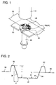
  • Fig. 1 is a typical view showing the state in which a bar code is formed on a spool of an APS film cartridge by the hot stamping.
  • numeral 10 is a hot stamping die
  • numeral 25 is a spool
  • numeral 30 is a resin data disk integrally provided on the one end of the spool
  • numeral 50 is a support member provided on the rear side of the data disk
  • numeral 70 is a transfer material
  • sign HP is a high level pattern transferred onto the data disk
  • numeral 33 is a resin substrate surface on which the data disk surface is exposed as it is (low level pattern LP), and the HP and 33 (LP) constitute the bar code.
  • the support member 50, data disk 30, and the transfer material 70 are superimposed in this order, and the hot stamping die 10 is lowered from the above, and heats and presses, and thermally fuses the transfer material 70 into the shape of the pressing surface of the hot stamping die 10, and transfers it onto the data disk 30.
  • a black HIPS polystyrene resin including rubber
  • its softening point is about 100 °C
  • the transfer material used for the present invention when it is the material which can be sensed by the bar code reading material, it is not specifically limited, however, in the case of the hot stamping for the data disk of the APS film cartridge, the silver material (reflection factor is 70 - 80 %), and the melting temperature is 90 - 100 °C, are preferable.
  • the layer construction in this case the PET film (16 ⁇ m) is a supporting body, and the peeling layer (0.5 ⁇ m), protection layer (1 ⁇ m), aluminum evaporation layer (500 ⁇ ), and acrylic adhesive agent layer (2 - 3 ⁇ m) are superimposed thereon.
  • the hot stamping die heats and presses from the PET film side.
  • the reflection factor can be calculated in such a manner that the ray of light of the wavelength 900 ⁇ 40 nm, is made to be incident upon at the incidence angle of 10 - 20o, the ray of light reflected at the reflection angle of 10 - 20o is measured, and the reflection factor is calculated from a ratio of the amount of the incidence light and the amount of the reflected light.
  • Fig. 2 in which the circumference direction of Fig. 1 is positioned as the horizontal axis, is a sectional view for explaining the shape of the resin substrate after the bar code formation.
  • the transfer material high level pattern which is thermally fused and transferred, is neglected in illustration.
  • the resin substrate is thermally fused by the pressing surface of the hot stamping die, and the portion which is recessed corresponding to the area of the pressing surface, is the concave portion 31.
  • the fused resin stands up on the periphery of the concave portion 31 and forms the bank-like convex portion 32.
  • the surface connecting the concave portion 31 to the convex portion 32 is the tapered portion 34.
  • An angle formed between the concave portion 31 and the tapered portion 34 is ⁇ 3 .
  • an angle formed between the concave portion 31 and the line connecting the top (highest portion) of the convex portion 32 to the edge of the convex portion side of the concave portion 31, is ⁇ 3 .
  • the difference in the height h is the difference in the height between the concave portion 31 (when it is inclined, the lowest position) and the top of the convex portion 32.
  • the distance d is the distance between the top of the convex portion 32 and the edge of the convex portion 32 side of the concave portion 31.
  • the outside of the convex portion is the surface 33 of the resin substrate (low level pattern) which is not affected by the heating and pressing of the hot stamping die.
  • the difference in height k is the difference in height between the concave portion 31 and the resin substrate surface 33.
  • the shape of the bar code formed surface of the resin substrate of the present invention is: the difference in height h is not smaller than 0.01 mm, and not more than 0.05 mm; and the distance d is not larger than 0.1 mm.
  • the reading misconception is decreased, and the transferring can be satisfactorily conducted, and the damage due to the external stress is decreased in the transferred pattern, and problems of the breakage of the transfer material, or the generation of the rag from the transfer material, are suppressed.
  • d 0.
  • angle ⁇ 3 formed between the concave portion 31 and the tapered portion 34 is not more than 135°, the effect of the present invention can be further attained.
  • ⁇ 3 > 90°.
  • Fig. 3 is a typical view for explaining the undulation in the bar code forming portion of the resin substrate before bar code formation.
  • Numeral 30 is the resin material (data disk) before the bar code formation.
  • the bar code forming portion is a portion which is recognized as the bar code by the structure of the high level pattern and the low level pattern, after the transfer material is transferred.
  • the amount of the undulation w is the difference in the height between the highest position P 1 and the lowest position P 2 when the bar code forming portion before the bar code formation is placed on the plane.
  • the bar code forming portion is placed on the rotating stand having the plane surface, the rotating stand is rotated, the height is read by the dial gauge, and the minimum value is subtracted from the maximum value, then, the result is the amount of the undulation w.
  • the difference in the height k between the concave portion 31 and the resin material surface 33 after the bar code formation, described in Fig. 2 is between 1/10 - 1/5 of the amount of the undulation w of the bar code forming portion before the bar code formation, the breakage of the high level pattern, or the generation of the rag is eliminated, and further, the reading misconception can be decreased, thereby, it is preferable.
  • the transferring can be satisfactorily conducted, however, in the case where the amount of the undulation is 50 ⁇ m, when the difference in the height k after the bar code formation is not more than 10 ⁇ m, the reading misconception can be fully decreased, and when the height k is not smaller than 5 ⁇ m, the transferring can be satisfactorily conducted, and the breakage of the pattern or the generation of the rag can be decreased, and the damage due to the external stress can also be decreased.
  • the amount of the undulation w of the bar code forming portion before the bar code formation is not more than 30 ⁇ m, in the same manner, the breakage of the high level pattern or the generation of the rag can be decreased, and the bar code formation with the uniform quality can be attained, and the reading misconception is decreased.
  • the shape of the bar code formed resin substrate surface described in the above Fig. 2 or Fig. 3, can be attained when the resin substrate, hot stamping die, or the pressing condition is made to the optimum conditions. These optimum conditions for attaining the bar code formation will be described below including the description of Fig. 4 - Fig. 5(b).
  • the pressing condition of the hot stamping die is appropriately determined by the relationship between the resin substrate and the transfer material, and in the case of the pressing onto the data disk of the APS film cartridge, when it is determined as following, the shape of the bar code formed resin substrate surface can be attained, and preferable.
  • the cooling time is the time necessary for peeling off the transfer material from the data disk after retreating the hot stamping die from the resin substrate (after the pressing).
  • the above conditions (1) to (4) are applied for the film cartridge in which, specifically, the load bending temperature regulated by JIS K7191 is 100 - 110 °C, when the load is 18.5 kgf/cm 2 .
  • Fig. 4 is a sectional view showing the shape of the leading edge portion of the hot stamping die 10 which can be used for the bar code formation of the present invention.
  • numeral 11 is a heat transfer portion
  • numeral 12 is the leading edge portion
  • numeral 13 is a heat insulating material
  • P is a pressing surface for heating and pressing onto the resin substrate
  • S is a side surface connecting to the pressing surface. The case where an angle formed between the pressing surface P of the hot stamping die and the side surface S is not larger than 90°, is shown.
  • the leading edge of the hot stamping die is generally formed in such a manner that an angle formed between the pressing surface P and the side surface S is 90°, for the easiness of its processing, however, it is an unexpectable effect that, when this angle is not larger than 90°, the shape of the bar code formed resin substrate surface described in above Fig. 2 or Fig. 3 can be easily attained.
  • the angle formed between the pressing surface P and the side surface S is not more than 85°.
  • the leading edge portion 12 of the hot stamping die 10 is detachably attached onto the lower side of the heat transfer portion 11.
  • the leading edge portion 12 is structured by the pressing surface P and the side surface S, and by heating and pressing the pressing surface P onto the transfer material, the transferring of the bar code onto the data disk is conducted.
  • the known heat transfer means can be used, however, in the case of the stamping onto the data disk of the APS film cartridge, it is preferable that a cartridge heater of 500 W is arranged in the heat transfer portion 11 as a main heater, and further, the cartridge heater of 70 W is arranged near the trailing edge portion 12 of the hot stamping die in the heat transfer portion 11 as an auxiliary heater.
  • the material in which the glass fiber is hardened by the non-organic bond, or the material in which noncombustible heat insulation laminated plate is adhered onto the periphery by the thickness of about 10 mm is listed.
  • thermocouple platinum resistor
  • the metal or ceramic normally used for the hot stamping can be used, however, the steel such as SKD is preferable.
  • the angle ⁇ 1 of the leading edge portion 12 can be formed by the normal processing method such as the electric discharge machining, or polishing processing.
  • an air cylinder, or mechanical press can be used for the drive of vertical movement of the hot stamping die when the hot stamping die is pressed.
  • an air cylinder, or mechanical press can be used.
  • the pressing surface P and the receiving surface of the support member 50 are located almost in parallel, and at this time, it is preferable that the deviation from the parallelism of the pressing surface P with the resin substrate is within 30 ⁇ m.
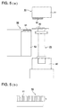
  • Figs. 5(a) and 5(b) are typical views for explaining the case where the elastic member is provided on the supporting member 50, in the bar code forming method of the present invention.
  • the shape of the bar cord formed resin substrate surface described in above Fig. 2 or Fig. 3 can be easily attained, which is a new discovery.
  • Fig. 5(a) is a side view of the bar code forming apparatus
  • Fig. 5(b) is a partial enlargement view of the supporting member of the bar code forming apparatus.
  • numeral 10 is a hot stamping die
  • numeral 25 is a spool
  • numeral 30 is a disk
  • numeral 60 is a spool holder
  • numeral 50 is a supporting member to support the data disk from the reverse side (rear side) to the hot stamping die 10.
  • the spool 25 is fixed by the spool holder 60 under the condition that the data disk 30 on which the bar code is formed, is located in the upper portion.
  • the supporting member 50 is moved from the left side in the drawing and inserted into the rear side of the bar code forming portion (left side in the drawing) of the data disk 30.
  • the supporting member 50 supports the data disk 30 which is heated and pressed, by the hot stamping die 10 through the transfer material (not shown), so that the bar code forming portion of the data disk 30 is efficiently pressed by the pressing force.
  • the elastic member 51 is adhered onto the side which is in contact with the data disk 30, of the supporting member 50, and the more uniform pressing force can be loaded onto the bar code forming portion of the data disk 30, as compared to the case where the elastic member is not provided, and thereby, the problem of the breakage of the high level pattern or the generation of the rag can be prevented. Thereby, the shape of the bar code formed resin substrate surface as described in above Fig. 2 or Fig. 3 can be attained and the misconception can be decreased.
  • the elastic member 51 is the material having the elasticity, it is not specifically limited, but rubber is preferable, and its hardness is 80 degrees - 100 degrees is more preferable. In the rubber materials, the urethane rubber of rubber hardness of 90 degrees - 100 degrees is most preferable.
  • the supporting member 50 is reinforced with the rib 52, except the portion inserted into the lower side of the data disk 30, so that the supporting member 50 is not bent even when being loaded by the hot stamping die.
  • d, h, k, amount of the undulation, ⁇ 1 and ⁇ 3 are satisfied in the direction in which the reading apparatus is relatively moved to the bar code, at least at the time of bar code reading, these are allowable, and it is specifically preferable that these are satisfied also in the direction perpendicular the above direction.
  • Samples 1 - 8 in which the bar code forming apparatus by the hot stamping is used, and the angle formed between the pressing surface P of the leading edge of the hot stamping die and the side surface S, and the existence of the elastic material of the supporting member, and the temperature of the leading edge portion of the hot stamping die, are changed as shown in Table 1, and except those, the bar code is formed under the following conditions, are made.
  • the difference in height k between the concave portion and the resin substrate surface which is not affected by the heating of the hot stamping die is within the range of 0.01 - 0.05 mm for all samples.
  • the data disk of the APS film cartridge Made of black HIPS (polystyrene resin including rubber).
  • the softening point is 100 °C.
  • the laminated film which is silver material, whose reflection factor of 70 - 80 %, and the melting temperature is 95 °C.
  • the layer structure is as follows: from the pressing surface side of the hot stamping die, the PET film (16 ⁇ m)/ peeling layer (0.5 ⁇ m)/ protective layer (1 ⁇ m)/aluminum evaporation layer (500 ⁇ )/ acrylic adhesive agent layer (2 - 3 ⁇ m).
  • the hot stamping die shown in Fig. 4 and Figs. 5(a) and 5(b) is used.
  • the leading edge portion is made of SKD steel.
  • the heat insulation material in which glass fibers are hardened by the non-organic bond into the sheet-like, is adhered on the periphery of the heat transfer portion. Further, a thermocouple (platinum resistor) is provided near the leading edge portion, and the measurement value of the temperature is fed back to both heaters, and the temperature is adjusted.
  • the urethane rubber of the rubber hardness 95 is used, and its thickness t is 1 mm. Further, the supporting member is adjusted so that the deviation of the pressing surface of the hot stamping die and resin substrate from the parallelism is within 30 ⁇ m.
  • the samples of the present invention are excellent for the prevention of both the reading misconception and the breakage of the transfer material.
  • the present invention can provide the bar code forming method to form the bar code having the quality in which the bar code reading sensor does not cause the reading misconception, and the APS film cartridge on which the bar code in which the bar code reading sensor does not cause the reading misconception, is formed.

Landscapes

  • Physics & Mathematics (AREA)
  • General Physics & Mathematics (AREA)
  • Engineering & Computer Science (AREA)
  • Theoretical Computer Science (AREA)
  • Casting Or Compression Moulding Of Plastics Or The Like (AREA)
  • Shaping Of Tube Ends By Bending Or Straightening (AREA)
  • Duplication Or Marking (AREA)
  • Liquid Crystal (AREA)

Abstract

A bar code forming method, which has the step of: forming the bar code which satisfies the following conditions, by transferring at least one portion of the transfer material onto the resin substrate by heating and pressing the transfer material onto the resin substrate, wherein, when the difference of the height between the concave portion formed on the resin substrate by the heating and pressing, and the convex portion protruding on the periphery of the concave portion, is h, and the distance between the top of the convex portion and the edge of the convex portion side of the concave portion, is d, <DF>0.01 mm ≤ h ≤ 0.05 mm, and d < 1 mm. </DF> <IMAGE>

Description

BACKGROUND OF THE INVENTION
The present invention relates to a bar code forming method by which the bar code is formed on a resin substrate by a hot stamping die, and to an APS film cartridge on which a bar code is formed.
In a photographic film cartridge according to the standard of the advanced photo system (hereinafter, called APS film cartridge), the photographic film is wound around a resin spool, and covered by a resin film magazine. On one end of this spool, a data disk as the resin substrate integrally provided with the spool is provided, and the bar code displaying the film data such as the film sensitivity and the number of exposures, is recorded. This bar code can be formed by various methods, and for example, in Japanese Tokkaihei No. 8-254794, a method by which a low level pattern using the data disk surface (black) as it is, and a high level pattern in which the member having the large reflection factor (a transfer material such as the transfer foil) is thermally transferred on the disk surface, are structured and provided, is disclosed. This is a method by which the bar code is provided by so-called hot stamping.
In the hot stamping by which the bar code is formed on the resin substrate, transferring is conducted, at the time of heating and pressing, in such a manner that the resin data disk surface is slightly melted, and the transfer foil as the transfer material is stuck in the data disk. A sectional view of the conventional bar code forming portion of the data disk by the hot stamping after transferring is as shown in Fig. 6. A portion which is heated and pressed by the hot stamping, is a concave portion 31, and the outside of the concave portion is formed into a convex portion 32 by the melt resin. The inclined surface connecting the concave portion 31 and the convex portion 32 is a tapered portion 34. Further outside the convex portion 32 is the resin substrate surface 33 of the original data disk which is not affected by the heating and pressing by the hot stamping, and this is the low level pattern LP. The periphery of the concave portion 31 is rimmed by the resin convex portion 32 into the shape of just a plate of the hot stamping.
On the bar code forming surface which is formed by such the hot stamping, and has the concave portion 31 and convex portion 32 as shown in Fig. 6, it is found that, depending on the shape of the concave portion 31 and the convex portion 32, or the condition of formation of the bar code, the misconception of the bar code reading sensor easily occurs. Specifically, in the APS camera whose sensor has the high sensitivity, it is found that this tendency is more conspicuous.
SUMMARY OF THE INVENTION
The object of the present invention is, in the bar code forming method in which the transfer material is heated and pressed by the hot stamping die and the bar code is formed on the resin substrate by the transferring, to provide a bar code forming method to form the bar code having the quality by which the bar code reading sensor does not cause the misconception of the reading, and to provide an APS film cartridge on which the bar code by which the bar code reading sensor does not cause the misconception of the reading, is formed.
The above described object of the invention can be attained by one of the following structures (1) - (19).
  • (1) A bar code forming method, which has the step of: forming the bar code which satisfies the following conditions, by transferring at least one portion of the transfer material onto the resin substrate by heating and pressing the transfer material onto the resin substrate, wherein, when the difference of the height between the concave portion formed on the resin substrate by the heating and pressing, and the convex portion protruding on the periphery of the concave portion, is h, and the distance between the top of the convex portion and the edge of the convex portion side of the concave portion, is d, 0.01 mm ≤ h ≤ 0.05 mm, and d < 1 mm.
  • (2) In the method of the structure (1), the step for forming the bar code is conducted by heating and pressing the transfer material by the hot stamping die.
  • (3) In the method of the structure (2), the angle 3 formed between the concave portion, and the tapered portion connecting the concave portion to the convex portion, is not more than 135°.
  • (4) In the method of the structure (2) or (3), the angle 1 formed between the pressing surface of the hot stamping die by which the resin substrate is heated and pressed through the transfer material, and the side surface connected to the pressing surface, is not larger than 90°.
  • (5) In the methods of the structures (2) to (4), a supporting member is provided on the rear side of the surface of the resin substrate on which the bar code is formed, and an elastic body is provided on the surface which is in contact with the resin substrate, of the supporting member.
  • (6) In the method of the structure (5), the elastic body is rubber, and the thickness of the rubber is 0.5 - 2 mm, and the rubber hardness is 70 degrees - 100 degrees.
  • (7) In the method of the structure (2), the difference of the height k between the concave portion, and the resin substrate surface which is not affected by the heat by the heating and pressing, is not smaller than 1/10 times and not more than 1/5 times of the amount of undulation in the bar code forming portion of the resin substrate.
  • (8) In the methods of the structures (2) to (7), the amount of the undulation in the bar code forming portion of the resin substrate is not more than 30 µm.
  • (9) In the methods of the structures (2) to (8), by setting the temperature of the leading edge portion contacting with the resin substrate of the hot stamping die to 120 °C - 180 °C, and the time of the heating and pressing to not longer than 0.4 sec, the difference of the height is made to not smaller than 0.01 mm, and not more than 0.05 mm.
  • (10) In the methods of the structures (2) to (9), the surrounding of the heat transfer portion of the hot stamping die is covered by the heat insulating material.
  • (11) In the methods of the structures (2) to (10), the resin substrate is the data disk of the APS film cartridge.
  • (12) In the method of the structure (1), d > 0.
  • (13) The bar code forming method, which having the following step: a step in which the bar code is formed in such a manner that at least one portion of the transfer material is transferred onto the resin substrate, by heating and pressing the transfer material onto the resin substrate by the hot stamping die so that the following conditions are satisfied, wherein, when the temperature of the leading edge portion of the hot stamping die is T, the pressing force by the hot stamping die is F, and the pressing time of the hot stamping die is t, 120 °C ≤ T ≤ 180 °C, 100 kgf ≤ F ≤ 400 kgf, and 0.2 ≤ t ≤ 0.4 .
  • (14) In the method of the structure (13), when the cooling time is S, the heating and pressing is carried out so that the condition of 0.2 sec ≤ S ≤ 0.4 sec is satisfied.
  • (15) In the method of the structure (13), the load deflection temperature of the resin substrate is 100 - 110 °C when the load is 18. 5 kgf/cm2.
  • (16) In the method of the structure (13), the resin substrate is the data disk of the APS film cartridge.
  • (17) In the film cartridge, a spool around which the film is wound, and the data disk which is arranged on the spool, and has the resin substrate in at least one portion, wherein the data disk has the bar code formed by heating and pressing the transfer material, and the bar code portion satisfies the following conditions: when the difference of the height between the concave portion formed on the resin substrate by the heating and pressing, and the convex portion protruding on the periphery of the concave portion, is h, and the distance between the top of the convex portion and the edge of the convex portion side of the concave portion, is d, 0.01 mm ≤ h ≤ 0.05 mm and d < 1 mm.
  • (18) In the film cartridge of the structure (17), the film cartridge is the APS film cartridge.
  • (19) In the film cartridge of the structure (17), the bar code portion is formed by the hot stamping die.
  • Further, the preferred structures 1 - 11 are as follows.
  • 1. A bar code forming method, in which the transfer material is heated and pressed, and the bar code is formed onto the resin substrate by transferring by the hot stamping die, the bar code forming method is characterized in that: after the formation of the bar code, the difference of the height h between the concave portion formed on the resin substrate by the heating and pressing by the hot stamping die, and the convex portion protruding on the periphery of the concave portion, is not smaller than 0.01 mm, and not more than 0.05 mm, and the distance d between the top of the convex portion and the edge of the convex portion side of the concave portion, is not larger than 0.1 mm.
  • 2. The bar code forming method according to the method 1, wherein the angle 3 formed between the concave portion, and the tapered portion connecting the concave portion to the convex portion, is not more than 135°.
  • 3. The bar code forming method according to the method 1 or 2, wherein the angle 1 formed between the pressing surface of the hot stamping die to heat and press onto the resin substrate through the transfer material, and the side surface connecting to the pressing surface, is not larger than 90°.
  • 4. The bar code forming method according to any one of the methods 1 - 3, wherein a supporting member is provided on the rear side of the surface of the resin substrate on which the bar code is formed, and an elastic body is provided on the surface of the resin substrate with which the supporting member comes into contact.
  • 5. The bar code forming method according to the method 4, wherein the elastic body is rubber, and the thickness of the rubber is 0.5 - 2 mm, and the rubber hardness is 70 degrees to 100 degrees.
  • 6. The bar code forming method according to any one of the methods 1 - 5, wherein the difference of the height k between the concave portion, and the surface of the resin substrate which is not affected by the heating of the hot stamping die, is 1/5 to 1/10 of the amount of the undulation in the bar code forming portion of the resin substrate.
  • 7. The bar code forming method according to any one of the methods 1 - 6, wherein the amount of the undulation in the bar code forming portion of the resin substrate is not larger than 30 µm.
  • 8. The bar code forming method according to any one of the methods 1 - 7, wherein, when the temperature of the leading edge portion which is in contact with the resin substrate of the hot stamping die is 120 °C - 180 °C, and the heating and pressing time is not more than 0.4 sec, then, the difference of the height h is not smaller than 0.01 mm, and not more than 0.05 mm.
  • 9. The bar code forming method according to any one of the methods 1 - 8, wherein the surrounding of the heat transfer portion of the hot stamping die is covered by the heat insulating material.
  • 10. The bar code forming method according to any one of the methods 1 - 9, wherein the resin substrate is the data disk of the APS film cartridge.
  • 11. The APS film cartridge having the bar code formed by heating and pressing the transfer material by the hot stamping die, the APS film cartridge is characterized in that: after the formation of the bar code, the difference of the height h between the concave portion formed on the resin substrate by the heating and pressing by the hot stamping die, and the convex portion protruding on the periphery of the concave portion, is not smaller than 0.01 mm, and not more than 0.05 mm, and the distance between the edge of the concave portion side of the convex portion and the edge of the convex portion side of the concave portion, is not larger than 0.1 mm.
  • BRIEF DESCRIPTION OF THE DRAWINGS
  • Fig. 1 is a typical view showing the state in which a bar code is formed on a spool of an APS film cartridge by the hot stamping die.
  • Fig. 2 is a sectional view showing the shape of the leading edge portion of a hot stamping die which can be used for the bar code forming method of the present invention.
  • Fig. 3 is a typical view for explaining the case where an elastic member is provided on a support member of the bar code forming apparatus in the bar code forming method of the present invention.
  • Fig. 4 is a sectional view for explaining the shape a resin substrate after the bar code formation.
  • Figs. 5(a), and 5(b) are typical views for explaining an undulation in the bar code forming portion of the resin substrate before the bar code formation.
  • Fig. 6 is a sectional view of the bar code forming portion of the conventional data disk after transferring
  • DETAILED DESCRIPTION OF THE PREFERRED EMBODIMENT
    Referring to the drawings, the embodiment of the present invention will be described below, however, the present invention is not limited to that.
    Fig. 1 is a typical view showing the state in which a bar code is formed on a spool of an APS film cartridge by the hot stamping. In the drawing, numeral 10 is a hot stamping die, numeral 25 is a spool, numeral 30 is a resin data disk integrally provided on the one end of the spool, numeral 50 is a support member provided on the rear side of the data disk, numeral 70 is a transfer material, sign HP is a high level pattern transferred onto the data disk, numeral 33 is a resin substrate surface on which the data disk surface is exposed as it is (low level pattern LP), and the HP and 33 (LP) constitute the bar code. From the lower side of the drawing, the support member 50, data disk 30, and the transfer material 70 are superimposed in this order, and the hot stamping die 10 is lowered from the above, and heats and presses, and thermally fuses the transfer material 70 into the shape of the pressing surface of the hot stamping die 10, and transfers it onto the data disk 30.
    As the resin substrate used in the present invention, specifically not limited, but, in the case of the data disk of the APS film cartridge, a black HIPS (polystyrene resin including rubber), and its softening point is about 100 °C, are preferable.
    As the transfer material used for the present invention, when it is the material which can be sensed by the bar code reading material, it is not specifically limited, however, in the case of the hot stamping for the data disk of the APS film cartridge, the silver material (reflection factor is 70 - 80 %), and the melting temperature is 90 - 100 °C, are preferable. As the layer construction in this case, the PET film (16 µm) is a supporting body, and the peeling layer (0.5 µm), protection layer (1 µm), aluminum evaporation layer (500 Å), and acrylic adhesive agent layer (2 - 3 µm) are superimposed thereon. For this transfer material, the hot stamping die heats and presses from the PET film side. Incidentally, the reflection factor can be calculated in such a manner that the ray of light of the wavelength 900 ± 40 nm, is made to be incident upon at the incidence angle of 10 - 20º, the ray of light reflected at the reflection angle of 10 - 20º is measured, and the reflection factor is calculated from a ratio of the amount of the incidence light and the amount of the reflected light.
    Fig. 2 in which the circumference direction of Fig. 1 is positioned as the horizontal axis, is a sectional view for explaining the shape of the resin substrate after the bar code formation. In Fig. 2, the transfer material (high level pattern) which is thermally fused and transferred, is neglected in illustration. The resin substrate is thermally fused by the pressing surface of the hot stamping die, and the portion which is recessed corresponding to the area of the pressing surface, is the concave portion 31. The fused resin stands up on the periphery of the concave portion 31 and forms the bank-like convex portion 32. The surface connecting the concave portion 31 to the convex portion 32 is the tapered portion 34. An angle formed between the concave portion 31 and the tapered portion 34 is 3. When the tapered portion 34 draws the curved line, an angle formed between the concave portion 31 and the line connecting the top (highest portion) of the convex portion 32 to the edge of the convex portion side of the concave portion 31, is 3. The difference in the height h is the difference in the height between the concave portion 31 (when it is inclined, the lowest position) and the top of the convex portion 32. Further, the distance d is the distance between the top of the convex portion 32 and the edge of the convex portion 32 side of the concave portion 31. The outside of the convex portion is the surface 33 of the resin substrate (low level pattern) which is not affected by the heating and pressing of the hot stamping die. Further, the difference in height k is the difference in height between the concave portion 31 and the resin substrate surface 33.
    The shape of the bar code formed surface of the resin substrate of the present invention is: the difference in height h is not smaller than 0.01 mm, and not more than 0.05 mm; and the distance d is not larger than 0.1 mm. By satisfying this shape, the reading misconception is decreased, and the transferring can be satisfactorily conducted, and the damage due to the external stress is decreased in the transferred pattern, and problems of the breakage of the transfer material, or the generation of the rag from the transfer material, are suppressed. Preferably, d > 0.
    Further, when the angle 3 formed between the concave portion 31 and the tapered portion 34 is not more than 135°, the effect of the present invention can be further attained. Preferably, 3 > 90°.
    Fig. 3 is a typical view for explaining the undulation in the bar code forming portion of the resin substrate before bar code formation. Numeral 30 is the resin material (data disk) before the bar code formation. The bar code forming portion is a portion which is recognized as the bar code by the structure of the high level pattern and the low level pattern, after the transfer material is transferred. The irregularity of the thickness of the resin substrate when the resin substrate of the bar code forming portion before the bar code formation, is viewed horizontally, is the undulation. The amount of the undulation w is the difference in the height between the highest position P1 and the lowest position P2 when the bar code forming portion before the bar code formation is placed on the plane. As the measuring method, the bar code forming portion is placed on the rotating stand having the plane surface, the rotating stand is rotated, the height is read by the dial gauge, and the minimum value is subtracted from the maximum value, then, the result is the amount of the undulation w. When the difference in the height k between the concave portion 31 and the resin material surface 33 after the bar code formation, described in Fig. 2, is between 1/10 - 1/5 of the amount of the undulation w of the bar code forming portion before the bar code formation, the breakage of the high level pattern, or the generation of the rag is eliminated, and further, the reading misconception can be decreased, thereby, it is preferable. For example, in the case where the amount of the undulation of the whole range of the barcode forming portion before the bar code formation, is 50 - 60 µm, when the difference in the height k after the bar code formation is not smaller than 10 µm, the transferring can be satisfactorily conducted, however, in the case where the amount of the undulation is 50 µm, when the difference in the height k after the bar code formation is not more than 10 µm, the reading misconception can be fully decreased, and when the height k is not smaller than 5 µm, the transferring can be satisfactorily conducted, and the breakage of the pattern or the generation of the rag can be decreased, and the damage due to the external stress can also be decreased.
    Further, when the amount of the undulation w of the bar code forming portion before the bar code formation is not more than 30 µm, in the same manner, the breakage of the high level pattern or the generation of the rag can be decreased, and the bar code formation with the uniform quality can be attained, and the reading misconception is decreased.
    The shape of the bar code formed resin substrate surface described in the above Fig. 2 or Fig. 3, can be attained when the resin substrate, hot stamping die, or the pressing condition is made to the optimum conditions. These optimum conditions for attaining the bar code formation will be described below including the description of Fig. 4 - Fig. 5(b).
    The pressing condition of the hot stamping die is appropriately determined by the relationship between the resin substrate and the transfer material, and in the case of the pressing onto the data disk of the APS film cartridge, when it is determined as following, the shape of the bar code formed resin substrate surface can be attained, and preferable.
  • (1) The temperature of the leading edge portion: 120 °C - 180 °C, (preferably, 140 °C - 170 °C, and more preferably, 155 °C - 160 °C)
  • (2) The pressing force: 100 - 400 kgf (preferably, 220 kgf: the pressing by the air cylinder, etc.)
  • (3) The pressing time: 0.2 - 0.4 sec (preferably, 0.2 - 0.3 sec)
  • (4) The cooling time: 0.2 - 0.4 sec (preferably, 0.2 - 0.3 sec)
  • Incidentally, the cooling time is the time necessary for peeling off the transfer material from the data disk after retreating the hot stamping die from the resin substrate (after the pressing).
    Incidentally, it is preferable that the above conditions (1) to (4) are applied for the film cartridge in which, specifically, the load bending temperature regulated by JIS K7191 is 100 - 110 °C, when the load is 18.5 kgf/cm2.
    Fig. 4 is a sectional view showing the shape of the leading edge portion of the hot stamping die 10 which can be used for the bar code formation of the present invention. In the drawing, numeral 11 is a heat transfer portion, numeral 12 is the leading edge portion, numeral 13 is a heat insulating material, P is a pressing surface for heating and pressing onto the resin substrate, and S is a side surface connecting to the pressing surface. The case where an angle formed between the pressing surface P of the hot stamping die and the side surface S is not larger than 90°, is shown. Normally, the leading edge of the hot stamping die is generally formed in such a manner that an angle formed between the pressing surface P and the side surface S is 90°, for the easiness of its processing, however, it is an unexpectable effect that, when this angle is not larger than 90°, the shape of the bar code formed resin substrate surface described in above Fig. 2 or Fig. 3 can be easily attained. Preferably, the angle formed between the pressing surface P and the side surface S is not more than 85°.
    The leading edge portion 12 of the hot stamping die 10 is detachably attached onto the lower side of the heat transfer portion 11. The leading edge portion 12 is structured by the pressing surface P and the side surface S, and by heating and pressing the pressing surface P onto the transfer material, the transferring of the bar code onto the data disk is conducted.
    Also for the heat transfer portion 11 of the hot stamping die used for the present invention, the known heat transfer means can be used, however, in the case of the stamping onto the data disk of the APS film cartridge, it is preferable that a cartridge heater of 500 W is arranged in the heat transfer portion 11 as a main heater, and further, the cartridge heater of 70 W is arranged near the trailing edge portion 12 of the hot stamping die in the heat transfer portion 11 as an auxiliary heater.
    As the heat insulation material 13, the material in which the glass fiber is hardened by the non-organic bond, or the material in which noncombustible heat insulation laminated plate is adhered onto the periphery by the thickness of about 10 mm, is listed. A method by which the heat insulating material is provided on the periphery of the heat transfer portion, is conducted by winding the sheet-like insulation member around the heat transfer portion.
    It is preferable that a thermocouple (platinum resistor) is provided near the trailing edge portion 12, and the measurement value of the temperature is fed back to both heaters, and the temperature is adjusted.
    AS the material of the leading edge portion 12, the metal or ceramic normally used for the hot stamping can be used, however, the steel such as SKD is preferable. Further, the angle 1 of the leading edge portion 12 can be formed by the normal processing method such as the electric discharge machining, or polishing processing.
    For the drive of vertical movement of the hot stamping die when the hot stamping die is pressed, an air cylinder, or mechanical press can be used. At the time of pressing, it is necessary that the pressing surface P and the receiving surface of the support member 50 are located almost in parallel, and at this time, it is preferable that the deviation from the parallelism of the pressing surface P with the resin substrate is within 30 µm.
    Figs. 5(a) and 5(b) are typical views for explaining the case where the elastic member is provided on the supporting member 50, in the bar code forming method of the present invention. When the elastic member is attached to the supporting member, the shape of the bar cord formed resin substrate surface described in above Fig. 2 or Fig. 3 can be easily attained, which is a new discovery.
    Fig. 5(a) is a side view of the bar code forming apparatus, and Fig. 5(b) is a partial enlargement view of the supporting member of the bar code forming apparatus. In the drawing, numeral 10 is a hot stamping die, numeral 25 is a spool, numeral 30 is a disk, numeral 60 is a spool holder, and numeral 50 is a supporting member to support the data disk from the reverse side (rear side) to the hot stamping die 10. In Fig. 5(a), the spool 25 is fixed by the spool holder 60 under the condition that the data disk 30 on which the bar code is formed, is located in the upper portion. The supporting member 50 is moved from the left side in the drawing and inserted into the rear side of the bar code forming portion (left side in the drawing) of the data disk 30. The supporting member 50 supports the data disk 30 which is heated and pressed, by the hot stamping die 10 through the transfer material (not shown), so that the bar code forming portion of the data disk 30 is efficiently pressed by the pressing force. The elastic member 51 is adhered onto the side which is in contact with the data disk 30, of the supporting member 50, and the more uniform pressing force can be loaded onto the bar code forming portion of the data disk 30, as compared to the case where the elastic member is not provided, and thereby, the problem of the breakage of the high level pattern or the generation of the rag can be prevented. Thereby, the shape of the bar code formed resin substrate surface as described in above Fig. 2 or Fig. 3 can be attained and the misconception can be decreased.
    When the thickness t shown in Fig. 5(b) of the elastic member 51 is 0.5 - 1 mm, the more effect can be attained. When the elastic member 51 is the material having the elasticity, it is not specifically limited, but rubber is preferable, and its hardness is 80 degrees - 100 degrees is more preferable. In the rubber materials, the urethane rubber of rubber hardness of 90 degrees - 100 degrees is most preferable.
    Further, it is preferable that the supporting member 50 is reinforced with the rib 52, except the portion inserted into the lower side of the data disk 30, so that the supporting member 50 is not bent even when being loaded by the hot stamping die. Incidentally, when the above described d, h, k, amount of the undulation, 1 and 3, are satisfied in the direction in which the reading apparatus is relatively moved to the bar code, at least at the time of bar code reading, these are allowable, and it is specifically preferable that these are satisfied also in the direction perpendicular the above direction.
    (Example 1)
    Samples 1 - 8 in which the bar code forming apparatus by the hot stamping is used, and the angle formed between the pressing surface P of the leading edge of the hot stamping die and the side surface S, and the existence of the elastic material of the supporting member, and the temperature of the leading edge portion of the hot stamping die, are changed as shown in Table 1, and except those, the bar code is formed under the following conditions, are made. In respective samples, the difference in height h between the concave portion on the resin substrate after the bar code formation, and convex portion protruding on the periphery of the concave portion; the distance d between the top of the convex portion, and the edge of the convex portion side of the concave portion; angle 3 formed between the concave portion, and the taper portion connecting the concave portion to the convex portion; and the results in which the effects by those are estimated by the following estimation method, are collectively shown in Table 1.
    Incidentally, the difference in height k between the concave portion and the resin substrate surface which is not affected by the heating of the hot stamping die, is within the range of 0.01 - 0.05 mm for all samples.
    (Resin substrate)
    The data disk of the APS film cartridge. Made of black HIPS (polystyrene resin including rubber). The softening point is 100 °C.
    (Transfer material)
    The laminated film which is silver material, whose reflection factor of 70 - 80 %, and the melting temperature is 95 °C. The layer structure is as follows: from the pressing surface side of the hot stamping die, the PET film (16 µm)/ peeling layer (0.5 µm)/ protective layer (1 µm)/aluminum evaporation layer (500 Å)/ acrylic adhesive agent layer (2 - 3 µm).
    (Hot stamping die)
    The hot stamping die shown in Fig. 4 and Figs. 5(a) and 5(b) is used. The leading edge portion is made of SKD steel.
    An angle 1 formed between the pressing surface P of the leading edge portion and the side surface S: 80° - 85° (Table 1). The heat transfer portion: A 500 W cartridge heater is arranged as a main heater on the reverse side to the pressing surface P of the leading edge portion, and further, a 70 W cartridge heater is arranged as an auxiliary heater near the leading edge of the hot stamping die. The heat insulation material in which glass fibers are hardened by the non-organic bond into the sheet-like, is adhered on the periphery of the heat transfer portion. Further, a thermocouple (platinum resistor) is provided near the leading edge portion, and the measurement value of the temperature is fed back to both heaters, and the temperature is adjusted.
    (Supporting member)
    When the elastic member is used, the urethane rubber of the rubber hardness 95 is used, and its thickness t is 1 mm. Further, the supporting member is adjusted so that the deviation of the pressing surface of the hot stamping die and resin substrate from the parallelism is within 30 µm.
    (The pressing conditions of the hot stamping die)
    The temperature of the leading edge portion: 110 - 185 °C (Table 1), the pressing force: 220 kgf, the pressing time: 0.3 sec., the cooling time: 0.3 sec.
    (Estimation method)
    Relating to the reading misconception, a bar code reading measuring device in which a camera with low signal output is used as a base, is made, and referring to the level of the signal output, the reading misconception is judged by the right or wrong of the reading. Further, relating to the transferability, the existence of the breakage of the transfer is visually estimated.
    Angle of leading edge portion 1 Temperature of leading edge portion (°C) Existence of elastic member Difference in height h (mm) Distance d (mm) Angle 3 Reading misconception Transferability Note
    Sample
    1 80° 155 yes 0.05 0.01 100° P. I
    Sample 2 80° 185 yes 0.11 0.06 110° C. E
    Sample 3 90° 155 yes 0.05 0.05 135° P. I
    Sample 4 90° 155 no 0.07 0.05 130° C. E
    Sample 5 90° 185 yes 0.11 0.13 140° X C. E
    Sample 6 90° 185 no 0.13 0.13 138° X C. E
    Sample 7 90° 110 yes 0.005 0.002 120° C. E
    Sample 8 90° 110 no 0.004 0.002 125° X X C. E
    It can be seen that the samples of the present invention are excellent for the prevention of both the reading misconception and the breakage of the transfer material.
    In the bar code forming method in which the transfer material is heated and pressed by the hot stamping die, and bar code is formed by the transferring, the present invention can provide the bar code forming method to form the bar code having the quality in which the bar code reading sensor does not cause the reading misconception, and the APS film cartridge on which the bar code in which the bar code reading sensor does not cause the reading misconception, is formed.

    Claims (19)

    1. A bar code forming method, comprising the steps of:
      heating and pressing a transfer material onto a resin substrate, thereby transferring at least one portion of the transfer material onto the resin substrate so that a bar code is formed, wherein the bar code satisfies the following conditions: 0.01 mm ≤ h ≤ 0.05 mm, and d < 1 mm where h represents a difference of a height between a concave portion formed on the resin substrate by heating and pressing, and a convex portion protruding on a periphery of the concave portion, and d represents a distance between a top of the convex portion and an edge of a convex portion side of the concave portion.
    2. The bar code forming method of claim 1, wherein the step of the heating and pressing the transfer material is conducted by a hot stamping die.
    3. The bar code forming method of claim 2, wherein an angle 3 formed between the concave portion and a tapered portion connecting the concave portion to the convex portion, is not more than 135°.
    4. The bar code forming method of claim 2, wherein an angle 1 formed between the pressing surface of the hot stamping die by which the resin substrate is heated and pressed through the transfer material, and a side surface connected to the pressing surface, is not larger than 90°.
    5. The bar code forming method of claim 2, wherein further comprising the step of:
      providing a supporting member on a rear side of the surface of the resin substrate on which the bar code is formed, and an elastic body on a surface which is in contact with the resin substrate, of the supporting member.
    6. The bar code forming method of claim 5, wherein the elastic body is rubber, and a thickness of the rubber is 0.5 - 2 mm, and a rubber hardness is 70 degrees - 100 degrees.
    7. The bar code forming method of claim 2, wherein a difference of a height k between the concave portion, and the resin substrate surface which is not affected by the heat by the heating and pressing, is not smaller than 1/10 times and not more than 1/5 times of the amount of undulation in the bar code forming portion of the resin substrate.
    8. The bar code forming method of claim 2, wherein an amount of the undulation in a bar code forming portion of the resin substrate is not more than 30 µm.
    9. The bar code forming method of claim 2, wherein by setting the temperature of a leading edge portion contacting with the resin substrate of the hot stamping die to 120 °C - 180 °C, and the time of the heating and pressing to not longer than 0.4 sec, the difference of the height is made to not less than 0.01 mm, and not more than 0.05 mm.
    10. The bar code forming method of claim 2, wherein a surrounding of the heat transfer portion of the hot stamping die is covered by a heat insulating material.
    11. The bar code forming method of claim 2, wherein the resin substrate is a data disk of the APS film cartridge.
    12. The bar code forming method of claim 1, wherein the following condition is satisfied: d > 0.
    13. A bar code forming method, comprising the steps of:
      heating and pressing a transfer material onto a resin substrate by a hot stamping die, thereby transferring at least one portion of the transfer material onto the resin substrate so that a bar code is formed, wherein the following conditions are satisfied: 120 °C ≤ T ≤ 180 °C, 100 kgf ≤ F ≤ 400 kgf, and 0.2 ≤ t ≤ 0.4 where T represents temperature of a leading edge portion of the hot stamping die, F represents a pressing force by the hot stamping die, and t represents a pressing time of the hot stamping die.
    14. The bar code forming method of claim 13, wherein the heating and pressing is carried out so that the condition of 0.2 sec ≤ S ≤ 0.4 sec is satisfied where S represents a cooling time.
    15. The bar code forming method of claim 13, wherein load deflection temperature of the resin substrate is 100 - 110 °C when a load is 18. 5 kgf/cm2.
    16. The bar code forming method of claim 13, wherein the resin substrate is a data disk of an APS film cartridge.
    17. A film cartridge comprising:
      (a) a spool around which a film is wound; and
      (b) a data disk which is arranged on the spool, having a resin substrate in at least one portion thereof, wherein the data disk has a bar code portion formed by heating and pressing a transfer material, and the bar code portion satisfies the following conditions: 0.01 mm ≤ h ≤ 0.05 mm and d < 1 mm where h represents a difference of a height between a concave portion formed on the resin substrate by heating and pressing, and a convex portion protruding on a periphery of the concave portion, and d represents a distance between a top of the convex portion and an edge of a convex portion side of the concave portion.
    18. The film cartridge of claim 17, wherein the film cartridge is an APS film cartridge.
    19. The film cartridge of claim 17, wherein the bar code portion is formed by a hot stamping die.
    EP00307867A 1999-09-16 2000-09-12 Bar code forming method and APS film cartridge having bar code thereon Withdrawn EP1085450A3 (en)

    Applications Claiming Priority (2)

    Application Number Priority Date Filing Date Title
    JP26198899A JP2001083665A (en) 1999-09-16 1999-09-16 Bar code forming method and aps film cartridge
    JP26198899 1999-09-16

    Publications (2)

    Publication Number Publication Date
    EP1085450A2 true EP1085450A2 (en) 2001-03-21
    EP1085450A3 EP1085450A3 (en) 2003-01-08

    Family

    ID=17369454

    Family Applications (1)

    Application Number Title Priority Date Filing Date
    EP00307867A Withdrawn EP1085450A3 (en) 1999-09-16 2000-09-12 Bar code forming method and APS film cartridge having bar code thereon

    Country Status (3)

    Country Link
    US (1) US6615713B1 (en)
    EP (1) EP1085450A3 (en)
    JP (1) JP2001083665A (en)

    Families Citing this family (5)

    * Cited by examiner, † Cited by third party
    Publication number Priority date Publication date Assignee Title
    JP3954583B2 (en) * 2004-02-16 2007-08-08 メモリーテック株式会社 Optical disc, optical disc manufacturing apparatus and optical disc manufacturing method
    DE102004017094A1 (en) * 2004-04-07 2005-11-03 Leonhard Kurz Gmbh & Co. Kg Method for producing secure licence plate for vehicle with a macroscopic pattern pressed into the areas not covered by the number symbols
    US7710598B2 (en) * 2004-08-23 2010-05-04 Harrison Jr Shelton E Polychromatic encoding system, method and device
    JP4232748B2 (en) 2005-02-28 2009-03-04 セイコーエプソン株式会社 Identification code, identification code forming method, and droplet discharge apparatus
    US8192098B1 (en) 2008-06-17 2012-06-05 Stalsen LLC Automatically loading printing device and method of printing

    Family Cites Families (7)

    * Cited by examiner, † Cited by third party
    Publication number Priority date Publication date Assignee Title
    US4181560A (en) * 1976-08-13 1980-01-01 Count Numbering Machine, Inc. Electro-mechanical marking device
    JPS58175934U (en) * 1982-05-18 1983-11-25 株式会社サト− thermal printing device
    KR960003354B1 (en) * 1986-04-24 1996-03-08 타우러스 임프레션스 인코오포레이티드 Book cover serial stamp printer
    GB2214135B (en) * 1988-01-12 1991-07-10 Delco Electronic Overseas Corp Hot foil printing
    JPH0682984A (en) * 1992-09-01 1994-03-25 Fuji Photo Film Co Ltd Photographic film cartridge
    JP3519814B2 (en) * 1995-03-16 2004-04-19 富士写真フイルム株式会社 Photographic film cartridge and manufacturing method
    JP3476291B2 (en) * 1995-11-22 2003-12-10 富士写真フイルム株式会社 Foil stamping method and apparatus

    Also Published As

    Publication number Publication date
    JP2001083665A (en) 2001-03-30
    EP1085450A3 (en) 2003-01-08
    US6615713B1 (en) 2003-09-09

    Similar Documents

    Publication Publication Date Title
    US4820013A (en) LED array head
    JP2516886B2 (en) Image heating device
    JP3016685B2 (en) Laser fixing device
    US20020175387A1 (en) Optical electronic apparatus and method for producing the same
    EP1085450A2 (en) Bar code forming method and APS film cartridge having bar code thereon
    CA2147938A1 (en) Image Forming Apparatus
    JPS62144459A (en) Fully contact type sensor
    PT853025E (en) PROCESS AND DEVICE FOR THE ASSEMBLY OF IDENTIFICATION PLATES
    EP0187133B1 (en) Thermal recording medium and method
    JP3346998B2 (en) Thermal sensor and fixing device provided with thermal sensor
    EP1133146B1 (en) Integral image reading/writing head, image processor provided with this, image reading head and print head
    US6151054A (en) Thermal head and method of manufacturing the same, and heat-sensitive recording method
    JPH10301445A (en) Photoreceptive belt and recorder using the same
    EP0257574A2 (en) Photo/pressure sensitive sheet exposing apparatus
    JPH0557958A (en) Image head
    JP3398399B2 (en) Thermal transfer printing method and thermal transfer printing apparatus
    JP3920413B2 (en) Mounting apparatus and mounting method
    JPH04253012A (en) Method for mounting synthetic resin lens
    US6799915B2 (en) Image transfer apparatus and insertion platform used therefor
    JP2005148170A (en) Heat treatment apparatus and heat treatment method for optical fiber reinforcing member, and optical fiber fusion splicing apparatus
    JP2000079760A (en) Method and apparatus for recording image
    JPH0485062A (en) Image forming device
    JP2745441B2 (en) Method of manufacturing ribbon for thermal transfer recording
    US6828997B2 (en) Image recording method and image recording apparatus
    JP2000135802A (en) Image recording device

    Legal Events

    Date Code Title Description
    PUAI Public reference made under article 153(3) epc to a published international application that has entered the european phase

    Free format text: ORIGINAL CODE: 0009012

    AK Designated contracting states

    Kind code of ref document: A2

    Designated state(s): AT BE CH CY DE DK ES FI FR GB GR IE IT LI LU MC NL PT SE

    AX Request for extension of the european patent

    Free format text: AL;LT;LV;MK;RO;SI

    PUAL Search report despatched

    Free format text: ORIGINAL CODE: 0009013

    AK Designated contracting states

    Kind code of ref document: A3

    Designated state(s): AT BE CH CY DE DK ES FI FR GB GR IE IT LI LU MC NL PT SE

    AX Request for extension of the european patent

    Free format text: AL;LT;LV;MK;RO;SI

    RIC1 Information provided on ipc code assigned before grant

    Free format text: 7G 06K 1/02 A, 7G 06K 1/12 B, 7G 06K 19/06 B, 7G 03B 17/26 B, 7B 44C 1/17 B

    17P Request for examination filed

    Effective date: 20030616

    AKX Designation fees paid

    Designated state(s): DE FR GB

    STAA Information on the status of an ep patent application or granted ep patent

    Free format text: STATUS: THE APPLICATION HAS BEEN WITHDRAWN

    18W Application withdrawn

    Effective date: 20060213