EP1085196A1 - Hybrides Moden-streuendes/Schalldämmendes segmentiertes Absorptionseinsatzsystem und Verfahren - Google Patents
Hybrides Moden-streuendes/Schalldämmendes segmentiertes Absorptionseinsatzsystem und Verfahren Download PDFInfo
- Publication number
- EP1085196A1 EP1085196A1 EP99307202A EP99307202A EP1085196A1 EP 1085196 A1 EP1085196 A1 EP 1085196A1 EP 99307202 A EP99307202 A EP 99307202A EP 99307202 A EP99307202 A EP 99307202A EP 1085196 A1 EP1085196 A1 EP 1085196A1
- Authority
- EP
- European Patent Office
- Prior art keywords
- sound
- sound field
- mode
- segment
- scattering
- Prior art date
- Legal status (The legal status is an assumption and is not a legal conclusion. Google has not performed a legal analysis and makes no representation as to the accuracy of the status listed.)
- Withdrawn
Links
- 238000000034 method Methods 0.000 title claims abstract description 26
- 230000002238 attenuated effect Effects 0.000 claims description 9
- XAGFODPZIPBFFR-UHFFFAOYSA-N aluminium Chemical compound [Al] XAGFODPZIPBFFR-UHFFFAOYSA-N 0.000 description 11
- 229910052782 aluminium Inorganic materials 0.000 description 11
- 230000003993 interaction Effects 0.000 description 11
- 238000001514 detection method Methods 0.000 description 9
- 238000012360 testing method Methods 0.000 description 9
- 238000010521 absorption reaction Methods 0.000 description 8
- 239000002131 composite material Substances 0.000 description 8
- 238000009987 spinning Methods 0.000 description 8
- 230000000694 effects Effects 0.000 description 7
- 238000002474 experimental method Methods 0.000 description 7
- 238000012545 processing Methods 0.000 description 7
- 238000000926 separation method Methods 0.000 description 7
- 238000013461 design Methods 0.000 description 6
- 238000005452 bending Methods 0.000 description 5
- 230000008901 benefit Effects 0.000 description 5
- 230000033228 biological regulation Effects 0.000 description 5
- 230000009977 dual effect Effects 0.000 description 5
- 238000013459 approach Methods 0.000 description 4
- 238000009826 distribution Methods 0.000 description 4
- 238000003780 insertion Methods 0.000 description 4
- 230000037431 insertion Effects 0.000 description 4
- 238000004519 manufacturing process Methods 0.000 description 4
- 238000011144 upstream manufacturing Methods 0.000 description 4
- 238000003491 array Methods 0.000 description 3
- 230000008859 change Effects 0.000 description 3
- 230000003247 decreasing effect Effects 0.000 description 3
- 230000006870 function Effects 0.000 description 3
- 230000009467 reduction Effects 0.000 description 3
- 238000011160 research Methods 0.000 description 3
- 230000003044 adaptive effect Effects 0.000 description 2
- 238000004378 air conditioning Methods 0.000 description 2
- 230000006835 compression Effects 0.000 description 2
- 238000007906 compression Methods 0.000 description 2
- 230000001419 dependent effect Effects 0.000 description 2
- 238000005516 engineering process Methods 0.000 description 2
- 230000014509 gene expression Effects 0.000 description 2
- 238000010438 heat treatment Methods 0.000 description 2
- 239000000463 material Substances 0.000 description 2
- 238000005259 measurement Methods 0.000 description 2
- 239000000203 mixture Substances 0.000 description 2
- 238000012986 modification Methods 0.000 description 2
- 230000004048 modification Effects 0.000 description 2
- 239000000123 paper Substances 0.000 description 2
- 230000005855 radiation Effects 0.000 description 2
- 230000001629 suppression Effects 0.000 description 2
- 238000009423 ventilation Methods 0.000 description 2
- 239000006096 absorbing agent Substances 0.000 description 1
- 230000005534 acoustic noise Effects 0.000 description 1
- 230000009471 action Effects 0.000 description 1
- 238000004458 analytical method Methods 0.000 description 1
- 238000010276 construction Methods 0.000 description 1
- 230000005574 cross-species transmission Effects 0.000 description 1
- 230000006837 decompression Effects 0.000 description 1
- 230000001066 destructive effect Effects 0.000 description 1
- 238000011156 evaluation Methods 0.000 description 1
- 230000002349 favourable effect Effects 0.000 description 1
- 230000008713 feedback mechanism Effects 0.000 description 1
- 239000012530 fluid Substances 0.000 description 1
- 239000000446 fuel Substances 0.000 description 1
- 239000007789 gas Substances 0.000 description 1
- 230000006872 improvement Effects 0.000 description 1
- 230000000670 limiting effect Effects 0.000 description 1
- 239000007788 liquid Substances 0.000 description 1
- 230000005404 monopole Effects 0.000 description 1
- 238000005457 optimization Methods 0.000 description 1
- 230000008520 organization Effects 0.000 description 1
- 230000021715 photosynthesis, light harvesting Effects 0.000 description 1
- 239000011148 porous material Substances 0.000 description 1
- 230000008569 process Effects 0.000 description 1
- 230000001681 protective effect Effects 0.000 description 1
- 230000002829 reductive effect Effects 0.000 description 1
- 230000011514 reflex Effects 0.000 description 1
- 238000012552 review Methods 0.000 description 1
- 230000035945 sensitivity Effects 0.000 description 1
- 238000007493 shaping process Methods 0.000 description 1
- 239000007787 solid Substances 0.000 description 1
- 238000010396 two-hybrid screening Methods 0.000 description 1
Images


Classifications
-
- G—PHYSICS
- G10—MUSICAL INSTRUMENTS; ACOUSTICS
- G10K—SOUND-PRODUCING DEVICES; METHODS OR DEVICES FOR PROTECTING AGAINST, OR FOR DAMPING, NOISE OR OTHER ACOUSTIC WAVES IN GENERAL; ACOUSTICS NOT OTHERWISE PROVIDED FOR
- G10K11/00—Methods or devices for transmitting, conducting or directing sound in general; Methods or devices for protecting against, or for damping, noise or other acoustic waves in general
- G10K11/16—Methods or devices for protecting against, or for damping, noise or other acoustic waves in general
- G10K11/161—Methods or devices for protecting against, or for damping, noise or other acoustic waves in general in systems with fluid flow
-
- F—MECHANICAL ENGINEERING; LIGHTING; HEATING; WEAPONS; BLASTING
- F01—MACHINES OR ENGINES IN GENERAL; ENGINE PLANTS IN GENERAL; STEAM ENGINES
- F01D—NON-POSITIVE DISPLACEMENT MACHINES OR ENGINES, e.g. STEAM TURBINES
- F01D25/00—Component parts, details, or accessories, not provided for in, or of interest apart from, other groups
- F01D25/04—Antivibration arrangements
-
- F—MECHANICAL ENGINEERING; LIGHTING; HEATING; WEAPONS; BLASTING
- F01—MACHINES OR ENGINES IN GENERAL; ENGINE PLANTS IN GENERAL; STEAM ENGINES
- F01D—NON-POSITIVE DISPLACEMENT MACHINES OR ENGINES, e.g. STEAM TURBINES
- F01D5/00—Blades; Blade-carrying members; Heating, heat-insulating, cooling or antivibration means on the blades or the members
- F01D5/12—Blades
- F01D5/14—Form or construction
- F01D5/16—Form or construction for counteracting blade vibration
-
- F—MECHANICAL ENGINEERING; LIGHTING; HEATING; WEAPONS; BLASTING
- F02—COMBUSTION ENGINES; HOT-GAS OR COMBUSTION-PRODUCT ENGINE PLANTS
- F02C—GAS-TURBINE PLANTS; AIR INTAKES FOR JET-PROPULSION PLANTS; CONTROLLING FUEL SUPPLY IN AIR-BREATHING JET-PROPULSION PLANTS
- F02C7/00—Features, components parts, details or accessories, not provided for in, or of interest apart form groups F02C1/00 - F02C6/00; Air intakes for jet-propulsion plants
- F02C7/04—Air intakes for gas-turbine plants or jet-propulsion plants
- F02C7/045—Air intakes for gas-turbine plants or jet-propulsion plants having provisions for noise suppression
-
- G—PHYSICS
- G10—MUSICAL INSTRUMENTS; ACOUSTICS
- G10K—SOUND-PRODUCING DEVICES; METHODS OR DEVICES FOR PROTECTING AGAINST, OR FOR DAMPING, NOISE OR OTHER ACOUSTIC WAVES IN GENERAL; ACOUSTICS NOT OTHERWISE PROVIDED FOR
- G10K11/00—Methods or devices for transmitting, conducting or directing sound in general; Methods or devices for protecting against, or for damping, noise or other acoustic waves in general
- G10K11/16—Methods or devices for protecting against, or for damping, noise or other acoustic waves in general
- G10K11/175—Methods or devices for protecting against, or for damping, noise or other acoustic waves in general using interference effects; Masking sound
- G10K11/178—Methods or devices for protecting against, or for damping, noise or other acoustic waves in general using interference effects; Masking sound by electro-acoustically regenerating the original acoustic waves in anti-phase
- G10K11/1785—Methods, e.g. algorithms; Devices
- G10K11/17857—Geometric disposition, e.g. placement of microphones
-
- G—PHYSICS
- G10—MUSICAL INSTRUMENTS; ACOUSTICS
- G10K—SOUND-PRODUCING DEVICES; METHODS OR DEVICES FOR PROTECTING AGAINST, OR FOR DAMPING, NOISE OR OTHER ACOUSTIC WAVES IN GENERAL; ACOUSTICS NOT OTHERWISE PROVIDED FOR
- G10K11/00—Methods or devices for transmitting, conducting or directing sound in general; Methods or devices for protecting against, or for damping, noise or other acoustic waves in general
- G10K11/16—Methods or devices for protecting against, or for damping, noise or other acoustic waves in general
- G10K11/175—Methods or devices for protecting against, or for damping, noise or other acoustic waves in general using interference effects; Masking sound
- G10K11/178—Methods or devices for protecting against, or for damping, noise or other acoustic waves in general using interference effects; Masking sound by electro-acoustically regenerating the original acoustic waves in anti-phase
- G10K11/1785—Methods, e.g. algorithms; Devices
- G10K11/17861—Methods, e.g. algorithms; Devices using additional means for damping sound, e.g. using sound absorbing panels
-
- G—PHYSICS
- G10—MUSICAL INSTRUMENTS; ACOUSTICS
- G10K—SOUND-PRODUCING DEVICES; METHODS OR DEVICES FOR PROTECTING AGAINST, OR FOR DAMPING, NOISE OR OTHER ACOUSTIC WAVES IN GENERAL; ACOUSTICS NOT OTHERWISE PROVIDED FOR
- G10K11/00—Methods or devices for transmitting, conducting or directing sound in general; Methods or devices for protecting against, or for damping, noise or other acoustic waves in general
- G10K11/16—Methods or devices for protecting against, or for damping, noise or other acoustic waves in general
- G10K11/175—Methods or devices for protecting against, or for damping, noise or other acoustic waves in general using interference effects; Masking sound
- G10K11/178—Methods or devices for protecting against, or for damping, noise or other acoustic waves in general using interference effects; Masking sound by electro-acoustically regenerating the original acoustic waves in anti-phase
- G10K11/1787—General system configurations
- G10K11/17879—General system configurations using both a reference signal and an error signal
- G10K11/17881—General system configurations using both a reference signal and an error signal the reference signal being an acoustic signal, e.g. recorded with a microphone
-
- G—PHYSICS
- G10—MUSICAL INSTRUMENTS; ACOUSTICS
- G10K—SOUND-PRODUCING DEVICES; METHODS OR DEVICES FOR PROTECTING AGAINST, OR FOR DAMPING, NOISE OR OTHER ACOUSTIC WAVES IN GENERAL; ACOUSTICS NOT OTHERWISE PROVIDED FOR
- G10K11/00—Methods or devices for transmitting, conducting or directing sound in general; Methods or devices for protecting against, or for damping, noise or other acoustic waves in general
- G10K11/16—Methods or devices for protecting against, or for damping, noise or other acoustic waves in general
- G10K11/175—Methods or devices for protecting against, or for damping, noise or other acoustic waves in general using interference effects; Masking sound
- G10K11/178—Methods or devices for protecting against, or for damping, noise or other acoustic waves in general using interference effects; Masking sound by electro-acoustically regenerating the original acoustic waves in anti-phase
- G10K11/1787—General system configurations
- G10K11/17879—General system configurations using both a reference signal and an error signal
- G10K11/17883—General system configurations using both a reference signal and an error signal the reference signal being derived from a machine operating condition, e.g. engine RPM or vehicle speed
-
- F—MECHANICAL ENGINEERING; LIGHTING; HEATING; WEAPONS; BLASTING
- F05—INDEXING SCHEMES RELATING TO ENGINES OR PUMPS IN VARIOUS SUBCLASSES OF CLASSES F01-F04
- F05D—INDEXING SCHEME FOR ASPECTS RELATING TO NON-POSITIVE-DISPLACEMENT MACHINES OR ENGINES, GAS-TURBINES OR JET-PROPULSION PLANTS
- F05D2250/00—Geometry
- F05D2250/20—Three-dimensional
- F05D2250/28—Three-dimensional patterned
- F05D2250/283—Three-dimensional patterned honeycomb
-
- F—MECHANICAL ENGINEERING; LIGHTING; HEATING; WEAPONS; BLASTING
- F05—INDEXING SCHEMES RELATING TO ENGINES OR PUMPS IN VARIOUS SUBCLASSES OF CLASSES F01-F04
- F05D—INDEXING SCHEME FOR ASPECTS RELATING TO NON-POSITIVE-DISPLACEMENT MACHINES OR ENGINES, GAS-TURBINES OR JET-PROPULSION PLANTS
- F05D2260/00—Function
- F05D2260/96—Preventing, counteracting or reducing vibration or noise
- F05D2260/962—Preventing, counteracting or reducing vibration or noise by means of "anti-noise"
-
- F—MECHANICAL ENGINEERING; LIGHTING; HEATING; WEAPONS; BLASTING
- F05—INDEXING SCHEMES RELATING TO ENGINES OR PUMPS IN VARIOUS SUBCLASSES OF CLASSES F01-F04
- F05D—INDEXING SCHEME FOR ASPECTS RELATING TO NON-POSITIVE-DISPLACEMENT MACHINES OR ENGINES, GAS-TURBINES OR JET-PROPULSION PLANTS
- F05D2260/00—Function
- F05D2260/96—Preventing, counteracting or reducing vibration or noise
- F05D2260/963—Preventing, counteracting or reducing vibration or noise by Helmholtz resonators
-
- G—PHYSICS
- G10—MUSICAL INSTRUMENTS; ACOUSTICS
- G10K—SOUND-PRODUCING DEVICES; METHODS OR DEVICES FOR PROTECTING AGAINST, OR FOR DAMPING, NOISE OR OTHER ACOUSTIC WAVES IN GENERAL; ACOUSTICS NOT OTHERWISE PROVIDED FOR
- G10K2210/00—Details of active noise control [ANC] covered by G10K11/178 but not provided for in any of its subgroups
- G10K2210/10—Applications
- G10K2210/112—Ducts
-
- G—PHYSICS
- G10—MUSICAL INSTRUMENTS; ACOUSTICS
- G10K—SOUND-PRODUCING DEVICES; METHODS OR DEVICES FOR PROTECTING AGAINST, OR FOR DAMPING, NOISE OR OTHER ACOUSTIC WAVES IN GENERAL; ACOUSTICS NOT OTHERWISE PROVIDED FOR
- G10K2210/00—Details of active noise control [ANC] covered by G10K11/178 but not provided for in any of its subgroups
- G10K2210/10—Applications
- G10K2210/121—Rotating machines, e.g. engines, turbines, motors; Periodic or quasi-periodic signals in general
-
- G—PHYSICS
- G10—MUSICAL INSTRUMENTS; ACOUSTICS
- G10K—SOUND-PRODUCING DEVICES; METHODS OR DEVICES FOR PROTECTING AGAINST, OR FOR DAMPING, NOISE OR OTHER ACOUSTIC WAVES IN GENERAL; ACOUSTICS NOT OTHERWISE PROVIDED FOR
- G10K2210/00—Details of active noise control [ANC] covered by G10K11/178 but not provided for in any of its subgroups
- G10K2210/10—Applications
- G10K2210/128—Vehicles
- G10K2210/1281—Aircraft, e.g. spacecraft, airplane or helicopter
-
- G—PHYSICS
- G10—MUSICAL INSTRUMENTS; ACOUSTICS
- G10K—SOUND-PRODUCING DEVICES; METHODS OR DEVICES FOR PROTECTING AGAINST, OR FOR DAMPING, NOISE OR OTHER ACOUSTIC WAVES IN GENERAL; ACOUSTICS NOT OTHERWISE PROVIDED FOR
- G10K2210/00—Details of active noise control [ANC] covered by G10K11/178 but not provided for in any of its subgroups
- G10K2210/30—Means
- G10K2210/321—Physical
- G10K2210/3227—Resonators
- G10K2210/32271—Active resonators
-
- Y—GENERAL TAGGING OF NEW TECHNOLOGICAL DEVELOPMENTS; GENERAL TAGGING OF CROSS-SECTIONAL TECHNOLOGIES SPANNING OVER SEVERAL SECTIONS OF THE IPC; TECHNICAL SUBJECTS COVERED BY FORMER USPC CROSS-REFERENCE ART COLLECTIONS [XRACs] AND DIGESTS
- Y02—TECHNOLOGIES OR APPLICATIONS FOR MITIGATION OR ADAPTATION AGAINST CLIMATE CHANGE
- Y02T—CLIMATE CHANGE MITIGATION TECHNOLOGIES RELATED TO TRANSPORTATION
- Y02T50/00—Aeronautics or air transport
- Y02T50/60—Efficient propulsion technologies, e.g. for aircraft
Definitions
- This invention relates generally to the field of acoustic liner systems and methods in ducts (e.g., turbofan engines), and more particularly to a hybrid mode-scattering/sound-absorbing segmented liner system and method in which an initial liner segment uses active control components to acoustically scatter or steer lower-radial order modes into higher-order radial modes, thereby increasing the total sound absorbed by the system.
- ducts e.g., turbofan engines
- NSA National Aeronautics and Space Administration
- IAO International Civil Aviation Organization
- engine noise consist of arrays of resonators that line the interior surface of engine ducts. These are typically constructed with porous air-passage face sheets that are bonded to closed back cavities. The cavities commonly comprise honeycomb cells that are bonded to a solid backing plate that provides a rigid reflecting surface. These nacelle liners, however, are limited at reducing engine noise to meet potential stricter noise standards. This problem is exacerbated by trends in new jet-engine designs to have shorter engine ducts with larger diameters.
- Properly configured multi-layered passive liners increase the sound attenuation of turbofan engines, but increase size, cost and weight compared to single degree-of-freedom liners. Thus these liners may not be feasible for meeting future international noise regulations.
- the rotor-stator interaction in a turbofan engine generates spinning and radial modes in which each sound mode propagates out of the inlet or exhaust duct at an angle relative to the duct axis. This propagation angle is dependent upon the mode structure and the sound frequency. Typically, the modes with simpler structure propagate with smaller angles relative to the duct axis than the more complex or higher-order modes. This results in relatively few encounters by the wave front with the acoustic liner on the periphery of the inlet or exhaust duct, limiting the effectiveness of the acoustic liner to absorb noise. This problem is exacerbated by modern turbofan engines that have very short inlet and exhaust ducts.
- Each mode in a cylindrical or annular duct is characterized by a circumferential and radial structure that may be defined in terms of the circumferential periods (the number of times the wave repeats around the circumference of the duct) and the number of radial pressure nodes. Typically, these are identified by the indices m and n , respectively, using nomenclature ( m,n ).
- mode (0,0) is a simple axial wave with no structure and propagates parallel to the duct axis.
- Mode (1,0) has circumferential structure that repeats once around the duct and has no radial nodes.
- Mode (13,2) repeats 13 times around the duct and has two radial nodes.
- Each of these modes is characterized by a lower limit frequency that is inversely proportional to the duct diameter, such that at frequencies less than the limit, the duct does not support wave motion in that mode. This limit is defined as the modal cutoff frequency.
- the cutoff ratio is the ratio of the sound frequency to the cutoff frequency for a given mode and duct size.
- the propagation angle is a monotonically decreasing function of the cutoff ratio. For a cutoff ratio of unity, the propagation angle is 90 degrees (perpendicular to the duct axis); for extremely large cutoff ratios, the propagation angle approaches 0 degrees (parallel to the duct axis).
- the actual expressions for cutoff frequency as functions of m and n are determined from solutions to Bessel's equation and are not simple expressions. However, a good rule of thumb is that higher mode indices result in lower cutoff ratios and therefore higher propagation angles.
- the multi-segmented passive liner system improved sound attenuation by scattering the sound field into higher-order radial modes, increasing the average propagation angle of the sound field.
- Higher-order radial modes with increased average propagation angles relative to the duct axis are more efficiently attenuated by the second passive liner segment.
- the present invention solves the above-mentioned problems by combining the emerging active noise control technology with the multi-segmented passive liner approach to create a hybrid mode-scattering/sound-absorbing segmented liner system and method. It is an object of the present invention to use active-control techniques not to reflect, cancel or absorb noise, but to change the boundary impedance to shift or scatter relatively low-order modes into higher-order modes, thereby increasing the average propagation angle of the sound field relative to the duct axis. This allows the sound-absorbing liner segment to more efficiently absorb the unwanted noise. (Although not necessarily an essential element of the present invention, the injected noise may also cancel, reflect or absorb a portion of the sound field).
- the desired boundary impedance modification is preferably attained by use of a modified version of the active-control resonator system described in Hersh et al., U.S. Patent 5,119,427, which is incorporated by reference.
- a modified version of the active-control resonator system described in Hersh et al., U.S. Patent 5,119,427, which is incorporated by reference.
- DSP digital signal processor
- One embodiment may include a passive segment between the active portion of the mode-scattering segment and the noise-generating source (e.g., the rotor-stator system). This would attenuate the high amplitude sound field before it reaches the active-control portion of the mode-scattering segment.
- One advantage of such a system would be to reduce the required sound pressure level of the sound-generating sources.
- Another advantage would be to reduce or eliminate interference that may result from high-amplitude non-linear interaction from the circumferential change in the boundary condition between the sound-generating sources and the rotating pressure field of the rotor or other source of the unwanted noise.
- having the sound-generating sources too close to the source of the unwanted noise could create interference that would hurt the performance of the mode-shaping/sound-absorbing segmented liner, or increase the noise produced by the unwanted source.
- a piezoelectric sound source was used as the sound-generating source, which is located within the resonator cavity.
- the piezoelectric element minimizes the size and weight of the sound source, and enables the sound source to more readily withstand the intense pressures and temperatures within an aircraft engine.
- a conventional speaker may be used, and may be preferable for use in less hostile environments, or where weight, size and durability are not significant factors.
- pneumatic oscillators or fluidic amplifiers may be used for applications requiring very high amplitude sound-generating sources.
- the sound-absorbing segment of the acoustic liner system may be any standard type of passive nacelle liner, typically an aluminum or composite sheet having numerous holes layered over a honeycomb backing that forms a system of locally reacting sound-absorbing resonators that is fixed into place along the interior annulus of the engine duct.
- the sound-absorbing segment could comprise other passive liner designs.
- the sound-absorbing segment may include, or solely comprise, an active control component to reflect, cancel or absorb the noise.
- an active control component to reflect, cancel or absorb the noise.
- Such a system would be a hybrid active-active segmented liner system in which the first segment of active control components shifted or scattered the sound field into higher-order modes with an increased average propagation angle such that the second active-control segment more effectively reflected, canceled or absorbed the noise.
- the sound-absorbing segment could comprise multiple segments, and may include both active and passive sound-absorption sub-segments.
- a fan tachometer or other non-acoustical pick-up devices are used to measure the rotational speed of the fan, from which the blade-passing rate and resulting frequency may be calculated depending upon the number of rotors.
- one or more microphones, or arrays of microphones, or other sound-pressure measuring devices may alternately be used to actually measure the sound or sound field.
- the hybrid system includes a feedback mechanism for adaptively adjusting to changing sound fields and to ensure that the mode-scattering segment is maximizing the increase of the average propagation angle. This can be accomplished by measuring the sound field directly acoustically downstream of the mode-scattering segment, or by measuring the sound field downstream of the sound-absorbing segment.
- the controller of the system maximizes the mode-scattering effect; in the latter embodiment, the controller minimizes the amplitude of the residual sound.
- the mode-scattering effect is maximized to minimize the resulting sound field after it is absorbed by the sound-absorbing segment.
- the latter feedback technique is employed, and the residual sound field is measured by an array of flush-mounted microphones positioned acoustically downstream of the sound-absorbing segment.
- the hybrid mode-scattering/sound-absorbing system of the present invention may be used upstream or downstream of the rotors and stators within a jet aircraft engine, or both, to reduce inlet or exhaust noise.
- the mode-scattering segment is closest to the rotors and stators, and the sound-absorbing segment is opposite the rotors and stators, closer to the inlet or outlet of the engine duct, as the case may be.
- the mode-scattering segment is upstream of the passive segment relative to the acoustic energy flow direction in the engine duct, which begins at the rotor-stator interface and travels in opposite directions towards the inlet and exhaust.
- a further object of the present invention is that the sound-absorbing liner, preferably a passive liner, is in a favorable position to absorb any spurious radiation (modal spill-over) that may be generated from the active mode-scattering section due to imperfections in the hardware or control signals, such as actuator sensitivity mismatch, harmonic distortion, electronic noise, etc.
- the present invention is especially directed towards use in turbofan engines, it is applicable for absorbing noise in any duct-like environment.
- the present invention is useful for applications in a variety of noise-control applications, such as turboprops, turbines, industrial furnaces, generators, and heating, ventilation and air-conditioning systems.
- a "sound field” shall mean sound or noise having a particular modal configuration and a particular distribution of propagation angles relative to the axis of the duct; however, the modal configuration and propagation-angle distribution of the sound field may be different at different locations in the duct.
- the "sound field” would have a weighted average propagation angle determined from the strength and propagation angles of the individual modes in the sound field. Consequently, a “sound field” shall refer broadly to the sound field at any position in the duct, regardless of its particular modal configuration and average propagation angle.
- An “initial sound field” or an “altered sound field” or like designation shall refer to the sound field at a particular longitudinal position within the duct.
- determining the sound field shall be broadly construed to include, but not be limited to: directly measuring the sound field, such as by microphones, hot wires or like devices; indirectly calculating the sound field at a first position by measuring the sound field at a second position at which the sound field differs from the first position; indirectly calculating the sound field by prior knowledge or measurement of some physical parameter or parameters indicative of the sound field (e.g., calculating the sound field generated by the rotor-stator interaction in a particular engine by knowledge or measurement of the rotational speed of the fan, and the aerodynamic properties of the flow through the fan stage); and estimating the sound field by prior knowledge of the particular duct system that generates the sound field.
- directly measuring the sound field such as by microphones, hot wires or like devices
- indirectly calculating the sound field at a first position by measuring the sound field at a second position at which the sound field differs from the first position
- indirectly calculating the sound field by prior knowledge or measurement of some physical parameter or parameters indicative of the sound field e.g.,
- determining the sound field does not necessarily result in a precise or accurate representation of the sound field.
- Different applications and different designs of the present invention place very different constraints on the required accuracy of determining the sound field.
- mode scattering shall mean the redistribution of acoustic energy of a sound field from being carried by modal compositions having low-order modes to being carried by predominantly higher-order modes.
- mode scattering shall include shifting or scattering low-ordered radial modes into higher-order radial modes within the nacelle of a turbofan engine, which is the application and mode type the preferred embodiment seeks to attenuate.
- Mode Scattering shall also include scattering from non-radial modes, such as plane waves, and scattering acoustical energy between spinning modes of unequal circumferential ( m ) order. Further, in non-cylindrical geometries the description of modes in terms of circumferential and radial components may be inappropriate. The concept of scattering simpler modal components of the initial sound field into more complex ones that are more efficiently absorbed by passive liner elements remains valid in non-cylindrical environments.
- low-order modes and “higher-order modes” are relative to particular modal compositions and not to any absolute or quantifiable measure of what constitutes a low- or higher-order mode. Consequently, what one may consider a high-order mode would be construed as a low-order mode in this definition if it is transformed into a higher-order mode.
- mode-scattering segment and similar phrases shall thus mean a segment or other object that performs mode scattering as defined above, and "mode scatters” shall be an active verb for "mode scattering".
- circumferential and “circumferentially” shall include near-circular shapes, such as oval ducts, elliptical ducts and similar shapes, in addition to cylindrical ducts.
- Figure 1 shows the basic configuration of a hybrid mode-scattering/sound-absorbing segmented liner of the present invention. While the drawings show an application in a jet aircraft engine, the system would also be effective in any duct through which noise propagates, with or without the flow of air or other gases.
- fan 50 generates a quasi-periodic unsteady flow field that is influenced by stators 75, which typically generate acoustic noise in the form of blade-passage harmonic frequencies in spinning modes, each with one or more radial orders that propagate upstream and downstream along duct axis 150 and exit the turbofan engine inlet 175 and the jet exhaust (not shown).
- the portion of the turbofan engine shown in FIG. 1 is the inlet portion of the turbofan engine; however, those skilled in the art will appreciate that the present invention can be adapted to reduce exhaust noise at the other side of the stators 75.
- the direction vector of radial order n of the sound field generated by the interaction of fan 50 and stators 75 propagates at an initial angle ⁇ 1 450 relative to longitudinal duct axis 150.
- the initial sound field would be dominated by relatively low-order radial modes and have a low average propagation angle ⁇ 1 450 such that the wave front encounters duct wall 100 at a low incidence angle.
- the present invention uses active-control resonator components 250 (not shown in FIG. 1) in mode-scattering segment 200 to change the boundary conditions along duct wall 100 to tailor the resistance and reactance to transform the sound field into higher-order radial modes and increase the average propagation angle ⁇ 1 450 to a higher average propagation angle ⁇ 2 460.
- This increases the incidence angles of the sound field within passive liner segment 400 as the sound field propagates through and exits the engine duct.
- the higher-order radial modes and corresponding greater average propagation and incidence angles enhances the sound absorption by sound-absorbing segment 400.
- the mode-scattering effect of the active-control resonator components 250 is maximized by positioning error-signal detection array 500 acoustically downstream of both mode-scattering segment 200 and sound-absorbing segment 400, as shown in FIG. 1. If error-signal detection array 500 were instead placed acoustically upstream of sound-absorbing segment 400 using standard active-control techniques (i.e., minimizing the error-microphone signal), the overall system would merely result in a combination of an active control segment followed by a passive liner.
- error-signal detection array 500 acoustically downstream of sound-absorbing segment 400, the whole system becomes greater than the sum of its parts, providing greater attenuation than would be expected by combining active and passive segments.
- One particularly novel feature of the present invention lies in creating a symbiotic relationship between the active and passive segments in which the active segment changes the sound field so that the passive liner can more readily and completely absorb the noise. While the active segment may also absorb or cancel some of the sound field, its primary role is in mode scattering the sound field into higher-order modes that are more readily absorbed by the passive liner.
- error-signal detection array 500 is positioned equidistant around the annulus of duct wall 100 and flush mounted in parallel rows.
- the purpose of flush mounting the microphones is to minimize disturbance of the mean flow in the duct. Non-uniform microphone spacing is possible, but may require a more cumbersome signal-processing technique for mode separation.
- the number of microphones in error-signal detection array 500 depends upon the mode structure of the sound field generated by the noise source, and signal-to-noise considerations. In general, the minimum number of microphones is one greater than twice the highest m -order absolute value ( 2m max +1 ). However, if the noise source produces a single dominant m -order mode (possibly with multiple radial orders), as few as one microphone at each axial station may be adequate. Furthermore, there must be a sufficient number of microphones to avoid false error minima resulting from nodes caused by destructive interference between modes at a particular plane. For this reason, for applications having more than one radial-order mode in the sound field, more than one row of microphones is needed. Adding microphones (with appropriate modal weightings) improves the error signal-to-noise ratio by approximately 10 times the common logarithm of the number of microphones per row or annulus.
- the number of circular rows of microphones (or microphone annuli) in error-signal detection array 500 is equal to the maximum number of radial order components, spaced less than one half the axial wavelength of the sound in the duct.
- the embodiment shown in FIG. 1 shows two rows of microphones in error-signal detection array 500 because one particular application of the current invention was designed to suppress two radial-order modes (-9,0) and (-9,1).
- the embodiment tested as shown in FIG. 8 had three parallel rows of 16 microphones per row, and the embodiment tested in FIG. 9 had two parallel rows of 18 microphones per row.
- Error-signal detection array 500 generates error signals that are transmitted along error signal inputs 510 to microphone pre-amplifier, power supply and m -order mode separation network 310, as shown in FIGS. 2-3.
- the m -order mode separation is accomplished by performing real-time cross-correlations between the signal distribution from the circumferentially spaced microphones and the known circumferential pressure distributions of the modes. This may be done using analog weighting and summation networks or digital signal processing. Each spinning mode is the superposition of two circumferentially stationary modes. This allows the m -order mode separation weights to be real-valued so that with uniformly spaced microphone arrays, simple resistive summing networks are adequate.
- the resulting signal from m -order mode separation network 310 is then passed through analog-to-digital converter 320 to digital signal processor 330.
- analog-to-digital converter 320 to digital signal processor 330.
- microphone signals may be digitized directly, and that the mode separation computed digitally. Also note that if the sound to be controlled is well defined as a single m-order mode, mode separation may be unnecessary.
- the initial sound field is calculated from the blade-passing rate of fan 50 in light of stators 75.
- the blade-passing rate, and integer multiples thereof, which are often the dominant frequencies, are readily determined by use of fan tachometer 90 and fan-blade passage harmonic synthesizer 95, as shown in FIG. 3, or by a similar technique or device for determining the rotational speed of fan 50 that is used in turbofan engines.
- the resulting reference signal 520 which is representative of the blade-passing rate, is transmitted to digital signal processor 330.
- reference signal 520 is representative of the initial sound field in the duct.
- Figures 2-3 show mode-scattering segment 200 in greater detail, which is comprised of one or more active control components 250.
- the underlying acoustic properties of an active-control system employing a Helmholtz resonator is described in Hersh et al., U.S. Patent 5,119,427, which is incorporated by reference.
- the desired resistance and reactance of the active-control system is not programmed to maximize sound absorption by the resonator but instead to cause the maximum scattering of acoustical energy from lower to higher radial-order modes.
- active-control components 250 being an active-control Helmholtz resonator system
- active-control components 250 may be used in its place, such as systems that do not place the active-control sound-generating source within a resonator.
- Helmholtz resonator 210 protects the sound-generating source 220 from the duct environment and may be dimensioned to provide desired resistance and reactance characteristics so that if the active portion fails, there are passive benefits; also the amount of energy necessary to achieve a particular boundary condition is typically reduced because of the acoustical gain provided by resonator 210.
- the number of active-control resonator components 250 used should be determined by the minimal necessary to meet sound-absorption goals for a particular engine so as to minimize the cost and complexity of the system.
- sixteen (16) active-control Helmholtz resonator systems are shown positioned equidistant around the annulus of planes that are perpendicular to the duct axis 150.
- the number of active-control resonator components 250 required in each row or annulus is determined from the sound frequency and the duct geometry.
- the sound-generating sources 220 are spaced circumferentially equidistant for signal processing simplicity.
- the number of axially spaced rows of sound-generating sources 220 is determined by the range of n -order modes to be mode scattered at the target m -order.
- the minimum number of rows of sound-generating sources 220, or active resonator annuli would be one greater than the number of radial modes to be mode scattered.
- the lowest order [(4,0) or (-9,0)] was to be scattered, requiring two rows of sound-generating sources 220.
- the axial spacing between the rows of sound-generating sources 220 would be between 1/4 and 1/2 the free space wavelength of the sound.
- each active-control resonator component 250 is comprised of resonator cavity 210 having orifice 270 connecting resonator cavity 210 to the duct through duct wall 100; a sound-generating source 220 positioned along one wall of resonator 210; and digital-to-analog converter and amplifier 240.
- Orifice 270 may optionally be covered by a wire-mesh screen; however, it will be understood by those skilled in the art that it is a single orifice for purposes of determining the acoustic properties of resonator 210.
- a single controller 300 generates output signals 260 that drive the respective sound-generating source 220 for each active-control resonator components 250.
- Multi-channel output signal 260 is split and passes through each of the digital-to-analog converters and amplifiers 240, and then each resultant individual-channel output signal 230 is transmitted to each sound-generating source 220, causing each sound-generating source 220 to generate the proper frequency, amplitude and phase such that lower-order modes are mode scattered into higher-order modes.
- Digital signal processor 330 determines the appropriate output to cause sound source 220 to generate a sound field to adjust the effective impedance of resonator cavity 210 to create the appropriate boundary condition in the engine duct to scatter lower-order radial modes into higher-order radial modes thereby increasing the average propagation angle ⁇ 1 450 to average propagation angle ⁇ 2 460, as shown in FIG. 1. Note that neither average propagation angle 450 or 460 needs to be calculated for the invention to function properly; rather, the resulting average propagation angle ⁇ 2 460 must be greater than average propagation angle ⁇ 1 450.
- digital signal processor 330 employs a multi-channeled filtered-X least mean square algorithm, which is generally known in the art. See, e.g., Woodrow & Stearnes, "Adaptive Signal Process,” Prentice Hall Signal Processing Series (1st ed.) 1985, pp. 288-294.
- the algorithm for the adaptive system is preferably hardwired into digital signal processor 330, which preferably is an integrated circuit that is extremely fast, small, lightweight and cost-effective to mass manufacture.
- digital signal processor 330 could be any programmable computer system or microprocessor. Alternately, other feedback algorithms may be used.
- Sound-generating source 220 in the preferred embodiment is a piezoelectric transducer. While some applications may permit the use of conventional speakers, they are impractical for use in hostile environments such as turbofan engines. The strict size and weight limits in an aircraft engine environment make piezoelectric transducers the preferred sound source.
- sound-generating source 220 may include pneumatic oscillators or fluidic amplifiers. However, such devices have not been tailored for use in the present invention, nor have any such devices been tested.
- the sound-generating source 220 may be conventional speakers. However, for hostile environments piezoelectric transducers are preferred, which are better able to withstand the intense heat and pressure, and in particular for use in turbofan engines, to meet the strict size and weight limitations. Alternately, pneumatic oscillators or fluidic amplifiers may be used for applications requiring very-high amplitude sound.
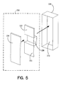
- sound-generating source 220 For the embodiment for which the results are reported in FIG. 9, the application required sound-generating source 220 to generate sound over an extended frequency range at two relatively closely axially spaced positions. Consequently, sound-generating source 220 for that embodiment was a dual cantilevered piezoelectric bending element, which is shown in FIGS. 5-7. This sound-generating source 220 produced the desired frequency output of 3,000 to 5,000 Hz for the particular test application.
- sound-generating source 220 includes two bonded layers: an aluminum plate 224, and a piezoelectric layer 222, which contains two separate portions attached to base element 226.
- sound-generating source 220 contains two separate piezoelectric sources that are built together in a common assembly but act as two nearly independent sound sources.
- Aluminum plate 224 is larger than piezoelectric layer 222, as shown in FIG. 7, so that it creates a lip that overhangs or extends beyond the boundaries of piezoelectric layer 222; however, this lip is not essential for its operation.
- the combination of aluminum plate 224 and piezoelectric layer 222, along with base element 226, are housed within a housing 228, which forms resonator cavity 210.
- the positioning of aluminum plate 224 and piezoelectric layer 222 relative to base element 226 is selected to define the volume of resonator cavity 210.
- the size of aluminum plate 224 and piezoelectric layer 222 are selected to provide a gap between aluminum plate 224 and the side walls of housing 228, as shown in FIGS. 6-7. This gap, most of which is on the ends, defines resonator oriface 270, with the gap size selected accordingly.
- a protective wire-mesh screen 275 covers the front surface of the resonator, which is preferably flush with duct wall 100.
- the key to the extended frequency range of the dual cantilever piezoelectric bending element is the interaction between aluminum plate 224 and piezoelectric layer 222 bimorph and the Helmholtz resonator comprised of resonator cavity 210 and the gap (orifice 270).
- an electric current from output signal 260 passes through the cantilevered piezoelectric layer 222, it and aluminum plate 224 oscillate and become a piston that moves forward and backward, causing decompression and compression of the air in resonator cavity 210.
- the size of the gap (orifice 270) between the cantilevered aluminum plate 224/piezoelectric layer 222 bimorph and the sides of housing 228 is determined such that a Helmholtz resonator is created, which acts as a frequency-dependent impedance match to the vibrating cantilevered piezoelectric layer 224 and thus extends the useful frequency range to well below the natural resonance frequency of the cantilever element.
- resonator cavity 210 The size of resonator cavity 210, the exit area, or size of orifice 270, and other parameters of the system may be selected using standard acoustic analyses for a particular application, as discussed in Beranek, L.L., "Acoustics,” American Institute of Physics, (2d ed.), 1990, pp. 239-258.
- the preferred embodiment of the sound-absorbing segment 400 is shown in greater detail in FIG. 4.
- the sound-absorbing segment 400 comprises a passive nacelle liner having an aluminum or composite sheet with numerous holes 410 layered over a honeycomb backing that forms a system of sound-absorbing resonators 420 that are fixed into place along the interior annulus of duct 100.
- the impervious back plate 430 of sound-absorbing segment 400 isolates the absorber from the remaining nacelle components.
- a honeycomb layer 450 is bonded to backplate 430 to provide structural strength and to create the appropriate volume for the stiffness reactance of sound-absorbing resonators 420.
- a highly porous (large open area) course woven composite sheet 440 is bonded to honeycomb layer 450 to provide additional structural strength ,and some mass reactance for sound-absorbing segment 400.
- a very fine wire mesh screen 460 is bonded to composite sheet 440 to provide the acoustic resistance to accomplish the acoustic energy dissipation for sound-absorbing segment 400.
- FIGS. 8-9 used this type of structure for the sound-absorbing segment 400, which is often referred to as a linear acoustic liner.
- Such liners are advantageous in that the acoustic impedance may be made relatively insensitive to acoustic pressure amplitude, external flow velocity magnitude and duct wall boundary layer thickness.
- the honeycomb layer 450 may be replaced by any structure that sufficiently segments the resonator back cavity of the sound-absorbing resonators 420.
- the course woven composite sheet 440 may be replaced by any highly porous material such as a high open area metallic perforated plate.
- the high acoustic resistance very fine wire mesh 460 may be replaced by any high resistance material, such as a plate with a series of very fine elongated slots.
- the combination of the very fine wire mesh screen 460 bonded to the course woven composite sheet 440 can be replaced by perforated sheet, metallic or composite, which has sufficiently low open area or porosity to provide sufficient acoustic resistance for sound-absorbing segment 400.
- perforated sheet metallic or composite
- An example of a design procedure to achieve a desired acoustic impedance for the wall structure used for the preferred embodiment of sound-absorbing segment 400, with composite sheet 440 replaced by a high-porosity perforated plate, is described in Rice, E. J., "A Model for the Acoustic Impedance of Linear Suppresser Materials Bonded on Perforated Plate", NASA Technical Memorandum 82716, also AIAA Paper Number 81-1999, October 1981.
- the performance of the sound-absorbing segment 400 may be further enhanced by any number of commonly used passive acoustic liner constructions.
- An example is the broadening of the acoustic power bandwidth by properly designing a multiple layered structure made up of two or more layers of honeycomb separated by resistive porous septa to produce a multiple degree-of-freedom sound-absorbing segment 400.
- the sound-absorbing segment 400 may include or solely comprise an active-control system for absorbing the sound field with average propagation angle ⁇ 2 460. While such an active-control system could comprise any active control component(s), it would preferably be an active-control resonator system. One or more of these active-control resonator components could be used in sound-absorbing segment 400, and they may be coupled with any type of passive liner. These active-control components would not perform mode scattering as those in the mode-scattering section; rather, they would be controlled to absorb, reflect or cancel the sound field as used in standard active-control techniques.
- the performance of the overall system is illustrated in the graph shown in FIG. 8.
- the graph shows comparison test results conducted in a NASA Lewis Research Center ANCF 48-inch fan, which generated (4,0) and (4,1) modes over varying frequencies, or fan rotational speeds, ranging from 1750 rpm to slightly less than 1900 rpm.
- the graph contains five separate curves, which shall be discussed from the bottom-most curve upward. As the graph indicates for the bottom-most curve, with neither the passive nor active segment, there was 0-2 dB reduction of noise, or insertion loss. There was no sound-absorbing segment 400 for this curve, and the active-control portion of mode-scattering segment 200 was turned off; however, resonators 210 of the mode-scattering segment 200 absorbed sufficient sound energy operating in a passive mode to provide the small insertion loss shown.
- the second curve moving upwards shows the attenuation of the passive liner used in sound-absorbing segment 400 with the mode-scattering segment 200 inactive.
- the performance of the passive liner ranged from about 3 to 10 dB reduction, depending upon the engine rpm. Note that the performance of the passive liner is very sensitive to frequency changes, a major limitation of all passive liner designs.
- the third curve moving upwards shows the attenuation provided by the active control components 250 of mode-scattering segment 200 operating without the passive liner in sound-absorbing section 400.
- the active-control resonator components 250 did not mode scatter the sound field of the two radial modes, but instead absorbed the sound.
- the insertion loss was 20 to 23 dB over the frequency range tested, a marked improvement over the passive liner alone shown in the curve below.
- the fourth curve moving upwards shows the sum of the insertion loss of the passive liner and the active-control segment. Without the symbiotic mode-scattering/sound-absorbing interaction of the two segments, one would expect the combination of the active and passive segments to achieve an attenuation equal to the sum of the attenuation of the passive liner and the active control component, which ranges from 25 to 31 dB.
- the actual attenuation of the hybrid active-passive sound-absorbing segmented liner system resulted in attenuation of 30 to 36 dB, about 5 dB more attenuation than expected by combining active and passive techniques.
- This increase clearly illustrates that whole of the hybrid system is greater than the sum of its parts, and that there is an unexpected interaction between the active and passive segments. That unexpected interaction is having the active-control portion act to scatter the sound field into higher modes instead of absorbing, reflecting or canceling the noise, thereby greatly increasing the performance of the passive liner.
- FIG. 9 Another similar embodiment was tested in a 22-inch diameter scaled turbofan engine to demonstrate the performance of the preferred embodiment under actual engine running conditions. The results of this test are shown in FIG. 9 for engine speeds ranging from 5,200 rpm to 6,200 rpm, with a mean flow of approximately Mach 0.2 to 0.3, depending upon fan speed.
- the lower curve is a conventional passive liner over the entire engine inlet, which provided about 2 to 9 dB attenuation.
- the upper curve shows the performance of the hybrid mode-scattering/sound-absorbing segmented liner comprised of an active and passive segment.
- the hybrid liner provided about 7 to 18 dB attenuation.
- the present invention shown in FIGS. 1-4 may be used to reduce inlet or exhaust noise, depending upon which side of the rotor-stators the hybrid mode-scattering/sound-absorbing segmented liner is located.
- Each of the two such hybrid liners would likely be designed differently to maximize the sound attenuation for the acoustic characteristics peculiar to inlet and exhaust noise.
- the invention may be used to attenuate noise in any duct.
- the present invention may be used to control excessive noise in heating, ventilation and air-conditioning systems.
- an input microphone or array may be used instead of fan tachometer 230.
- the preferred embodiment of the present invention is particularly directed toward ducts with an air or fluid flow
- those skilled in the art will recognize that the hybrid active-passive sound-absorbing segmented liner system would also perform well to attenuate noise in ducts containing liquids such as hydraulic ducts.
Landscapes
- Engineering & Computer Science (AREA)
- Physics & Mathematics (AREA)
- Acoustics & Sound (AREA)
- Multimedia (AREA)
- Chemical & Material Sciences (AREA)
- Combustion & Propulsion (AREA)
- Mechanical Engineering (AREA)
- General Engineering & Computer Science (AREA)
- Aviation & Aerospace Engineering (AREA)
- Fluid Mechanics (AREA)
- Soundproofing, Sound Blocking, And Sound Damping (AREA)
- Structures Of Non-Positive Displacement Pumps (AREA)
Priority Applications (2)
| Application Number | Priority Date | Filing Date | Title |
|---|---|---|---|
| US08/784,732 US5979593A (en) | 1997-01-13 | 1997-01-13 | Hybrid mode-scattering/sound-absorbing segmented liner system and method |
| EP99307202A EP1085196A1 (de) | 1997-01-13 | 1999-09-13 | Hybrides Moden-streuendes/Schalldämmendes segmentiertes Absorptionseinsatzsystem und Verfahren |
Applications Claiming Priority (2)
| Application Number | Priority Date | Filing Date | Title |
|---|---|---|---|
| US08/784,732 US5979593A (en) | 1997-01-13 | 1997-01-13 | Hybrid mode-scattering/sound-absorbing segmented liner system and method |
| EP99307202A EP1085196A1 (de) | 1997-01-13 | 1999-09-13 | Hybrides Moden-streuendes/Schalldämmendes segmentiertes Absorptionseinsatzsystem und Verfahren |
Publications (1)
| Publication Number | Publication Date |
|---|---|
| EP1085196A1 true EP1085196A1 (de) | 2001-03-21 |
Family
ID=26153570
Family Applications (1)
| Application Number | Title | Priority Date | Filing Date |
|---|---|---|---|
| EP99307202A Withdrawn EP1085196A1 (de) | 1997-01-13 | 1999-09-13 | Hybrides Moden-streuendes/Schalldämmendes segmentiertes Absorptionseinsatzsystem und Verfahren |
Country Status (2)
| Country | Link |
|---|---|
| US (1) | US5979593A (de) |
| EP (1) | EP1085196A1 (de) |
Cited By (8)
| Publication number | Priority date | Publication date | Assignee | Title |
|---|---|---|---|---|
| US7124856B2 (en) * | 2002-10-14 | 2006-10-24 | Rolls-Royce Plc | Acoustic liner for gas turbine engine |
| FR2968048A1 (fr) * | 2010-11-30 | 2012-06-01 | Snecma | Aube de turbomachine comprenant une source electroacoustique amelioree, rangee d'aubes directrices de sortie et turbomachine comprenant une telle aube |
| DE102013225046A1 (de) * | 2013-12-05 | 2015-06-11 | Lufthansa Technik Ag | Flugzeugtriebwerk, Passagierflugzeug, Verfahren zur aktiven Geräuschminderung und Verfahren zum Nachrüsten eines Gasturbinen-Flugzeugtriebwerks |
| US9181875B2 (en) | 2011-04-01 | 2015-11-10 | Alstom Technology Ltd | Gas turbine air intake manifold controllably changing a mechnical rigidity of the walls of said intake manifold |
| CN107545885A (zh) * | 2016-07-03 | 2018-01-05 | 中北大学 | 一种可调频声衬 |
| DE102018103175B3 (de) | 2018-02-13 | 2019-03-21 | Dr. Ing. H.C. F. Porsche Aktiengesellschaft | Rotoranordnung |
| WO2022229596A1 (en) * | 2021-04-29 | 2022-11-03 | Dyson Technology Limited | Noise reduction for air flow devices |
| WO2022229594A1 (en) * | 2021-04-29 | 2022-11-03 | Dyson Technology Limited | Noise reduction for air flow devices |
Families Citing this family (42)
| Publication number | Priority date | Publication date | Assignee | Title |
|---|---|---|---|---|
| US6597792B1 (en) * | 1999-07-15 | 2003-07-22 | Bose Corporation | Headset noise reducing |
| JP3554764B2 (ja) * | 2000-11-20 | 2004-08-18 | 独立行政法人 宇宙航空研究開発機構 | 移動制御反射板を用いたアクティブ吸音パネルシステム |
| US6550574B2 (en) | 2000-12-21 | 2003-04-22 | Dresser-Rand Company | Acoustic liner and a fluid pressurizing device and method utilizing same |
| US6669436B2 (en) * | 2002-02-28 | 2003-12-30 | Dresser-Rand Company | Gas compression apparatus and method with noise attenuation |
| US6896095B2 (en) * | 2002-03-26 | 2005-05-24 | Ford Motor Company | Fan shroud with built in noise reduction |
| US7085388B2 (en) * | 2002-06-14 | 2006-08-01 | The Boeing Company | High frequency jet nozzle actuators for jet noise reduction |
| US6851930B2 (en) * | 2002-09-19 | 2005-02-08 | Motorola, Inc. | Noise reduction in an air moving apparatus |
| US6918740B2 (en) * | 2003-01-28 | 2005-07-19 | Dresser-Rand Company | Gas compression apparatus and method with noise attenuation |
| NL1022647C2 (nl) * | 2003-02-11 | 2004-08-12 | Tno | Inrichting voor het actief reduceren van geluidstransmissie, alsmede een paneel omvattende een dergelijke inrichting. |
| DE102004046200A1 (de) * | 2004-09-22 | 2006-04-06 | Carcoustics Tech Center Gmbh | Mobiler Prüfstand zur Bestimmung der Schalldämmung oder Einfügungsdämmung eines Prüfobjekts |
| US20060169532A1 (en) * | 2005-02-03 | 2006-08-03 | Patrick William P | Acoustic liner with nonuniform impedance |
| US20060169533A1 (en) * | 2005-02-03 | 2006-08-03 | Patrick William P | Acoustic liner with a nonuniform depth backwall |
| US20060269090A1 (en) * | 2005-05-27 | 2006-11-30 | Roman Sapiejewski | Supra-aural headphone noise reducing |
| US20080140888A1 (en) * | 2006-05-30 | 2008-06-12 | Schneider Automation Inc. | Virtual Placeholder Configuration for Distributed Input/Output Modules |
| US7970148B1 (en) * | 2007-05-31 | 2011-06-28 | Raytheon Company | Simultaneous enhancement of transmission loss and absorption coefficient using activated cavities |
| US7777640B2 (en) * | 2007-07-31 | 2010-08-17 | Tryggvi Emilsson | Use of heating and/or ventilation ductwork to broadcast alarm conditions |
| US8111832B2 (en) * | 2008-04-16 | 2012-02-07 | The United States Of America As Represented By The Administrator Of The National Aeronautics And Space Administration | Method of adjusting acoustic impedances for impedance-tunable acoustic segments |
| US20110161538A1 (en) * | 2009-12-31 | 2011-06-30 | Schneider Electric USA, Inc. | Method and System for Implementing Redundant Network Interface Modules in a Distributed I/O System |
| US8955643B2 (en) | 2011-04-20 | 2015-02-17 | Dresser-Rand Company | Multi-degree of freedom resonator array |
| US8826669B2 (en) * | 2011-11-09 | 2014-09-09 | Pratt & Whitney Canada Corp. | Gas turbine exhaust case |
| US20130306400A1 (en) * | 2012-05-16 | 2013-11-21 | Alan S. Hersh | Method of Designing and Making an Acoustic Liner for Jet Aircraft Engines |
| EP3828382B1 (de) | 2013-03-15 | 2023-08-09 | Raytheon Technologies Corporation | Gasturbinenschaufel mit reduzierter akustischer leistung |
| WO2014197035A2 (en) | 2013-03-15 | 2014-12-11 | United Technologies Corporation | Acoustic liner with varied properties |
| US9856030B2 (en) * | 2014-11-26 | 2018-01-02 | Rohr, Inc. | Acoustic attenuation with adaptive impedance |
| US10941708B2 (en) * | 2017-03-07 | 2021-03-09 | Raytheon Technologies Corporation | Acoustically damped gas turbine engine |
| US10422280B2 (en) | 2017-03-07 | 2019-09-24 | United Technologies Corporation | Fan flutter suppression system |
| US10539156B2 (en) | 2017-03-07 | 2020-01-21 | United Technologies Corporation | Variable displacement flutter damper for a turbofan engine |
| US10415506B2 (en) | 2017-03-07 | 2019-09-17 | United Technologies Corporation | Multi degree of freedom flutter damper |
| US10428685B2 (en) | 2017-03-07 | 2019-10-01 | United Technologies Corporation | Flutter inhibiting intake for gas turbine propulsion system |
| US10612464B2 (en) | 2017-03-07 | 2020-04-07 | United Technologies Corporation | Flutter inhibiting intake for gas turbine propulsion system |
| US10619566B2 (en) * | 2017-03-07 | 2020-04-14 | United Technologies Corporation | Flutter damper for a turbofan engine |
| JP6689241B2 (ja) | 2017-09-15 | 2020-04-28 | 株式会社東芝 | 騒音低減装置、飛行体、発電装置、騒音低減方法及び騒音低減プログラム |
| US10677163B2 (en) * | 2017-12-06 | 2020-06-09 | General Electric Company | Noise attenuation structures |
| FR3078744B1 (fr) * | 2018-03-08 | 2020-11-20 | Safran Nacelles | Dispositif actif d’attenuation des emissions acoustiques pour un turboreacteur comportant des turbines controlees |
| TWI705188B (zh) * | 2018-08-01 | 2020-09-21 | 緯創資通股份有限公司 | 風扇系統與風扇系統的抑音方法 |
| NL2021916B1 (en) * | 2018-11-01 | 2020-05-14 | Univ Delft Tech | Acoustic Liner |
| RU2732532C1 (ru) * | 2019-04-23 | 2020-09-21 | федеральное государственное бюджетное образовательное учреждение высшего образования "Пермский национальный исследовательский политехнический университет" | Резонансная ячейка для гашения акустических волн |
| FR3103953B1 (fr) * | 2019-11-29 | 2021-11-12 | Safran Aircraft Engines | Pastille résonante et cellule de traitement acoustique dotée d’une telle pastille |
| CN112069657B (zh) * | 2020-08-13 | 2024-03-12 | 株洲时代新材料科技股份有限公司 | 适用于气流环境下管道声衬设计方法及管道声衬 |
| CN112834997B (zh) * | 2021-01-07 | 2023-08-18 | 中国航发沈阳发动机研究所 | 一种具有矩形开口特征的低散射载体外形设计方法 |
| CN112987508B (zh) * | 2021-03-04 | 2022-09-30 | 长鑫存储技术有限公司 | 振动衰减结构及曝光装置 |
| CN114354766B (zh) * | 2021-12-30 | 2024-05-03 | 中国特种设备检测研究院 | 一种超声探头阻尼背衬的制造方法 |
Citations (4)
| Publication number | Priority date | Publication date | Assignee | Title |
|---|---|---|---|---|
| US3937590A (en) * | 1974-09-03 | 1976-02-10 | General Electric Company | Acoustic duct with peripherally segmented acoustic treatment |
| US5119427A (en) * | 1988-03-14 | 1992-06-02 | Hersh Alan S | Extended frequency range Helmholtz resonators |
| US5702230A (en) * | 1996-01-29 | 1997-12-30 | General Electric Company | Actively controlled acoustic treatment panel |
| US5782082A (en) * | 1996-06-13 | 1998-07-21 | The Boeing Company | Aircraft engine acoustic liner |
Family Cites Families (16)
| Publication number | Priority date | Publication date | Assignee | Title |
|---|---|---|---|---|
| US3936606A (en) * | 1971-12-07 | 1976-02-03 | Wanke Ronald L | Acoustic abatement method and apparatus |
| US3946830A (en) * | 1974-09-06 | 1976-03-30 | General Electric Company | Inlet noise deflector |
| US4044263A (en) * | 1975-01-28 | 1977-08-23 | Walter Kidde & Company, Inc. | Ionization dual-zone static detector having single radioactive source |
| US4192336A (en) * | 1975-12-29 | 1980-03-11 | The Boeing Company | Noise suppression refracting inlet for jet engines |
| GB1583758A (en) * | 1976-10-01 | 1981-02-04 | Nat Res Dev | Attenuation of sound waves in ducts |
| FR2370170A1 (fr) * | 1976-11-05 | 1978-06-02 | Snecma | Procede et dispositif pour la diminution du bruit des turbomachines |
| FR2370171A1 (fr) * | 1976-11-05 | 1978-06-02 | Snecma | Procede et dispositif pour la diminution du bruit des turbomachines |
| US4104002A (en) * | 1976-12-02 | 1978-08-01 | General Electric Company | Spiral strip acoustic treatment |
| JPS62164400A (ja) * | 1986-01-14 | 1987-07-21 | Hitachi Plant Eng & Constr Co Ltd | 電子消音システム |
| US5060471A (en) * | 1989-11-06 | 1991-10-29 | 501 Nordam | Jet engine noise reduction system |
| USH1357H (en) * | 1990-08-27 | 1994-09-06 | The United States Of America As Represented By The Secretary Of The Navy | Active sound cancellation system for time-varying signals |
| US5370340A (en) * | 1991-11-04 | 1994-12-06 | General Electric Company | Active control of aircraft engine noise using vibrational inputs |
| US5377275A (en) * | 1992-07-29 | 1994-12-27 | Kabushiki Kaisha Toshiba | Active noise control apparatus |
| US5325661A (en) * | 1993-04-14 | 1994-07-05 | The United States Of America As Represented By The Administrator Of The National Aeronautics And Space Administration | Jet mixer noise suppressor using acoustic feedback |
| US5382134A (en) * | 1993-11-01 | 1995-01-17 | General Electric Company | Active noise control using noise source having adaptive resonant frequency tuning through stiffness variation |
| US5498127A (en) * | 1994-11-14 | 1996-03-12 | General Electric Company | Active acoustic liner |
-
1997
- 1997-01-13 US US08/784,732 patent/US5979593A/en not_active Expired - Fee Related
-
1999
- 1999-09-13 EP EP99307202A patent/EP1085196A1/de not_active Withdrawn
Patent Citations (4)
| Publication number | Priority date | Publication date | Assignee | Title |
|---|---|---|---|---|
| US3937590A (en) * | 1974-09-03 | 1976-02-10 | General Electric Company | Acoustic duct with peripherally segmented acoustic treatment |
| US5119427A (en) * | 1988-03-14 | 1992-06-02 | Hersh Alan S | Extended frequency range Helmholtz resonators |
| US5702230A (en) * | 1996-01-29 | 1997-12-30 | General Electric Company | Actively controlled acoustic treatment panel |
| US5782082A (en) * | 1996-06-13 | 1998-07-21 | The Boeing Company | Aircraft engine acoustic liner |
Cited By (10)
| Publication number | Priority date | Publication date | Assignee | Title |
|---|---|---|---|---|
| US7124856B2 (en) * | 2002-10-14 | 2006-10-24 | Rolls-Royce Plc | Acoustic liner for gas turbine engine |
| FR2968048A1 (fr) * | 2010-11-30 | 2012-06-01 | Snecma | Aube de turbomachine comprenant une source electroacoustique amelioree, rangee d'aubes directrices de sortie et turbomachine comprenant une telle aube |
| US9181875B2 (en) | 2011-04-01 | 2015-11-10 | Alstom Technology Ltd | Gas turbine air intake manifold controllably changing a mechnical rigidity of the walls of said intake manifold |
| DE102013225046A1 (de) * | 2013-12-05 | 2015-06-11 | Lufthansa Technik Ag | Flugzeugtriebwerk, Passagierflugzeug, Verfahren zur aktiven Geräuschminderung und Verfahren zum Nachrüsten eines Gasturbinen-Flugzeugtriebwerks |
| CN107545885A (zh) * | 2016-07-03 | 2018-01-05 | 中北大学 | 一种可调频声衬 |
| CN107545885B (zh) * | 2016-07-03 | 2020-09-01 | 中北大学 | 一种可调频声衬 |
| DE102018103175B3 (de) | 2018-02-13 | 2019-03-21 | Dr. Ing. H.C. F. Porsche Aktiengesellschaft | Rotoranordnung |
| WO2022229596A1 (en) * | 2021-04-29 | 2022-11-03 | Dyson Technology Limited | Noise reduction for air flow devices |
| WO2022229594A1 (en) * | 2021-04-29 | 2022-11-03 | Dyson Technology Limited | Noise reduction for air flow devices |
| US12270420B2 (en) | 2021-04-29 | 2025-04-08 | Dyson Technology Limited | Noise reduction for air flow devices |
Also Published As
| Publication number | Publication date |
|---|---|
| US5979593A (en) | 1999-11-09 |
Similar Documents
| Publication | Publication Date | Title |
|---|---|---|
| US5979593A (en) | Hybrid mode-scattering/sound-absorbing segmented liner system and method | |
| US5355417A (en) | Active control of aircraft engine inlet noise using compact sound sources and distributed error sensors | |
| US5515444A (en) | Active control of aircraft engine inlet noise using compact sound sources and distributed error sensors | |
| US5119427A (en) | Extended frequency range Helmholtz resonators | |
| JP3554764B2 (ja) | 移動制御反射板を用いたアクティブ吸音パネルシステム | |
| EP0712114A2 (de) | Aktiver akustischer Uberzug | |
| US5702230A (en) | Actively controlled acoustic treatment panel | |
| Palleja-Cabre et al. | Modelling of over-the-rotor acoustic treatments for improved noise suppression in turbofan engines | |
| Xiong et al. | Effects of turbofan engine intake droop and length on fan tone noise | |
| Gerhold | Active control of fan-generated tone noise | |
| Liu et al. | Reactive control of subsonic axial fan noise in a duct | |
| Smith et al. | Experiments on the active control of inlet noise from a turbofan jet engine using multiple circumferential control arrays | |
| Nagai et al. | Acoustic liner test of DGEN 380 turbofan engine | |
| Brown et al. | Offset Stream Technologies Test-Summary of Results | |
| Nallasamy et al. | Propagation of spinning acoustic modes in turbofan exhaust ducts | |
| Remington et al. | Active control of low-speed fan tonal noise using actuators mounted in stator vanes: part 1 control system design and implementation | |
| Parente et al. | Hybrid active/passive jet engine noise suppression system | |
| Behn et al. | Experimental investigation of mode-frequency scattering at fan stages | |
| Lester et al. | Duct liner optimization for turbomachinery noise sources | |
| Risi et al. | Analytical investigation of active control of radiated inlet fan noise | |
| Minter et al. | Active control of turbomachine discrete frequency noise utilizing oscillating flaps and pistons | |
| Sawyer et al. | Active control of discrete-frequency noise generated by rotor-stator interactions | |
| Marsh | Study of Acoustical Treatments for Jet‐Engine Nacelles | |
| Sawyer et al. | Active control of discrete-frequency noise generated by rotor-stator interactions | |
| Sawdy et al. | Optimum segmented acoustic liners for flow ducts |
Legal Events
| Date | Code | Title | Description |
|---|---|---|---|
| PUAI | Public reference made under article 153(3) epc to a published international application that has entered the european phase |
Free format text: ORIGINAL CODE: 0009012 |
|
| AK | Designated contracting states |
Kind code of ref document: A1 Designated state(s): AT BE CH CY DE DK ES FI FR GB GR IE IT LI LU MC NL PT SE |
|
| AX | Request for extension of the european patent |
Free format text: AL;LT;LV;MK;RO;SI |
|
| AKX | Designation fees paid | ||
| STAA | Information on the status of an ep patent application or granted ep patent |
Free format text: STATUS: THE APPLICATION IS DEEMED TO BE WITHDRAWN |
|
| 18D | Application deemed to be withdrawn |
Effective date: 20010922 |
|
| REG | Reference to a national code |
Ref country code: DE Ref legal event code: 8566 |