EP1085137A1 - An insulating enbloc for buildings - Google Patents
An insulating enbloc for buildings Download PDFInfo
- Publication number
- EP1085137A1 EP1085137A1 EP99830558A EP99830558A EP1085137A1 EP 1085137 A1 EP1085137 A1 EP 1085137A1 EP 99830558 A EP99830558 A EP 99830558A EP 99830558 A EP99830558 A EP 99830558A EP 1085137 A1 EP1085137 A1 EP 1085137A1
- Authority
- EP
- European Patent Office
- Prior art keywords
- insulating body
- enbloc
- block
- mechanical coupling
- insulating
- Prior art date
- Legal status (The legal status is an assumption and is not a legal conclusion. Google has not performed a legal analysis and makes no representation as to the accuracy of the status listed.)
- Granted
Links
- 230000008878 coupling Effects 0.000 claims abstract description 87
- 238000010168 coupling process Methods 0.000 claims abstract description 87
- 238000005859 coupling reaction Methods 0.000 claims abstract description 87
- 125000006850 spacer group Chemical group 0.000 claims description 22
- 238000000034 method Methods 0.000 claims description 20
- 239000011810 insulating material Substances 0.000 description 8
- 238000004519 manufacturing process Methods 0.000 description 8
- 239000004927 clay Substances 0.000 description 7
- 239000011449 brick Substances 0.000 description 5
- 238000010276 construction Methods 0.000 description 5
- 239000000463 material Substances 0.000 description 4
- 238000005273 aeration Methods 0.000 description 3
- 230000015572 biosynthetic process Effects 0.000 description 3
- 238000005520 cutting process Methods 0.000 description 2
- 238000009413 insulation Methods 0.000 description 2
- 230000002093 peripheral effect Effects 0.000 description 2
- 229920006327 polystyrene foam Polymers 0.000 description 2
- 239000004793 Polystyrene Substances 0.000 description 1
- 230000001154 acute effect Effects 0.000 description 1
- 230000006978 adaptation Effects 0.000 description 1
- 238000003490 calendering Methods 0.000 description 1
- 238000007796 conventional method Methods 0.000 description 1
- 239000007799 cork Substances 0.000 description 1
- 238000001035 drying Methods 0.000 description 1
- 230000000694 effects Effects 0.000 description 1
- 238000003780 insertion Methods 0.000 description 1
- 230000037431 insertion Effects 0.000 description 1
- 239000000203 mixture Substances 0.000 description 1
- 238000000465 moulding Methods 0.000 description 1
- 230000035515 penetration Effects 0.000 description 1
- 239000004033 plastic Substances 0.000 description 1
- 229920002223 polystyrene Polymers 0.000 description 1
- 239000007787 solid Substances 0.000 description 1
- 238000007711 solidification Methods 0.000 description 1
- 230000008023 solidification Effects 0.000 description 1
- 238000003892 spreading Methods 0.000 description 1
- 230000007480 spreading Effects 0.000 description 1
- 239000000126 substance Substances 0.000 description 1
Images


Classifications
-
- E—FIXED CONSTRUCTIONS
- E04—BUILDING
- E04C—STRUCTURAL ELEMENTS; BUILDING MATERIALS
- E04C1/00—Building elements of block or other shape for the construction of parts of buildings
- E04C1/40—Building elements of block or other shape for the construction of parts of buildings built-up from parts of different materials, e.g. composed of layers of different materials or stones with filling material or with insulating inserts
- E04C1/41—Building elements of block or other shape for the construction of parts of buildings built-up from parts of different materials, e.g. composed of layers of different materials or stones with filling material or with insulating inserts composed of insulating material and load-bearing concrete, stone or stone-like material
-
- E—FIXED CONSTRUCTIONS
- E04—BUILDING
- E04B—GENERAL BUILDING CONSTRUCTIONS; WALLS, e.g. PARTITIONS; ROOFS; FLOORS; CEILINGS; INSULATION OR OTHER PROTECTION OF BUILDINGS
- E04B2/00—Walls, e.g. partitions, for buildings; Wall construction with regard to insulation; Connections specially adapted to walls
- E04B2/02—Walls, e.g. partitions, for buildings; Wall construction with regard to insulation; Connections specially adapted to walls built-up from layers of building elements
- E04B2002/0202—Details of connections
- E04B2002/0204—Non-undercut connections, e.g. tongue and groove connections
- E04B2002/0208—Non-undercut connections, e.g. tongue and groove connections of trapezoidal shape
-
- E—FIXED CONSTRUCTIONS
- E04—BUILDING
- E04B—GENERAL BUILDING CONSTRUCTIONS; WALLS, e.g. PARTITIONS; ROOFS; FLOORS; CEILINGS; INSULATION OR OTHER PROTECTION OF BUILDINGS
- E04B2/00—Walls, e.g. partitions, for buildings; Wall construction with regard to insulation; Connections specially adapted to walls
- E04B2/02—Walls, e.g. partitions, for buildings; Wall construction with regard to insulation; Connections specially adapted to walls built-up from layers of building elements
- E04B2002/0202—Details of connections
- E04B2002/0204—Non-undercut connections, e.g. tongue and groove connections
- E04B2002/0228—Non-undercut connections, e.g. tongue and groove connections with tongues next to each other on one end surface and grooves next to each other on opposite end surface
Definitions
- the present invention relates to an insulating enbloc for buildings comprising the characteristics expressed in the preamble to claim 13.
- the present invention further relates to a method for the realisation of an enbloc for buildings comprising the characteristics expressed in the preamble to claim 1.
- the present invention is suitable for use in the construction industry and specifically for constructions such as houses, buildings and similar infrastructures requiring adequate thermal and/or acoustic insulation with respect to the surrounding environment.
- the construction of the peripheral walls of the aforementioned buildings is accomplished by forming primarily a first wall destined to constitute the inner face of the wall, comprising bricks stacked vertically according to horizontal courses. On the outer side of the first wall is subsequently applied, with appropriate fastening means, a series of insulating panels in such a way as to define a substantially continuous insulating layer. A second wall of bricks is then erected, destined to constitute the outer face of the wall.
- the second brick wall can be realised directly against the insulating panels forming a single body, or it can be realised at a pre-set distance from the insulating panel so as to define a gap for aeration and/or the placement of electrical elements or elements of other kinds.
- Another known and widely used technique for the realisation of insulating walls entails forming an inner wall of bricks and, subsequently, an outer wall of bricks distanced therefrom, to define a gap between the two. In the gap is then poured an expandable insulating material which solidifies, consequently defining an insulating layer.
- the Applicant has introduced on the market a type of insulating enbloc for buildings substantially comprising two small blocks usually made of tile material such as mixed clay, between which is interposed a body of insulating material constituted by polystyrene foam.
- Such enblocs are realised by positioning a first and a second clay block at a pre-set mutual distance so as to define a gap between them.
- a predefined quantity of insulating material in granular form which is expanded by means of a flow of steam made to pass through the insulating material itself.
- the insulating material solidifies defining a solid insulating block which remains permanently engaged to the blocks.
- the union between the insulating body and the blocks of the insulating enbloc is assured by suitable undercuts defined by dovetail grooves provided on the mutually opposite sides of the blocks.
- the aforementioned insulating enblocs allow the realisation of insulating peripheral walls with a single laying operation of the enblocs themselves, stacked and fastened one adjacently to the other according to successively superposed courses.
- a first part and a second part, respectively oriented towards the interior and the exterior of the construction, are defined respectively by the first and by the second clay block of each enbloc, and a third part, interposed between the first and the second part, is defined by the set of insulating bodies which consequently form an insulating layer extending according to the entire extension of the wall.
- the current method for the realisation of insulating enblocs presents a series of limitations relating to the time required for production since it is necessary, after forming the two clay blocks, to position them at a precise mutual distance, and then to proceed with forming the insulating body.
- the precise positioning of a block with respect to the other entails, in itself, a slowdown in the production cycle of the insulating enbloc which is further slowed by the insulating body formation stage.
- the formation of the insulating body requires relatively high waiting times to allow for the expansion of the insulating material and its subsequent solidification.
- the technical task constituting the basis for the present invention is to devise an insulating enbloc for buildings that is able substantially to overcome the aforementioned drawbacks.
- an important aim of the invention is to devise an insulating enbloc for buildings that presents optimal heat-insulating and sound-insulating characteristics and that can be manufactured rapidly with modest production costs.
- Another important aim of the invention is to devise an insulating enbloc for buildings that can be realised with an insulating layer of any material and/or thickness without entailing particular complications for the adaptation of the machinery to the type of item in production.
- the enbloc 1 comprises a first block 2 preferably made of clay presenting a plurality of lightening through openings 2a oriented vertically.
- the enbloc 1 further comprises a second block 3 engaged to the first block 2, also preferably made of clay and presenting a series of lightening through openings 3a.
- the first and the second block 2, 3 are mutually engaged by means of the interposition of at least an insulating body 4 which can be made of different materials depending on the technical requirements to be met.
- the enbloc 1 provides for the presence of at least a first and a second mechanical coupling elements 5 fastened respectively in correspondence with opposite sides of the insulating body 4.
- each block 2, 3 is fastened to the insulating body 4 by means of at least two mechanical coupling elements 5 appropriately distanced from each other.
- Each mechanical coupling element 5 presents at least an attachment portion 5a for fastening itself to the insulating body 4 and at least a coupling portion 5b destined to engage at least a respective coupling seat 6 obtained in the corresponding block 2, 3.
- each mechanical coupling element 5 and the insulating body 4 is secured by means of at least a mechanical fastening element 7 operatively engaged between the insulating body 4 and the attachment portion 5a of the mechanical fastening element itself.
- each mechanical fastening element 7 is set to make fast, with respect to the insulating body 4, in correspondence with opposite sides thereof, two mechanical coupling elements 5. More specifically, each mechanical fastening element 7 extends through the insulating body 4 and presents a first and a second extremity 7a, 7b set to retain the respective mechanical coupling elements 5 with respect to the insulating body 4.
- each mechanical coupling element 5 is rigidly associated to the insulating body 4 by means of two mechanical fastening elements 7 set parallel and mutually distanced in such a way as to prevent the fastening element from rotating in undesirable manners.
- tubular spacers 8 can be provided, each positioned around a respective mechanical fastening element 7.
- each spacer 8 is co-axially inserted on the respective mechanical fastening element 7 and presents a length substantially no lesser than the thickness of the insulating body 4.
- Each spacer 8 further presents respective opposite extremities 8a in contact relationship with the attachment portions 5a of the respective mechanical coupling elements 5.
- each spacer 8 associated to the respective mechanical fastening element 7 is realised in such a way as to have a length greater than the thickness of the insulating body 4 (see Figure 2). In this way it is possible to obtain between the insulating body 4 and at least one of the blocks 2, 3, a gap 9 for aeration and/or for inserting - as required - pipelines, electrical cables, or other elements into the wall to be built.
- the gap 9 can be realised between the first block and the insulating body 4 or, if necessary, two gaps 9 can be realised, respectively interposed between the blocks 2, 3 and the insulating body 4.
- a known securing element 9a is externally engaged to each spacer 8 to prevent the insulating body 4 from sliding along the spacers themselves. More specifically, the securing elements 9a are engaged to the spacers 8 in correspondence with the side of the insulating body 4 that faces the gap 9. When two gaps 9 are provided, on each spacer 8 are engaged two securing elements 9a situated respectively against the opposite sides of the insulating body 4. These securing elements 9a hold the insulating body fast with respect to the spacers themselves in the desired position.
- each mechanical fastening element 7 comprises a rivet which is fastened to the insulating body 4 and to the respective mechanical coupling elements 5 according to a method which will be described farther on.
- each mechanical coupling element 5 can comprise an elastically yielding deformed laminar element, whose coupling portion is defined by lateral tabs 5b converging symmetrically away from the attachment portion 5a, according to a substantially transverse orientation.
- the lateral tabs 5b are provided with folded back terminal portions 5c presenting for instance a rounded profile (Figure 1) or an acute angle profile ( Figure 2), set to engage respective strike portions 6a obtained in the coupling seat 6 substantially defined by a recess provided with receiving surfaces 6b diverging externally with respect to block 2, 3, towards the insulating body 4.
- the lateral tabs 5b of each coupling element 5 are elastically pressed against one another by sliding with interference on the receiving surfaces 6b of the coupling seat 6.
- the terminal portions of the lateral tabs 5b reach the strike portions 6a they snap elastically, engaging the strike portions 6a as stated above. Once they have snapped, the lateral tabs 5b interact with the strike portions 6a of the respective coupling seat 6 to hold the insulating body fast to the respective block 2, 3.
- Figure 3 shows a third embodiment which provides for each mechanical coupling element 5 to comprise a laminar element which may be rigid, set to be inserted by sliding into the respective coupling seat 6.
- the coupling seat is shaped in the manner of a through groove with two lateral surfaces 6b converging externally to the respective block 2, 3 i.e. towards the insulating body 4, to form an undercut in the coupling seat itself.
- Each rigid laminar element presents as a coupling portion 5b interference tabs which diverge symmetrically away from the attachment portion 5a according to a substantially transverse orientation with respect thereto.
- the insulating body 4 is made fast to the respective blocks 2, 3 by inserting the laminar elements 5 into the corresponding coupling seats 6, determining a relative sliding between the insulating body 4 and the blocks themselves on the plane of their sides that face each other.
- FIG 4 shows a fourth embodiment wherein each mechanical coupling element 5 comprises a laminar element, elastically yielding, presenting lateral tabs 5b extending symmetrically from the attachment portion 5a and provided with respective terminal appendices 5c substantially oriented one towards the other.
- the coupling seats 6 comprise coupling projections 6c destined operatively to engage the respective laminar element 5.
- each coupling projection 6c is inserted between the lateral tabs 5b of the respective laminar elements 5 spreading the lateral tabs themselves.
- the realisation of the insulating enbloc 1 requires first the formation of the first and second block 2,3, usually obtainable by extruding a clay mixture and subsequently drying and baking, as well as of the insulating body 4.
- the insulating body 4, formed as a distinct, separate element from the blocks 2, 3, is preferably realised in the form of a rectangular panel, for instance made of polystyrene, cork or any other insulating material, obtained for instance by means of moulding, calendering or any other conventional technique.
- a plurality of insulating bodies 4 can be obtained by a simple cutting or die-cutting operation of a single previously formed panel.
- the mechanical coupling elements 5 and the mechanical fastening elements 7 are also realised separately from the insulating body 4 and from the blocks 2, 3.
- the insulating body 4 is readied for assembly with the blocks 2, 3 by fastening the mechanical coupling elements 5 on the opposite sides of the insulating body itself.
- each mechanical coupling element 5 For purposes of fastening each mechanical coupling element 5, it is preferably provided for the rivets or equivalent mechanical fastening elements 7 to be first fitted onto respective centring stems 10 set on an assembling apparatus. A first mechanical coupling element 5 is then engaged on the rivets 7 in such a way that each of the rivets is inserted in a through hole obtained in the attachment portion 5a of the coupling element itself, bringing its head 7a in contact relationship with the aforesaid attachment portion, as per Figure 6.
- each rivet 7 is fitted the respective tubular spacer 8, in such a way that a strike extremity 8a thereof is positioned in contact against the attachment portion 5a on the side opposite to the head 7a of the rivet 7, as per Figure 6.
- the insulating body 4 is then fitted onto the spacer 8 in such a way as to determine its engagement with the rivets 7 and the mechanical coupling element 5. More specifically, in this phase each rivet 7 with the respective spacer 8 are inserted in a through hole provided in the insulating body 4, as per Figure 7.
- the spacers 8 can first be inserted through the insulating body 4, then fitted onto the rivets 7 together with the insulating body itself.
- a terminal edge of the second extremity 7b of each rivet 7, opposite to the first coupling element 5 is then folded back, to determine the definitive fastening of the coupling element 5 to the insulating body 4.
- This phase can be implemented, for instance, using a cold-forming punch towards an insulating body 4 to determine the plastic deformation of the second extremity 7b of the rivet 7.
- the presence of the spacers 8 eliminates the risk that the structure of the insulating body 4 may collapse as an effect of the thrusts transmitted to the mechanical coupling elements 5, with consequent partial sinking thereof into the surface of the insulating body itself.
- At least one mill 11 is used, presenting a conical working portion 11a, eccentric with respect to the axis of rotation of the mill itself.
- the eccentric rotation of the conical working portion 11a determines the terminal portion of the rivet 7 to be bent as a result of the axial approach of the mill 11 towards the rivet itself, as clearly visible in Figures 9 and 10, without transmitting relevant thrust actions on the mechanical coupling elements 5.
- the insulating body 4 is interposed between the blocks 2, 3 previously positioned one in front of the other, at a greater mutual distance than the distance measurable between the attachment portions 5a of the coupling elements 5 situated to the opposite sides of the insulating body 4.
- the blocks 2, 3 are then forcibly approached to the insulating body 4, determining the snapping engagement of the lateral tabs 5b into the respective coupling seats 6.
- the presence of the spacers 8 is useful in protecting the insulating body 4 against excessive stresses, eliminating all risks of penetration by the mechanical coupling elements 5 into the surface of the insulating body itself which would compromise the correct engagement of the coupling elements in the respective seats 6.
- the blocks 2, 3 are first positioned one in front of the other at a mutual distance substantially corresponding to the thickness of the insulating body 4, i.e. to the distance measurable between the attachment portions 5a of the coupling elements 5.
- the insulating body 4 is then inserted between the blocks 2, 3, determining the sliding engagement of the coupling elements 5 in the respective seats 6.
- the engagement of the blocks 2, 3 to the insulating body 4 is preferably effected simultaneously in a single phase, but the possibility of determining the engagement of the individual blocks 3 in successive phases is not excluded.
- the present invention attains important advantages.
- the invention brings about considerable improvements in relation to the time required to produce the enblocs.
- the subject method does not call for productive phases that require long waiting times for the realisation of the insulating phase. All the phases of the assembly of the enbloc can instead be executed in an extremely simple and fast manner.
- the invention allows to provide an aeration gap inside the enbloc, which could not be achieved in the prior art, where the insulating layer was formed directly by filling the space defined between the blocks positioned one in front of the other.
Landscapes
- Engineering & Computer Science (AREA)
- Architecture (AREA)
- Civil Engineering (AREA)
- Structural Engineering (AREA)
- Building Environments (AREA)
- Ventilation (AREA)
- Transforming Light Signals Into Electric Signals (AREA)
Abstract
Description
- The present invention relates to an insulating enbloc for buildings comprising the characteristics expressed in the preamble to claim 13.
- The present invention further relates to a method for the realisation of an enbloc for buildings comprising the characteristics expressed in the preamble to claim 1. In particular, the present invention is suitable for use in the construction industry and specifically for constructions such as houses, buildings and similar infrastructures requiring adequate thermal and/or acoustic insulation with respect to the surrounding environment.
- Normally, the construction of the peripheral walls of the aforementioned buildings is accomplished by forming primarily a first wall destined to constitute the inner face of the wall, comprising bricks stacked vertically according to horizontal courses. On the outer side of the first wall is subsequently applied, with appropriate fastening means, a series of insulating panels in such a way as to define a substantially continuous insulating layer. A second wall of bricks is then erected, destined to constitute the outer face of the wall. The second brick wall can be realised directly against the insulating panels forming a single body, or it can be realised at a pre-set distance from the insulating panel so as to define a gap for aeration and/or the placement of electrical elements or elements of other kinds.
- Another known and widely used technique for the realisation of insulating walls entails forming an inner wall of bricks and, subsequently, an outer wall of bricks distanced therefrom, to define a gap between the two. In the gap is then poured an expandable insulating material which solidifies, consequently defining an insulating layer.
- To obtain a better insulation and simplify construction operations, the Applicant has introduced on the market a type of insulating enbloc for buildings substantially comprising two small blocks usually made of tile material such as mixed clay, between which is interposed a body of insulating material constituted by polystyrene foam.
- Such enblocs are realised by positioning a first and a second clay block at a pre-set mutual distance so as to define a gap between them. Into the gap is poured a predefined quantity of insulating material in granular form which is expanded by means of a flow of steam made to pass through the insulating material itself. Simultaneously with its expansion, the insulating material solidifies defining a solid insulating block which remains permanently engaged to the blocks. The union between the insulating body and the blocks of the insulating enbloc is assured by suitable undercuts defined by dovetail grooves provided on the mutually opposite sides of the blocks.
- The aforementioned insulating enblocs allow the realisation of insulating peripheral walls with a single laying operation of the enblocs themselves, stacked and fastened one adjacently to the other according to successively superposed courses.
- Once the masonry is completed, it can be distinguished in three parts. A first part and a second part, respectively oriented towards the interior and the exterior of the construction, are defined respectively by the first and by the second clay block of each enbloc, and a third part, interposed between the first and the second part, is defined by the set of insulating bodies which consequently form an insulating layer extending according to the entire extension of the wall.
- Although the insulating enblocs indicated above are particularly well suited to realise in a practical and easy manner thermo-insulating walls with very good physical, chemical and mechanical qualities, such enblocs are nonetheless not wholly free of some drawbacks.
- In particular, the current method for the realisation of insulating enblocs presents a series of limitations relating to the time required for production since it is necessary, after forming the two clay blocks, to position them at a precise mutual distance, and then to proceed with forming the insulating body. The precise positioning of a block with respect to the other entails, in itself, a slowdown in the production cycle of the insulating enbloc which is further slowed by the insulating body formation stage. The formation of the insulating body requires relatively high waiting times to allow for the expansion of the insulating material and its subsequent solidification.
- The Applicant has observed that it is possible to improve the production of the insulating enblocs described above, considerably reducing their realisation time. In addition to the problem described above, it should be considered that for the realisation of the insulating enblocs it is necessary to have available complex production facilities calling for the presence of expensive and bulky machinery.
- It should further be considered that the production of enblocs provided with insulating body like the one described does not allow the use of insulating materials other than polystyrene foam. This is a considerable disadvantage since it is not possible to produce items presenting different heat-insulating and/or sound-insulating characteristics, forcing the manufacturer to market only one kind of item.
- The technical task constituting the basis for the present invention is to devise an insulating enbloc for buildings that is able substantially to overcome the aforementioned drawbacks.
- Within the scope of said technical task, an important aim of the invention is to devise an insulating enbloc for buildings that presents optimal heat-insulating and sound-insulating characteristics and that can be manufactured rapidly with modest production costs.
- Another important aim of the invention is to devise an insulating enbloc for buildings that can be realised with an insulating layer of any material and/or thickness without entailing particular complications for the adaptation of the machinery to the type of item in production.
- The technical task set out herein and the specified aims are substantially attained by a method for the realisation of an insulating enbloc for buildings comprising the characteristics expressed in the characterising part of
claim 1. - The technical task set out herein and the specified aims are further attained by an insulating enbloc for buildings comprising the characteristics expressed in the characterising part of claim 13.
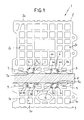
- The description of some preferred but not exclusive embodiments of an insulating enbloc for buildings according to the present invention is provided below, purely by way of non limiting indicative example, and illustrated in the accompanying drawings, wherein:
- Figure 1 is a partially sectioned plan view of an insulating enbloc for buildings according to a first embodiment;
- Figure 2 is a partially sectioned top view of the enbloc in accordance with a second embodiment;
- Figure 3 is a partially sectioned top view of the enbloc according to the present invention in accordance with a third embodiment;
- Figure 4 is a partially sectioned top view of the enbloc in accordance with a fourth embodiment;
- Figures 5 through 10 are sectioned views of a series of phases of a preferential method
for fastening mechanical attachment elements to an insulating body of the enbloc.
With reference to the aforementioned figures, the
number 1 indicates in its entirety an enbloc for buildings in accordance with the present invention. - As Figures 1 through 4 show, the
enbloc 1 comprises afirst block 2 preferably made of clay presenting a plurality of lightening throughopenings 2a oriented vertically. Theenbloc 1 further comprises asecond block 3 engaged to thefirst block 2, also preferably made of clay and presenting a series of lightening throughopenings 3a. - The first and the
second block insulating body 4 which can be made of different materials depending on the technical requirements to be met. In particular, for the rigid engagement of thefirst block 2 and of thesecond block 3 to theinsulating body 4 theenbloc 1 provides for the presence of at least a first and a secondmechanical coupling elements 5 fastened respectively in correspondence with opposite sides of theinsulating body 4. More specifically it is preferable for eachblock body 4 by means of at least twomechanical coupling elements 5 appropriately distanced from each other. - Each
mechanical coupling element 5 presents at least anattachment portion 5a for fastening itself to theinsulating body 4 and at least acoupling portion 5b destined to engage at least arespective coupling seat 6 obtained in thecorresponding block - The rigid junction between each
mechanical coupling element 5 and theinsulating body 4 is secured by means of at least amechanical fastening element 7 operatively engaged between theinsulating body 4 and theattachment portion 5a of the mechanical fastening element itself. - In the embodiments illustrated in the accompanying figures, each
mechanical fastening element 7 is set to make fast, with respect to theinsulating body 4, in correspondence with opposite sides thereof, twomechanical coupling elements 5. More specifically, eachmechanical fastening element 7 extends through theinsulating body 4 and presents a first and asecond extremity mechanical coupling elements 5 with respect to theinsulating body 4. - It is also possible, depending on the requirements, for the mechanical,
coupling element 5 not to be fastened to theinsulating body 4 in pairs, but to be individually fastened thereto. In this situation, anextremity mechanical fastening element 7 retains, with respect to theinsulating body 4, the respectivemechanical coupling element 5, whereas theother extremity insulating body 4, with the possible interposition of a rigid plate or the like. - Preferably, each
mechanical coupling element 5 is rigidly associated to theinsulating body 4 by means of twomechanical fastening elements 7 set parallel and mutually distanced in such a way as to prevent the fastening element from rotating in undesirable manners. - To ensure the correct and precise mutual distancing between the mechanical coupling elements,
tubular spacers 8 can be provided, each positioned around a respectivemechanical fastening element 7. - More specifically each
spacer 8 is co-axially inserted on the respectivemechanical fastening element 7 and presents a length substantially no lesser than the thickness of theinsulating body 4. - Each
spacer 8 further presents respectiveopposite extremities 8a in contact relationship with theattachment portions 5a of the respectivemechanical coupling elements 5. - Consequently, when the
mechanical coupling elements 5 are fastened to theinsulating body 4, themechanical coupling elements 5 are set directly against theextremities 8a of thespacer 8 without any risk of damaging theinsulating body 4 during the assembly phases effected to construct theenbloc 1. - It is also possible for each
spacer 8 associated to the respectivemechanical fastening element 7 to be realised in such a way as to have a length greater than the thickness of the insulating body 4 (see Figure 2). In this way it is possible to obtain between theinsulating body 4 and at least one of theblocks gap 9 for aeration and/or for inserting - as required - pipelines, electrical cables, or other elements into the wall to be built. - It should further be noted that the
gap 9 can be realised between the first block and theinsulating body 4 or, if necessary, twogaps 9 can be realised, respectively interposed between theblocks insulating body 4. - As shown in Figure 2, when the
enbloc 1 is provided with at least agap 9, at least a known securingelement 9a is externally engaged to eachspacer 8 to prevent theinsulating body 4 from sliding along the spacers themselves. More specifically, thesecuring elements 9a are engaged to thespacers 8 in correspondence with the side of theinsulating body 4 that faces thegap 9. When twogaps 9 are provided, on eachspacer 8 are engaged two securingelements 9a situated respectively against the opposite sides of theinsulating body 4. These securingelements 9a hold the insulating body fast with respect to the spacers themselves in the desired position. - Preferably, each
mechanical fastening element 7 comprises a rivet which is fastened to theinsulating body 4 and to the respectivemechanical coupling elements 5 according to a method which will be described farther on. - As Figures 1 and 2 show, each
mechanical coupling element 5 can comprise an elastically yielding deformed laminar element, whose coupling portion is defined bylateral tabs 5b converging symmetrically away from theattachment portion 5a, according to a substantially transverse orientation. Thelateral tabs 5b are provided with foldedback terminal portions 5c presenting for instance a rounded profile (Figure 1) or an acute angle profile (Figure 2), set to engagerespective strike portions 6a obtained in thecoupling seat 6 substantially defined by a recess provided with receivingsurfaces 6b diverging externally with respect toblock insulating body 4. More in detail, when theinsulating body 4 is made fast to therespective block lateral tabs 5b of eachcoupling element 5 are elastically pressed against one another by sliding with interference on thereceiving surfaces 6b of thecoupling seat 6. When the terminal portions of thelateral tabs 5b reach thestrike portions 6a they snap elastically, engaging thestrike portions 6a as stated above. Once they have snapped, thelateral tabs 5b interact with thestrike portions 6a of therespective coupling seat 6 to hold the insulating body fast to therespective block - Figure 3 shows a third embodiment which provides for each
mechanical coupling element 5 to comprise a laminar element which may be rigid, set to be inserted by sliding into therespective coupling seat 6. - In this case, the coupling seat is shaped in the manner of a through groove with two
lateral surfaces 6b converging externally to therespective block body 4, to form an undercut in the coupling seat itself. - Each rigid laminar element presents as a
coupling portion 5b interference tabs which diverge symmetrically away from theattachment portion 5a according to a substantially transverse orientation with respect thereto. The insulatingbody 4 is made fast to therespective blocks laminar elements 5 into the correspondingcoupling seats 6, determining a relative sliding between the insulatingbody 4 and the blocks themselves on the plane of their sides that face each other. - Figure 4 shows a fourth embodiment wherein each
mechanical coupling element 5 comprises a laminar element, elastically yielding, presentinglateral tabs 5b extending symmetrically from theattachment portion 5a and provided with respectiveterminal appendices 5c substantially oriented one towards the other. In this solution, thecoupling seats 6 comprise coupling projections 6c destined operatively to engage the respectivelaminar element 5. - In detail, when the insulating
body 4 is made fast to therespective block lateral tabs 5b of the respectivelaminar elements 5 spreading the lateral tabs themselves. - Subsequently, such
lateral tabs 5b are coupled by snapping inappropriate cavities 6b obtained on the coupling projection 6c securing the junction between the insulatingbody 4 and therespective block - The realisation of the insulating
enbloc 1 requires first the formation of the first andsecond block body 4. - The insulating
body 4, formed as a distinct, separate element from theblocks - Advantageously, a plurality of insulating
bodies 4 can be obtained by a simple cutting or die-cutting operation of a single previously formed panel. - The
mechanical coupling elements 5 and themechanical fastening elements 7 are also realised separately from the insulatingbody 4 and from theblocks - The insulating
body 4 is readied for assembly with theblocks mechanical coupling elements 5 on the opposite sides of the insulating body itself. - For purposes of fastening each
mechanical coupling element 5, it is preferably provided for the rivets or equivalentmechanical fastening elements 7 to be first fitted onto respective centring stems 10 set on an assembling apparatus. A firstmechanical coupling element 5 is then engaged on therivets 7 in such a way that each of the rivets is inserted in a through hole obtained in theattachment portion 5a of the coupling element itself, bringing itshead 7a in contact relationship with the aforesaid attachment portion, as per Figure 6. - Subsequently, on each
rivet 7 is fitted the respectivetubular spacer 8, in such a way that astrike extremity 8a thereof is positioned in contact against theattachment portion 5a on the side opposite to thehead 7a of therivet 7, as per Figure 6. - The insulating
body 4 is then fitted onto thespacer 8 in such a way as to determine its engagement with therivets 7 and themechanical coupling element 5. More specifically, in this phase eachrivet 7 with therespective spacer 8 are inserted in a through hole provided in the insulatingbody 4, as per Figure 7. - Alternatively, the
spacers 8 can first be inserted through the insulatingbody 4, then fitted onto therivets 7 together with the insulating body itself. - As Figure 8 shows, the
second coupling element 5 is then engaged on the insulatingbody 4, causing the insertion of thesecond extremity 7b of eachrivet 7 through theattachment portion 5a of the coupling element itself. - A terminal edge of the
second extremity 7b of eachrivet 7, opposite to thefirst coupling element 5 is then folded back, to determine the definitive fastening of thecoupling element 5 to the insulatingbody 4. - This phase can be implemented, for instance, using a cold-forming punch towards an insulating
body 4 to determine the plastic deformation of thesecond extremity 7b of therivet 7. In this circumstance, the presence of thespacers 8 eliminates the risk that the structure of the insulatingbody 4 may collapse as an effect of the thrusts transmitted to themechanical coupling elements 5, with consequent partial sinking thereof into the surface of the insulating body itself. - In a preferential embodiment, however, at least one
mill 11 is used, presenting aconical working portion 11a, eccentric with respect to the axis of rotation of the mill itself. The eccentric rotation of the conical workingportion 11a determines the terminal portion of therivet 7 to be bent as a result of the axial approach of themill 11 towards the rivet itself, as clearly visible in Figures 9 and 10, without transmitting relevant thrust actions on themechanical coupling elements 5. - Once the
mechanical coupling elements 5 are completely made fast to the insulatingbody 4, the latter is removed from the centring stems 10, proceeding to engage the first and thesecond block - For this purpose, with reference to the embodiments illustrated in Figures 1, 2 and 4, the insulating
body 4 is interposed between theblocks attachment portions 5a of thecoupling elements 5 situated to the opposite sides of the insulatingbody 4. Theblocks body 4, determining the snapping engagement of thelateral tabs 5b into the respective coupling seats 6. In this phase as well, the presence of thespacers 8 is useful in protecting the insulatingbody 4 against excessive stresses, eliminating all risks of penetration by themechanical coupling elements 5 into the surface of the insulating body itself which would compromise the correct engagement of the coupling elements in therespective seats 6. - With reference to the embodiment of Figure 3, the
blocks body 4, i.e. to the distance measurable between theattachment portions 5a of thecoupling elements 5. - The insulating
body 4 is then inserted between theblocks coupling elements 5 in therespective seats 6. - As is readily apparent from the above description, the engagement of the
blocks body 4 is preferably effected simultaneously in a single phase, but the possibility of determining the engagement of theindividual blocks 3 in successive phases is not excluded. - The present invention attains important advantages.
- In particular, the invention brings about considerable improvements in relation to the time required to produce the enblocs. In this regard it should be noted that the subject method does not call for productive phases that require long waiting times for the realisation of the insulating phase. All the phases of the assembly of the enbloc can instead be executed in an extremely simple and fast manner.
- In other words, making available an insulating enbloc whose components are made independently from each other and then assembled at a later time by means of extremely simple operations entails considerable advantages in terms of economy and flexibility of the productive cycles, as well as in terms of investment cost for the production facilities.
- It is advantageously possible to prepare different types of insulating
body 4, for instance of different materials and/or thickness, already provided with the respective coupling elements. The capability is thereby achieved of replacing in a nearly immediate manner the type of insulating body to be used to realise different enbloc types, in order to meet even requirements for the delivery of small batches. - It should further be noted that the invention allows to provide an aeration gap inside the enbloc, which could not be achieved in the prior art, where the insulating layer was formed directly by filling the space defined between the blocks positioned one in front of the other.
Claims (24)
- Method for the realisation of an insulating enbloc for buildings comprising the following phases:realising a first block (2);realising a second block (3);interposing an insulating body (4) between the first block (2) and the second block (3), characterised in that the interposition of the insulating body (4) between the blocks (2, 3) calls for the following phases:forming the insulating body (4);positioning the previously formed insulating body (4) between the first and the second block (2, 3);engaging the first and the second block (2, 3) to the insulating body (4) by means of mechanical coupling elements (5).
- Method according to claim 1, wherein the engagement of the first and of the second block (2, 3) to the insulating body (4) comprises the following phases:associating at least a mechanical coupling element (5) to the insulating body (4) on each side thereof;engaging each block (2, 3) to the respective mechanical coupling element (5).
- Method according to claim 2, wherein the engagement of the blocks (2, 3) to the respective mechanical coupling elements (5) is achieved by forcibly approaching the blocks (2, 3) to the insulating body (4).
- Method according to claim 3, wherein the engagement of the blocks (2, 3) to the respective mechanical coupling elements (5) is achieved by means of relative sliding between each block (2, 3) and the insulating body (4) in the plane of the sides bearing the mechanical coupling elements (5).
- Method according to claims 3 or 4, wherein the engagement of the first and of the second block (2, 3) to the respective mechanical coupling elements (5) is performed simultaneously.
- Method according to claim 2, wherein the association of each mechanical coupling element (5) to the insulating body (4) takes place by means of at least a mechanical fastening element (7).
- Method according to claim 2, wherein the association of each mechanical coupling element (5) to the insulating body (4) takes place by means of riveting.
- Method according to claim 7, wherein the riveting process is carried out by means of the following phase:inserting at least a rivet (7) into a through hole of a first mechanical coupling element (5);inserting said rivet (7) in a through hole of the insulating body (4);folding back a terminal edge of the rivet (7) to the opposite side from the first coupling element (5) to make the latter fast to the insulating body (4).
- Method according to claim 8, wherein before the phase of inserting the rivet (7) into the through hole of the insulating body (4) at least a spacer (8) is fitted onto the rivet (7), said spacer (8) having an axial dimension that is at least equal to the thickness of the insulating body (4).
- Method according to claim 8, wherein before the folding-back phase the rivet (7) is inserted into a through hole of a second mechanical coupling element (5).
- Method according to claim 8, wherein said folding back phase of the terminal edge of the rivet (7) is accomplished by means of a mill (11) presenting a conical portion (11a) eccentric with respect to the axis of rotation of the mill (11), the latter operating on the terminal edge of the rivet (7) in such a way that its conical portion (11a) folds the terminal edge of the rivet (7).
- Insulating enbloc for buildings obtained with a method according to one or more of the previous claims.
- Insulating enbloc for buildings comprising:a first block (2);a second block (3);at least an insulating body (4) interposed between the first block (2) and the second block (3), characterised in that it further comprises:at least a mechanical coupling element (5) presenting at least an attachment portion (5a) for its own fastening to the insulating body (4) and at least a coupling portion (5b) destined to engage at least a respective coupling seat (6) obtained in one of said blocks (2, 3);at least a mechanical coupling element (7) operatively engaged between the insulating body (4) and said attachment portion (5a) to fasten rigidly said at least a mechanical coupling element (5) to the insulating body itself.
- Enbloc according to claim 13, characterised in that it comprises at least a first and a second mechanical coupling element (2, 3) engaged respectively in correspondence with opposite sides of the insulating body (4) to fasten the first and the second block (2, 3) to the insulating body itself.
- Enbloc according to claim 14, characterised in that said at least one mechanical fastening element (7) extends through the insulating body (4) and presents a first and a second extremity (7a, 7b) which retain respectively the first and the second coupling elements (5) with respect to the insulating body itself.
- Enbloc according to claim 14, characterised in that it further comprises at least a tubular spacer (8) positioned around said fastening element (7).
- Enbloc according to claim 16, characterised in that said spacer (8) presents a length substantially equal to the thickness of the insulating element (4).
- Enbloc according to claim 16, characterised in that said spacer (8) presents a length greater than the thickness of the insulating element (4).
- Enbloc according to claim 16, characterised in that the spacer (8) presents respective opposite extremities (8a) in contact relationship with the attachment portions (5a) of a first and a second mechanical coupling elements (2,3 ) engaged respectively in correspondence with opposite sides of the insulating body (4).
- Enbloc according to claim 13, characterised in that said mechanical fastening element (7) comprises at least a rivet.
- Enbloc according to claim 13, characterised in that for each mechanical coupling element (5) at least two mechanical fastening elements 7 are provided.
- Enbloc according to claim 13, characterised in that said at least one mechanical coupling element (5) is realised separately from the insulating body (4) and joined thereto by means of said at least an element.
- Enbloc according to claim 13, wherein each mechanical coupling element (5) comprises at least an elastically yielding laminar element able to be engaged by snapping into the respective coupling seat (6) of the corresponding block (2, 3), said coupling portion comprising at least a pair of lateral tabs (5b) presenting respective folded back terminal portions (5c) set to engage respective undercuts obtained in the coupling seat (6).
- Enbloc according to claim 13, wherein each mechanical coupling element (5) comprises at least a rigid laminar element destined to be inserted by sliding into the respective coupling seat (6), said coupling portion comprising at least a pair of interference tabs (5b) able to be inserted by sliding into said coupling seat (6), shaped in the manner of a through groove.
Priority Applications (4)
| Application Number | Priority Date | Filing Date | Title |
|---|---|---|---|
| DE69900609T DE69900609T2 (en) | 1999-09-08 | 1999-09-08 | Insulating building block |
| EP99830558A EP1085137B1 (en) | 1999-09-08 | 1999-09-08 | An insulating enbloc for buildings |
| ES99830558T ES2167997T3 (en) | 1999-09-08 | 1999-09-08 | AN INSULATING BLOCK FOR BUILDINGS. |
| AT99830558T ATE210772T1 (en) | 1999-09-08 | 1999-09-08 | HEAT-INSULATING CONSTRUCTION BLOCK |
Applications Claiming Priority (1)
| Application Number | Priority Date | Filing Date | Title |
|---|---|---|---|
| EP99830558A EP1085137B1 (en) | 1999-09-08 | 1999-09-08 | An insulating enbloc for buildings |
Publications (2)
| Publication Number | Publication Date |
|---|---|
| EP1085137A1 true EP1085137A1 (en) | 2001-03-21 |
| EP1085137B1 EP1085137B1 (en) | 2001-12-12 |
Family
ID=8243573
Family Applications (1)
| Application Number | Title | Priority Date | Filing Date |
|---|---|---|---|
| EP99830558A Expired - Lifetime EP1085137B1 (en) | 1999-09-08 | 1999-09-08 | An insulating enbloc for buildings |
Country Status (4)
| Country | Link |
|---|---|
| EP (1) | EP1085137B1 (en) |
| AT (1) | ATE210772T1 (en) |
| DE (1) | DE69900609T2 (en) |
| ES (1) | ES2167997T3 (en) |
Cited By (7)
| Publication number | Priority date | Publication date | Assignee | Title |
|---|---|---|---|---|
| WO2004072400A1 (en) * | 2003-02-17 | 2004-08-26 | Perez Aranda Carlos | Multi-purpose integrated thermoacoustic brickwork |
| EP1876309A1 (en) * | 2006-07-06 | 2008-01-09 | Stamford Consulting Limited | Block assembly for buildings and relevant manufacturing method |
| EP2072839A1 (en) | 2007-12-21 | 2009-06-24 | Marco Tarello | Proceeding for manufacturing an insulating building product for buildings and building product thereby obtained |
| EP2116663A1 (en) | 2008-05-08 | 2009-11-11 | Stamford Consulting Limited | Insulating composite block for the building industry, and method of manufacturing said block |
| ITRI20080008A1 (en) * | 2008-09-08 | 2010-03-09 | Bartolini Mario | PRE-PACKAGING BLOCK FOR STRUCTURE OF REINFORCED CONCRETE STRUCTURES IN RESPECT OF NEW LEGISLATIVE PROVISIONS ON ENERGY CONTAINMENT AND SAFETY ON THE CONSTRUCTION SITE WITH MATERIALS AND TECHNOLOGIES AT LOW ENVIRONMENTAL IMPACT |
| ITTV20100037A1 (en) * | 2010-03-18 | 2011-09-19 | Roberto Bampo | BRICK WALLED BRICKWORK AND BRICKWORK FOR THE CONSTRUCTION OF SUCH WALLS |
| IT201700028493A1 (en) * | 2017-03-15 | 2018-09-15 | Salvatore Vinci | CONSTRUCTION ELEMENT FOR MASONRY SUPPLIED WITH INTERMEDIATE PANEL IN THERMAL AND ACOUSTIC INSULATING MATERIAL |
Citations (2)
| Publication number | Priority date | Publication date | Assignee | Title |
|---|---|---|---|---|
| EP0041417A1 (en) * | 1980-05-29 | 1981-12-09 | Centre D'etudes Et De Recherches De L'industrie Du Beton Manufacture | Building block with insulating material incorporated therein for exterior insulation |
| DE8809461U1 (en) * | 1988-07-25 | 1988-10-27 | Schröter, Ruprecht, 3000 Hannover | Kit for producing a brick insulation facade |
-
1999
- 1999-09-08 ES ES99830558T patent/ES2167997T3/en not_active Expired - Lifetime
- 1999-09-08 DE DE69900609T patent/DE69900609T2/en not_active Expired - Lifetime
- 1999-09-08 AT AT99830558T patent/ATE210772T1/en active
- 1999-09-08 EP EP99830558A patent/EP1085137B1/en not_active Expired - Lifetime
Patent Citations (2)
| Publication number | Priority date | Publication date | Assignee | Title |
|---|---|---|---|---|
| EP0041417A1 (en) * | 1980-05-29 | 1981-12-09 | Centre D'etudes Et De Recherches De L'industrie Du Beton Manufacture | Building block with insulating material incorporated therein for exterior insulation |
| DE8809461U1 (en) * | 1988-07-25 | 1988-10-27 | Schröter, Ruprecht, 3000 Hannover | Kit for producing a brick insulation facade |
Cited By (8)
| Publication number | Priority date | Publication date | Assignee | Title |
|---|---|---|---|---|
| WO2004072400A1 (en) * | 2003-02-17 | 2004-08-26 | Perez Aranda Carlos | Multi-purpose integrated thermoacoustic brickwork |
| EP1876309A1 (en) * | 2006-07-06 | 2008-01-09 | Stamford Consulting Limited | Block assembly for buildings and relevant manufacturing method |
| EP2072839A1 (en) | 2007-12-21 | 2009-06-24 | Marco Tarello | Proceeding for manufacturing an insulating building product for buildings and building product thereby obtained |
| EP2116663A1 (en) | 2008-05-08 | 2009-11-11 | Stamford Consulting Limited | Insulating composite block for the building industry, and method of manufacturing said block |
| ITRI20080008A1 (en) * | 2008-09-08 | 2010-03-09 | Bartolini Mario | PRE-PACKAGING BLOCK FOR STRUCTURE OF REINFORCED CONCRETE STRUCTURES IN RESPECT OF NEW LEGISLATIVE PROVISIONS ON ENERGY CONTAINMENT AND SAFETY ON THE CONSTRUCTION SITE WITH MATERIALS AND TECHNOLOGIES AT LOW ENVIRONMENTAL IMPACT |
| ITTV20100037A1 (en) * | 2010-03-18 | 2011-09-19 | Roberto Bampo | BRICK WALLED BRICKWORK AND BRICKWORK FOR THE CONSTRUCTION OF SUCH WALLS |
| IT201700028493A1 (en) * | 2017-03-15 | 2018-09-15 | Salvatore Vinci | CONSTRUCTION ELEMENT FOR MASONRY SUPPLIED WITH INTERMEDIATE PANEL IN THERMAL AND ACOUSTIC INSULATING MATERIAL |
| EP3375583A1 (en) * | 2017-03-15 | 2018-09-19 | Salvatore Vinci | Masonry building element provided with intermediate panel made of thermally insulated and sound absorbing material |
Also Published As
| Publication number | Publication date |
|---|---|
| EP1085137B1 (en) | 2001-12-12 |
| ES2167997T3 (en) | 2002-05-16 |
| ATE210772T1 (en) | 2001-12-15 |
| DE69900609D1 (en) | 2002-01-24 |
| DE69900609T2 (en) | 2002-06-13 |
Similar Documents
| Publication | Publication Date | Title |
|---|---|---|
| US6889479B2 (en) | Building block | |
| CA2298435E (en) | Insulating concrete form system | |
| EP1085137B1 (en) | An insulating enbloc for buildings | |
| US7182545B2 (en) | Structural element for a motor vehicle comprising two metal members and a reinforcing piece of plastics material which brings about the connection of the members, and a corresponding motor vehicle | |
| CA2551892A1 (en) | Bonded siding panels | |
| EP1907650B1 (en) | Metal finishing tile, production method and related covering | |
| KR101763540B1 (en) | Modular insulation assembly using sandwich panel and Construction Method thereof | |
| KR100468282B1 (en) | Reinforced concrete structure using mold body joining type concrete form using dividable spacer member, method of manufacturing same, and form material | |
| KR20150078231A (en) | Panel for building | |
| CN101769057B (en) | Roof board unit structure of lightweight house | |
| KR101673119B1 (en) | Method for manufacturing partition panel and round type partition using the same | |
| CN109594734B (en) | Wall panel mounting device and method | |
| JPH08158506A (en) | Ceramics block and manufacture thereof and ceramics block wall | |
| JP3706476B2 (en) | Spacing member and mold forming member including the same | |
| KR200375683Y1 (en) | Tile base | |
| US7833460B2 (en) | Rotational molding method | |
| CN215631233U (en) | Building block type composite wall board | |
| KR20170047087A (en) | The panel for wall of a set building and thereof construction method | |
| JP2002347055A (en) | Automotive cavity sealing material | |
| JPH0435456Y2 (en) | ||
| KR102322112B1 (en) | deformed wire mesh integrated insulation panel and manufacturing method thereof | |
| KR101661083B1 (en) | Prefabricated panal | |
| JPH11323955A (en) | Separator for form and concrete placing form using this separator | |
| CN116446568B (en) | A ceramic brick hanging system | |
| JPH06207441A (en) | Construction panel body and jointing method therefor |
Legal Events
| Date | Code | Title | Description |
|---|---|---|---|
| PUAI | Public reference made under article 153(3) epc to a published international application that has entered the european phase |
Free format text: ORIGINAL CODE: 0009012 |
|
| GRAG | Despatch of communication of intention to grant |
Free format text: ORIGINAL CODE: EPIDOS AGRA |
|
| GRAG | Despatch of communication of intention to grant |
Free format text: ORIGINAL CODE: EPIDOS AGRA |
|
| GRAH | Despatch of communication of intention to grant a patent |
Free format text: ORIGINAL CODE: EPIDOS IGRA |
|
| 17P | Request for examination filed |
Effective date: 20000225 |
|
| AK | Designated contracting states |
Kind code of ref document: A1 Designated state(s): AT CH DE ES FR IT LI |
|
| AX | Request for extension of the european patent |
Free format text: AL;LT;LV;MK;RO;SI |
|
| GRAH | Despatch of communication of intention to grant a patent |
Free format text: ORIGINAL CODE: EPIDOS IGRA |
|
| GRAA | (expected) grant |
Free format text: ORIGINAL CODE: 0009210 |
|
| AK | Designated contracting states |
Kind code of ref document: B1 Designated state(s): AT CH DE ES FR IT LI |
|
| AKX | Designation fees paid |
Free format text: AT CH DE ES FR IT LI |
|
| AX | Request for extension of the european patent |
Free format text: AL;LT;LV;MK;RO;SI |
|
| REF | Corresponds to: |
Ref document number: 210772 Country of ref document: AT Date of ref document: 20011215 Kind code of ref document: T |
|
| REG | Reference to a national code |
Ref country code: CH Ref legal event code: NV Representative=s name: ISLER & PEDRAZZINI AG Ref country code: CH Ref legal event code: EP |
|
| REG | Reference to a national code |
Ref country code: IE Ref legal event code: FG4D |
|
| REF | Corresponds to: |
Ref document number: 69900609 Country of ref document: DE Date of ref document: 20020124 |
|
| ET | Fr: translation filed | ||
| REG | Reference to a national code |
Ref country code: ES Ref legal event code: FG2A Ref document number: 2167997 Country of ref document: ES Kind code of ref document: T3 |
|
| PLBE | No opposition filed within time limit |
Free format text: ORIGINAL CODE: 0009261 |
|
| STAA | Information on the status of an ep patent application or granted ep patent |
Free format text: STATUS: NO OPPOSITION FILED WITHIN TIME LIMIT |
|
| 26N | No opposition filed | ||
| REG | Reference to a national code |
Ref country code: IE Ref legal event code: MM4A |
|
| REG | Reference to a national code |
Ref country code: CH Ref legal event code: PCAR Free format text: ISLER & PEDRAZZINI AG;POSTFACH 1772;8027 ZUERICH (CH) |
|
| PGFP | Annual fee paid to national office [announced via postgrant information from national office to epo] |
Ref country code: DE Payment date: 20121130 Year of fee payment: 14 |
|
| PGFP | Annual fee paid to national office [announced via postgrant information from national office to epo] |
Ref country code: AT Payment date: 20121002 Year of fee payment: 14 |
|
| PGFP | Annual fee paid to national office [announced via postgrant information from national office to epo] |
Ref country code: CH Payment date: 20130925 Year of fee payment: 15 |
|
| PGFP | Annual fee paid to national office [announced via postgrant information from national office to epo] |
Ref country code: FR Payment date: 20130927 Year of fee payment: 15 |
|
| PGFP | Annual fee paid to national office [announced via postgrant information from national office to epo] |
Ref country code: ES Payment date: 20131025 Year of fee payment: 15 |
|
| REG | Reference to a national code |
Ref country code: AT Ref legal event code: MM01 Ref document number: 210772 Country of ref document: AT Kind code of ref document: T Effective date: 20130908 |
|
| REG | Reference to a national code |
Ref country code: DE Ref legal event code: R119 Ref document number: 69900609 Country of ref document: DE Effective date: 20140401 |
|
| PG25 | Lapsed in a contracting state [announced via postgrant information from national office to epo] |
Ref country code: DE Free format text: LAPSE BECAUSE OF NON-PAYMENT OF DUE FEES Effective date: 20140401 Ref country code: AT Free format text: LAPSE BECAUSE OF NON-PAYMENT OF DUE FEES Effective date: 20130908 |
|
| REG | Reference to a national code |
Ref country code: CH Ref legal event code: PL |
|
| REG | Reference to a national code |
Ref country code: FR Ref legal event code: ST Effective date: 20150529 |
|
| PG25 | Lapsed in a contracting state [announced via postgrant information from national office to epo] |
Ref country code: CH Free format text: LAPSE BECAUSE OF NON-PAYMENT OF DUE FEES Effective date: 20140930 Ref country code: LI Free format text: LAPSE BECAUSE OF NON-PAYMENT OF DUE FEES Effective date: 20140930 |
|
| PG25 | Lapsed in a contracting state [announced via postgrant information from national office to epo] |
Ref country code: FR Free format text: LAPSE BECAUSE OF NON-PAYMENT OF DUE FEES Effective date: 20140930 |
|
| REG | Reference to a national code |
Ref country code: ES Ref legal event code: FD2A Effective date: 20151026 |
|
| PG25 | Lapsed in a contracting state [announced via postgrant information from national office to epo] |
Ref country code: ES Free format text: LAPSE BECAUSE OF NON-PAYMENT OF DUE FEES Effective date: 20140909 |
|
| PGFP | Annual fee paid to national office [announced via postgrant information from national office to epo] |
Ref country code: IT Payment date: 20180221 Year of fee payment: 19 |
|
| PG25 | Lapsed in a contracting state [announced via postgrant information from national office to epo] |
Ref country code: IT Free format text: LAPSE BECAUSE OF NON-PAYMENT OF DUE FEES Effective date: 20180908 |