EP1084936A2 - Vehicle body structure - Google Patents
Vehicle body structure Download PDFInfo
- Publication number
- EP1084936A2 EP1084936A2 EP00307893A EP00307893A EP1084936A2 EP 1084936 A2 EP1084936 A2 EP 1084936A2 EP 00307893 A EP00307893 A EP 00307893A EP 00307893 A EP00307893 A EP 00307893A EP 1084936 A2 EP1084936 A2 EP 1084936A2
- Authority
- EP
- European Patent Office
- Prior art keywords
- pillar
- box
- air
- hood ridge
- rising wall
- Prior art date
- Legal status (The legal status is an assumption and is not a legal conclusion. Google has not performed a legal analysis and makes no representation as to the accuracy of the status listed.)
- Granted
Links
- 229910052751 metal Inorganic materials 0.000 claims description 16
- 239000002184 metal Substances 0.000 claims description 16
- 239000000463 material Substances 0.000 claims description 7
- 230000000630 rising effect Effects 0.000 claims 18
- 238000005058 metal casting Methods 0.000 claims 2
- 239000000725 suspension Substances 0.000 abstract description 18
- 238000005452 bending Methods 0.000 description 6
- 238000005266 casting Methods 0.000 description 6
- 230000005540 biological transmission Effects 0.000 description 5
- 238000003466 welding Methods 0.000 description 5
- 150000002739 metals Chemical class 0.000 description 4
- 229910000838 Al alloy Inorganic materials 0.000 description 3
- 229910000861 Mg alloy Inorganic materials 0.000 description 3
- 239000000470 constituent Substances 0.000 description 3
- -1 for example Inorganic materials 0.000 description 3
- 230000004048 modification Effects 0.000 description 2
- 238000012986 modification Methods 0.000 description 2
- 238000000465 moulding Methods 0.000 description 2
- 230000015572 biosynthetic process Effects 0.000 description 1
- 238000001125 extrusion Methods 0.000 description 1
- 230000010354 integration Effects 0.000 description 1
- 238000004519 manufacturing process Methods 0.000 description 1
- 230000002787 reinforcement Effects 0.000 description 1
- 238000000926 separation method Methods 0.000 description 1
Images




Classifications
-
- C—CHEMISTRY; METALLURGY
- C09—DYES; PAINTS; POLISHES; NATURAL RESINS; ADHESIVES; COMPOSITIONS NOT OTHERWISE PROVIDED FOR; APPLICATIONS OF MATERIALS NOT OTHERWISE PROVIDED FOR
- C09D—COATING COMPOSITIONS, e.g. PAINTS, VARNISHES OR LACQUERS; FILLING PASTES; CHEMICAL PAINT OR INK REMOVERS; INKS; CORRECTING FLUIDS; WOODSTAINS; PASTES OR SOLIDS FOR COLOURING OR PRINTING; USE OF MATERIALS THEREFOR
- C09D11/00—Inks
- C09D11/30—Inkjet printing inks
- C09D11/32—Inkjet printing inks characterised by colouring agents
- C09D11/324—Inkjet printing inks characterised by colouring agents containing carbon black
-
- B—PERFORMING OPERATIONS; TRANSPORTING
- B62—LAND VEHICLES FOR TRAVELLING OTHERWISE THAN ON RAILS
- B62D—MOTOR VEHICLES; TRAILERS
- B62D25/00—Superstructure or monocoque structure sub-units; Parts or details thereof not otherwise provided for
- B62D25/04—Door pillars ; windshield pillars
-
- B—PERFORMING OPERATIONS; TRANSPORTING
- B62—LAND VEHICLES FOR TRAVELLING OTHERWISE THAN ON RAILS
- B62D—MOTOR VEHICLES; TRAILERS
- B62D25/00—Superstructure or monocoque structure sub-units; Parts or details thereof not otherwise provided for
- B62D25/08—Front or rear portions
- B62D25/081—Cowls
-
- C—CHEMISTRY; METALLURGY
- C09—DYES; PAINTS; POLISHES; NATURAL RESINS; ADHESIVES; COMPOSITIONS NOT OTHERWISE PROVIDED FOR; APPLICATIONS OF MATERIALS NOT OTHERWISE PROVIDED FOR
- C09D—COATING COMPOSITIONS, e.g. PAINTS, VARNISHES OR LACQUERS; FILLING PASTES; CHEMICAL PAINT OR INK REMOVERS; INKS; CORRECTING FLUIDS; WOODSTAINS; PASTES OR SOLIDS FOR COLOURING OR PRINTING; USE OF MATERIALS THEREFOR
- C09D11/00—Inks
- C09D11/30—Inkjet printing inks
- C09D11/38—Inkjet printing inks characterised by non-macromolecular additives other than solvents, pigments or dyes
-
- C—CHEMISTRY; METALLURGY
- C09—DYES; PAINTS; POLISHES; NATURAL RESINS; ADHESIVES; COMPOSITIONS NOT OTHERWISE PROVIDED FOR; APPLICATIONS OF MATERIALS NOT OTHERWISE PROVIDED FOR
- C09D—COATING COMPOSITIONS, e.g. PAINTS, VARNISHES OR LACQUERS; FILLING PASTES; CHEMICAL PAINT OR INK REMOVERS; INKS; CORRECTING FLUIDS; WOODSTAINS; PASTES OR SOLIDS FOR COLOURING OR PRINTING; USE OF MATERIALS THEREFOR
- C09D11/00—Inks
- C09D11/30—Inkjet printing inks
- C09D11/40—Ink-sets specially adapted for multi-colour inkjet printing
Definitions
- the present invention relates to a vehicle body structure. More particularly, it relates to the body structure in the circumference of an air box of the vehicle body.
- Japanese Patent Publication (kokai) No. 6-329051 discloses one body structure where the air box is connected with both of a front pillar and a hood ridge on one side of the vehicle body.
- the air box is arranged so as to extend along the direction of a vehicle's width, forming an automotive framework member.
- the above front pillar is arranged on each end of the air box in the vehicle's width direction.
- Each front pillar is arranged to extend along the upward-and-downward direction of the vehicle body, also forming one automotive framework member.
- the hood ridge is arranged on each side of the vehicle body, in its front section. On each side of the vehicle body, the hood ridge is arranged to extend along the fore-and-aft direction of the vehicle body, also forming one automotive framework member.
- the air box is provided, on each side in the width direction, with a horizontal flange.
- the hood ridge has a joint surface defined for integration with the air box.
- the above horizontal flange of the air box is piled on the joint surface defined on the hood ridge.
- the flange is connected to the joint surface by welding.
- the hood ridge has a lateral flange formed to project from its sidewall sideways.
- the front pillar has a flange formed to project from its sidewall sideways, for abutment with the lateral flange of the hood ridge.
- the lateral flange of the hood ridge is butted against the flange of the front pillar and successively welded to the same flange into one body.
- the above-mentioned body structure has a problem to be solved. That is, if an external force via an automotive suspension in the upward-and-downward direction, so-called “suspension input" is applied on the hood ridge, the resultant bending of the hood ridge allows a force to act on the above connections between the air box and the hood ridge and between the hood ridge and the front pillar in a direction to separate the horizontal flange of the air box from the joint surface of the hood ridge and separate the lateral flange of the hood ridge from the flange of the front pillar.
- a vehicle body which is made of a casting of light metal, for example, aluminum alloy, magnesium alloy, etc.
- a vehicle body structure comprising:
- the front-pillar inner member has a pillar-inner vertical wall formed generally along the fore-and-aft direction of the vehicle, an air-box socket formed inside the pillar-inner vertical wall in the width direction to receive the air box from its underside, and an air-box joint flange formed on the upper part of the front-pillar inner member to join it to the air box.
- the upper hood ridge member has a fore-and-aft-directional vertical wall formed with an opening for joint so as to extend in the fore-and-aft direction and also along the pillar-inner vertical wall's surface being outside in the direction of the vehicle's width, and a width-directional vertical wall formed at a rear part of the upper hood ridge member to extend along the direction of the vehicle's width.
- the front-pillar outer member has a notch formed for engagement with the rear part of the upper hood ridge member.
- the air box is provided with a flange to be joined to the air-box socket of the front-pillar inner member and a joint surface to be piled on the air-box joint flange. In the structure, the air box, the front-pillar inner members, the front-pillar outer members and the hood ridges are joined together.
- FIGS 1 to 7 illustrate the first embodiment of the present invention.
- Fig. 1 illustrates a vehicle body VB equipped with a body structure in accordance with an embodiment of the invention.
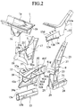
- Fig. 2 is an exploded perspective view of the body structure in the circumference of an air box in the vehicle body VB.
- the vehicle body structure mainly comprises an air box 1, an inner member 7 to be joined to the air box 1 to form a front pillar, an outer member 9 also forming the front pillar together with the inner member 7, and a hood ridge 11 to be joined to the outer member 9 and the inner member 7.
- the inner member 7 and the outer member 9 will be referred as "front-pillar inner member 7" and "front-pillar outer member 9", respectively
- Reference numeral 13 designates a roof structure to be joined to the front-pillar outer member 9.
- Reference numeral 15 denotes a front side member to be connected with the hood ridge 11. As shown in Fig. 1, the above constituents of the vehicle body structure and the front side member 15 are arranged on each side of the vehicle body VB in a direction of the body's width, beside the air box 1. Therefore, although the vehicle body VB is provided, on both sides thereof, with two body structure, the embodiment of the invention will be described with reference to one body structure on one side of the vehicle body VB. Note that both front ends of the front side members 15 are respectively connected to a cross member 2 which extends in the direction of the body's width. This direction will be referred as "vehicle's width direction", below.
- the front-pillar inner member 7, the front-pillar outer member 9, and the hood ridge 11 are made of castings of light metal, for example, aluminum alloy, magnesium alloy, etc.
- the air box 1 may be made from plate materials of the same light metal.
- the roof structure 13 is made of a casting of the same light metal.
- the front side member 15 is made of an extrusion of the same light metal. In this way, since the whole vehicle body is made of the light metal, the light-weightiness can be progressed from a point of view of materials remarkably.
- the air box 1 which is a framework member disposed in the vehicle's width direction, has a wall 1a formed to extend along the above direction.
- a horizontal flange 1b is formed to project from the end of the box 1 laterally.
- the horizontal flange 1b is provided, on its under-side, with a joint surface with the front-pillar inner member 7.
- a vertical flange 1c is formed so as to project further downward.
- the front-pillar inner member 7 has a "pillar-inner" vertical wall 17a formed to extend along a fore-and-aft direction of the vehicle. Inside the vertical wall 17a in the vehicle's width direction, an "air-box" socket 19 for receiving the air box 1 is formed to project inward of the vehicle's width direction.
- the air-box socket 19 is provided with a socket part 19a in the form of a groove for receiving the flange 1c.
- At the top of the member 7, it has a flange 21 for connecting the member 7 with the air box 1. This flange 21 is formed so as to project outward of the vehicle's width direction while directing its joint surface 21a upward.
- the front-pillar outer member 9 has an upper part 23 and a lower part 25.
- the upper part 23 is formed to succeed the lower part 25 through an inflecting part 27, forming an inside structure of the vehicle body.
- a side sill 28 is formed to succeed the lower part 25.
- the lower part 25 generally comprises a front vertical wall 29 extending along the vehicle's width direction, a rear vertical wall 31 also extending along the vehicle's width direction,and an outer vertical wall 33 extending along the vehicle's fore-and-aft direction.
- the front vertical wall 29 is provided, on an upper part thereof, with a notch 35.
- the hood ridge 11 includes a suspension attachment member (part) 37, a housing member (part) 39,and a upper hood ridge member (part) 41, all of which are formed into one casing body of light metal.
- the hood ridge 11 of the embodiment allows the number of components to be reduced, thereby facilitating the production.
- the suspension attachment member 37 is an element to be attached to a suspension (not shown) allowing a wheel to carry the vehicle body VB.
- the suspension attachment member 37 is provided, at a top face thereof, with a suspension attachment hole 37a for attachment with the suspension.
- the housing member 39 has an upper portion joined to the suspension attachment member 37.
- the housing member 39 further includes a flange 39a formed on its lower portion, for connection with the front side member 15 which forms one of lower frameworks of the vehicle body VB.
- the upper hood ridge member 41 is integrally joined to an upper portion of the housing member 5 outside in the vehicle's width direction and also formed so as to lengthen in the vehicle's fore-and-aft direction, forming the framework of the vehicle body.
- the upper hood ridge member 41 comprises an upper wall 41a, a lower wall 41b, and a "fore-and-aft-directional" vertical wall 41c connecting the upper wall 41a with the lower wall 41b, providing a substantial U-shaped cross section.
- the lower wall 41b is formed somewhat longer than the upper wall 41a in the vehicle's width direction, thereby providing a joint flange 41d.
- the vertical wall 41c is provided with a joint opening 41e.
- the rear end of the upper hood ridge member 41 is blocked up with a "width-directional" vertical wall 41f extending along the vehicle's width direction.
- the vertical wall 41f has a joint flange 41g arranged outside of the vehicle's width direction.
- a vertical wall 41h is formed so as to extend along the vehicle's width direction.
- a plurality of reinforcement ribs 41i are formed so as to extend along the vehicle's width direction. These ribs 41i are provided to connect the upper wall 41a, the lower wall 41b, and also the vertical wall 41c with each other.
- the front side member 15 connected with the underside of the hood ridge 11 forms the lower framework of the vehicle body VB and extends along the vehicle's fore-and-aft direction, which is similar to the upper hood ridge member 41.
- a joint flange 15a is formed so as to project obliquely upward, but inward of the vehicle's width direction.
- the front side member 15 has a similarly-inclined joint surface 15b formed to succeed to the joint flange 15a.
- the roof structure 13 has a front-pillar outer part 13a formed to fit with an external face of the upper part 23 of the front-pillar outer member 9.
- This front-pillar outer part 13a also forms a panel that extends from the roof, along an external surface of a front pillar of the vehicle.
- This front-pillar outer part 13a is combined with the upper part 23 of the front-pillar outer member 9 so as to define one closed-sectional structure.
- the lower end of the roof structure 13 is further elongated to define a joint wall 13b.
- the joint wall has a vertical wall 13c, an upper flange 13d,and a lower flange 13e.
- Fig. 3 is a partially-omitted side view of the assembly.
- the air box 1, the front-pillar inner member 7, the front-pillar outer member 9, the hood ridge 11, the roof structure 13, and the front side member 15 are joined together.
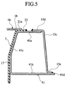
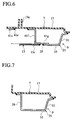
- Figs. 4 to 7 show respective sections of the above assembly. That is, Fig. 4 is a sectional view taken along a line A-A of Fig. 3.
- Fig. 5 is a sectional view taken along a line B-B and Fig. 6 a sectional view taken along a line C-C.
- Fig. 7 is a sectional view taken along a line D-D of Fig. 3.
- the rear part of the upper hood ridge member 41 is fitted into the notch 35 of the front-pillar outer member 9 and the vertical wall 41g is united with the outer vertical wall 33.
- the circumference of the notch 35 is welded to the vertical wall 41g, while the vertical wall 41g is welded to an inside face of the outer vertical wall 33.
- the lower vertical wall 41h is brought into surface contact with an inside face of the front vertical wall 29 and joined thereto by welding.
- the vertical wall 41f of the upper hood ridge member 41 occupies a position substantially identical to a position of the vertical wall 29 in the fore-and-aft direction of the vehicle.
- the vertical wall 41c of the upper hood-ridge part 41 is butted against the outer face of the vertical wall 17 of the front-pillar inner member 7. While, the joint flange 21 of the member 7 is joined to the upper wall's portion (41a) fallen a degree. In this state, the circumference of the opening 41e is welded to the vertical wall 17 and the joint flange 21 of the member 7 is welded to the upper wall 41a of the upper hood ridge member 41.
- the horizontal flange 1b of the air box 1 is piled on the joint surface 21a of the joint flange 21 and subsequently, the former is joined to the latter by welding.
- the other flange 1c of the air box 1 is inserted into the groove 19a of the socket 19 of the member 7 and joined thereto by adhering.
- an area 43 shown with doubly-slanted lines forms an adhering face defined along the up-and-down direction of the vehicle.
- the front-pillar outer part 13a of the roof structure 13 is welded to the upper part 23 of the front-pillar outer member 9.
- the vertical wall 13c of the structure 13 is laid and welded to the outward opening of the upper hood ridge member 41, while the joint flange 13d is laid and welded to the upper wall 41a of the part 41.
- the lowermost joint flange 13e is piled on the joint flange 41d of the upper hood ridge member 41 from the upside and welded to the flange 41d.
- the lower part 25 of the outer pillar member 9 is welded to the vertical wall 17 of the front-pillar inner member 7.
- the rear portion of the vertical wall 17 of the roof structure 13 is connected with the vertical wall 41g of the upper hood ridge member 41 by welding.
- the vertical wall 17 of the front-pillar inner member 7 is also welded to the rear side of the housing member 39 of the hood ridge 11.
- the joint flange 15a and the joint face 15b of the front side member 15 are butted on the joint flange 39a at the lowermost end of the hood ridge 11 in plane and welded into one body.
- the air box 1 is positioned on the front-and-upper side of a point 49.
- a line 45 intersects with another line 47.
- the line 45 extends along the upper part of the front-pillar outer part 9 and also passes through its center in the direction of its width.
- the line 47 extends along the hood ridge 11 in the fore-and-aft direction and also passes through its center of the upward-and-downward direction.
- the air box 1 is arranged so that its center of the upward-and-downward direction shifts from the center of the upper hood ridge member 41 of the upward-and-downward direction, upward at a distance S.
- the rear part of the part 41 is welded to the vertical wall 17 of the inner member 7 and the vertical wall 33 of the outer member 9 with shear surfaces.
- the structure is loaded by a suspension input F1 to apply a moment M on the upper hood ridge member 41, then the force of the moment M is transmitted to the front pillar having high welding strength, through the shear surfaces.
- the above force is transmitted from the front pillar to the framework members, such as a roof rail, certainly.
- the upper hood ridge member 41 is joined to the joint flange 21 of the inner member 7 and the vertical wall 41h is also joined to the vertical wall 29, in respective surface contacts.
- the so-completed joint structure allows the suspension input of the upward-and-downward direction to be transmitted from the part 41 to the outer member 9 and the inner member 7 through the surface contacts, thereby distributing the force to the overall framework members certainly.
- the socket 19 of the inner member 7 bears twisting forces f1, f2 through the part 41 (Fig. 4) in the fore-and-aft direction of the vehicle body. Consequently, the socket part 19a comes into surface contact with the joint flange 1c. Additionally, since the joint flange 21 comes into surface contact with the horizontal flange 1b of the air box 1 in the upward-and-downward direction, the above forces are transmitted to the opposite side of the vehicle's width direction, through the air box 1. Then, the forces are dispersed to the overall framework members through the opposite front pillar.
- the twisting rigidity of the part 41 is enhanced to enable its wall thickness to be reduced. According to such the structure, it is possible to improve the load-transmitting function while reducing the weight of the body structure.
- the vertical wall 41f of the upper hood ridge member 41 and the vertical wall 29 of the front-pillar outer member 9 are substantially equal to each other in terms of position of the fore-and-aft direction of the vehicle. Therefore, the periphery of the wall 41f can butt against the vertical wall 29 of the outer member 9 or the inner periphery of the notch 35 close to the wall 29. Consequently, the twisting force on the part 41 can be transmitted from the circumference of the vertical wall 41f to the front pillar via the vertical wall 29 of the outer member 9 or the inner periphery of the notch 35, thereby transmitting the twisting force to the overall framework members through the front pillar.
- the twisting input m (Fig. 4) of the part 41 acts as a compressive force fa, so that it can be transmitted to the opposite side of the vehicle's width direction through the whole wall 1a of the air box 1. Owing to such the load transmission, it is possible to transmit the force to the overall framework members through the opposite front pillar more certainly.
- the air box 1 is positioned on the front-and-upper side of the point 49 where the line 45 extending along the upper part of the front-pillar outer part 9 and also passing through its center in the direction of its width intersects with the line 47 extending along the hood ridge 11 in the fore-and-aft direction and also passing through its center of the upward-and-downward direction.
- the front-pillar inner member 7, the hood ridge 11, and the front-pillar outer member 9 are all made of castings of light metal, while the air box 1 is made of plate materials of light metal. Consequently, the air box 1 can be utilized as one bending member making the best use of feature of the plate materials with great stretches.
- the suspension input can be received by the air box 1 as a bending force to be applied thereon, so that the force is transmitted to the opposite side of the vehicle body in the vehicle's width direction. Not only for the opposite side, but also for the overall framework members, more certainly.
- the suspension input can be transmitted to the overall framework members effectively, it is possible to complete the load transmission without increasing the wall thickness of the structure. Further, owing to the formation of the body structure of light metals, the reduction in weight can be progressed. Again, owing to the adoption of castings etc. of light metal, the reduction in number of components can be progressed, too.
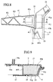
- Figs. 8 and 9 show another embodiment in connection with the modification of the first embodiment of the invention. Note, constituents corresponding to those of the first embodiment are indicated with the same reference numerals respectively and their overlapping descriptions are eliminated. In these figures, there are mainly shown the upper hood ridge member 41 and the front-pillar outer member 9.
- Fig. 8 shows a side view of the embodiment, similar to Fig. 3.
- Fig. 9 is a sectional view taken along a line H-H of Fig. 8.
- the rear vertical wall 41g of the part 41 is extended to form an extension vertical wall 41j which is joined to the rear vertical wall 31 of the front-pillar outer member 9 along the vehicle's width direction.
- the extended rear vertical wall 41g can butt against the whole inner face of the vertical wall 33, while the wall 41j can butt against the whole vertical wall 31.
- the up-and-down input (force) transmitted from the suspension can be transmitted to the front-pillar through a shear zone between the vertical wall 41g and the inner face of the vertical wall 33 and a plane contact between the vertical wall 41j and the rear vertical wall 31. Subsequently, the so-transmitted input can be further transmitted from the front pillar to the whole framework members of the vehicle body. Further, the twisting force of the upper hood ridge member 41 can be transmitted to the front pillar through the surface contact between the vertical wall 41g and the vertical wall 33 and the surface contact between the extension vertical wall 41j and the rear vertical wall 31. Subsequently, the so-transmitted twisting force can be further transmitted from the front pillar to the whole framework members more certainly.
- Fig. 10A is a sectional view taken along a line G1-G1 of Fig. 3
- Fig. 10B a sectional view taken along a line G2-G2 of Fig. 3
- Fig. 10C is a sectional view taken along a line G3-G3 of Fig. 3.
- main dies for molding the suspension attachment member 37 are withdrawn along directions E1 and E2, while a molding die for the upper hood ridge member 41 is withdrawn along a direction E3.
- rapping it is possible to form the hood ridge 11 in one body with ease.
- the respective parts are made of light metals, for example, aluminum alloy, magnesium alloy, etc. in common with the above-mentioned embodiments, the above metals may be replaced with other light metals or other materials, of course.
Landscapes
- Chemical & Material Sciences (AREA)
- Engineering & Computer Science (AREA)
- Life Sciences & Earth Sciences (AREA)
- Materials Engineering (AREA)
- Wood Science & Technology (AREA)
- Organic Chemistry (AREA)
- Combustion & Propulsion (AREA)
- Transportation (AREA)
- Mechanical Engineering (AREA)
- Body Structure For Vehicles (AREA)
Abstract
Description
- The present invention relates to a vehicle body structure. More particularly, it relates to the body structure in the circumference of an air box of the vehicle body.
- As the earlier art body structure in the circumference of the air box in a vehicle, Japanese Patent Publication (kokai) No. 6-329051 discloses one body structure where the air box is connected with both of a front pillar and a hood ridge on one side of the vehicle body.
- In detail, the air box is arranged so as to extend along the direction of a vehicle's width, forming an automotive framework member. The above front pillar is arranged on each end of the air box in the vehicle's width direction. Each front pillar is arranged to extend along the upward-and-downward direction of the vehicle body, also forming one automotive framework member. The hood ridge is arranged on each side of the vehicle body, in its front section. On each side of the vehicle body, the hood ridge is arranged to extend along the fore-and-aft direction of the vehicle body, also forming one automotive framework member.
- The air box is provided, on each side in the width direction, with a horizontal flange. On the other hand, the hood ridge has a joint surface defined for integration with the air box. In assembling, the above horizontal flange of the air box is piled on the joint surface defined on the hood ridge. Successively, the flange is connected to the joint surface by welding. Besides the joint surface, the hood ridge has a lateral flange formed to project from its sidewall sideways. While, the front pillar has a flange formed to project from its sidewall sideways, for abutment with the lateral flange of the hood ridge. In order to connect the front pillar with the hood ridge on each side of the vehicle body, the lateral flange of the hood ridge is butted against the flange of the front pillar and successively welded to the same flange into one body.
- However, the above-mentioned body structure has a problem to be solved. That is, if an external force via an automotive suspension in the upward-and-downward direction, so-called "suspension input" is applied on the hood ridge, the resultant bending of the hood ridge allows a force to act on the above connections between the air box and the hood ridge and between the hood ridge and the front pillar in a direction to separate the horizontal flange of the air box from the joint surface of the hood ridge and separate the lateral flange of the hood ridge from the flange of the front pillar. In order to avoid the occurrence of separations, it is necessary to enhance the bending rigidity of the hood ridge, for example, by increasing a plate thickness of each constituent of the structure. However, such an increase in plate thickness causes the body structure to be heavy-weighted as a matter of course.
- Meanwhile, in view of reducing the weight of a vehicle body and the number of its components, there is a vehicle body in recent development, which is made of a casting of light metal, for example, aluminum alloy, magnesium alloy, etc.
- In spite of the attempt for lightweight, the above-mentioned conventional body structure still causes the plate thickness to be increased in view of ensuring the bending rigidity of each hood ridge. In other words, there is still remained a limit for the light-weight body structure due to such an increase in plate thickness.
- Under the above circumstance, it is an object of the present invention to provide a body structure in the circumference of an air box, by which the vehicle body can be light-weight furthermore.
- According to the invention, the above-mentioned object is accomplished by a vehicle body structure, comprising:
- an air box arranged near front pillars of the vehicle to extend along a width direction of the vehicle;
- front-pillar inner members arranged on both sides of the air box in the width direction, each front-pillar inner member extending along an upward-and-downward direction of the vehicle;
- front-pillar outer members arranged on both sides of the air box in the direction of the vehicle's width, each front-pillar outer member extending along the upward-and-downward direction of the vehicle; and
- hood ridges arranged on both sides of the air box in the direction of the vehicle's width, each hood ridge having a upper hood ridge member formed to extend along a fore-and-aft direction of the vehicle.
-
- In the vehicle body structure, the front-pillar inner member has a pillar-inner vertical wall formed generally along the fore-and-aft direction of the vehicle, an air-box socket formed inside the pillar-inner vertical wall in the width direction to receive the air box from its underside, and an air-box joint flange formed on the upper part of the front-pillar inner member to join it to the air box. The upper hood ridge member has a fore-and-aft-directional vertical wall formed with an opening for joint so as to extend in the fore-and-aft direction and also along the pillar-inner vertical wall's surface being outside in the direction of the vehicle's width, and a width-directional vertical wall formed at a rear part of the upper hood ridge member to extend along the direction of the vehicle's width. The front-pillar outer member has a notch formed for engagement with the rear part of the upper hood ridge member. The air box is provided with a flange to be joined to the air-box socket of the front-pillar inner member and a joint surface to be piled on the air-box joint flange. In the structure, the air box, the front-pillar inner members, the front-pillar outer members and the hood ridges are joined together.
-
- Fig. 1 is a perspective view of the overall outward appearance of a vehicle body to which the present invention is to be applied;
- Fig. 2 is an exploded perspective view of a vehicle body structure in accordance with one embodiment of the invention;
- Fig. 3 is a partially-omitted side view of the assembled vehicle body structure of the embodiment, also viewed from the outside in the direction of a vehicle's width;
- Fig. 4 is a sectional view taken along a line A-A of Fig. 3;
- Fig. 5 is a sectional view taken along a line B-B of Fig. 3;
- Fig. 6 is a sectional view taken along a line C-C of Fig. 3;
- Fig. 7 is a sectional view taken along a line D-D of Fig. 3;
- Fig. 8 is a partially-omitted side view of the vehicle body structure in modification of the invention, also viewed from the outside in the direction of a vehicle's width;
- Fig. 9 is a sectional view taken along a line H-H of Fig. 8;
- Figs. 10A, 10B,and 10C are respective views showing various rapping directions for the hood-ridge member, in which Fig. 10A is a sectional view taken along a line G1-G1 of Fig. 3, Fig. 10B is a sectional view taken along a line G2-G2 of Fig. 3, and Fig. 10C is a sectional view taken along a line G3-G3 of Fig. 3.
-
- Figures 1 to 7 illustrate the first embodiment of the present invention.
- In these figures, Fig. 1 illustrates a vehicle body VB equipped with a body structure in accordance with an embodiment of the invention. Fig. 2 is an exploded perspective view of the body structure in the circumference of an air box in the vehicle body VB. As shown in the figure, the vehicle body structure mainly comprises an
air box 1, aninner member 7 to be joined to theair box 1 to form a front pillar, anouter member 9 also forming the front pillar together with theinner member 7, and ahood ridge 11 to be joined to theouter member 9 and theinner member 7. Note, theinner member 7 and theouter member 9 will be referred as "front-pillarinner member 7" and "front-pillarouter member 9", respectivelyReference numeral 13 designates a roof structure to be joined to the front-pillarouter member 9.Reference numeral 15 denotes a front side member to be connected with thehood ridge 11. As shown in Fig. 1, the above constituents of the vehicle body structure and thefront side member 15 are arranged on each side of the vehicle body VB in a direction of the body's width, beside theair box 1. Therefore, although the vehicle body VB is provided, on both sides thereof, with two body structure, the embodiment of the invention will be described with reference to one body structure on one side of the vehicle body VB. Note that both front ends of thefront side members 15 are respectively connected to across member 2 which extends in the direction of the body's width. This direction will be referred as "vehicle's width direction", below. - In the embodiment, the front-pillar
inner member 7, the front-pillarouter member 9, and thehood ridge 11 are made of castings of light metal, for example, aluminum alloy, magnesium alloy, etc. Theair box 1 may be made from plate materials of the same light metal. Theroof structure 13 is made of a casting of the same light metal. Thefront side member 15 is made of an extrusion of the same light metal. In this way, since the whole vehicle body is made of the light metal, the light-weightiness can be progressed from a point of view of materials remarkably. - The
air box 1, which is a framework member disposed in the vehicle's width direction, has a wall 1a formed to extend along the above direction. On one side of theair box 1 in the vehicle's width direction, ahorizontal flange 1b is formed to project from the end of thebox 1 laterally. Thehorizontal flange 1b is provided, on its under-side, with a joint surface with the front-pillarinner member 7. On the lowermost part of theair box 1, avertical flange 1c is formed so as to project further downward. - The front-pillar
inner member 7 has a "pillar-inner" vertical wall 17a formed to extend along a fore-and-aft direction of the vehicle. Inside the vertical wall 17a in the vehicle's width direction, an "air-box"socket 19 for receiving theair box 1 is formed to project inward of the vehicle's width direction. The air-box socket 19 is provided with asocket part 19a in the form of a groove for receiving theflange 1c. At the top of themember 7, it has aflange 21 for connecting themember 7 with theair box 1. Thisflange 21 is formed so as to project outward of the vehicle's width direction while directing itsjoint surface 21a upward. - The front-pillar
outer member 9 has anupper part 23 and alower part 25. Theupper part 23 is formed to succeed thelower part 25 through an inflectingpart 27, forming an inside structure of the vehicle body. Aside sill 28 is formed to succeed thelower part 25. Thelower part 25 generally comprises a frontvertical wall 29 extending along the vehicle's width direction, a rearvertical wall 31 also extending along the vehicle's width direction,and an outervertical wall 33 extending along the vehicle's fore-and-aft direction. The frontvertical wall 29 is provided, on an upper part thereof, with anotch 35. - The
hood ridge 11 includes a suspension attachment member (part) 37, a housing member (part) 39,and a upper hood ridge member (part) 41, all of which are formed into one casing body of light metal. Thus, in comparison with the arrangement where these elements are made of plate materials and welded into one body, thehood ridge 11 of the embodiment allows the number of components to be reduced, thereby facilitating the production. - The
suspension attachment member 37 is an element to be attached to a suspension (not shown) allowing a wheel to carry the vehicle body VB. Thesuspension attachment member 37 is provided, at a top face thereof, with asuspension attachment hole 37a for attachment with the suspension. In assembling, thehousing member 39 has an upper portion joined to thesuspension attachment member 37. Thehousing member 39 further includes aflange 39a formed on its lower portion, for connection with thefront side member 15 which forms one of lower frameworks of the vehicle body VB. - The upper
hood ridge member 41 is integrally joined to an upper portion of the housing member 5 outside in the vehicle's width direction and also formed so as to lengthen in the vehicle's fore-and-aft direction, forming the framework of the vehicle body. The upperhood ridge member 41 comprises anupper wall 41a, alower wall 41b, and a "fore-and-aft-directional"vertical wall 41c connecting theupper wall 41a with thelower wall 41b, providing a substantial U-shaped cross section. Thelower wall 41b is formed somewhat longer than theupper wall 41a in the vehicle's width direction, thereby providing ajoint flange 41d. Thevertical wall 41c is provided with ajoint opening 41e. The rear end of the upperhood ridge member 41 is blocked up with a "width-directional"vertical wall 41f extending along the vehicle's width direction. Thevertical wall 41f has ajoint flange 41g arranged outside of the vehicle's width direction. On the lowermost end of thevertical wall 41f, avertical wall 41h is formed so as to extend along the vehicle's width direction. Inside the so-constructed upperhood ridge member 41, a plurality of reinforcement ribs 41i are formed so as to extend along the vehicle's width direction. These ribs 41i are provided to connect theupper wall 41a, thelower wall 41b, and also thevertical wall 41c with each other. - The
front side member 15 connected with the underside of thehood ridge 11 forms the lower framework of the vehicle body VB and extends along the vehicle's fore-and-aft direction, which is similar to the upperhood ridge member 41. At an upper corner of thefront side member 15 outside of the vehicle's width direction, ajoint flange 15a is formed so as to project obliquely upward, but inward of the vehicle's width direction. Further, thefront side member 15 has a similarly-inclinedjoint surface 15b formed to succeed to thejoint flange 15a. - The
roof structure 13 has a front-pillarouter part 13a formed to fit with an external face of theupper part 23 of the front-pillarouter member 9. This front-pillarouter part 13a also forms a panel that extends from the roof, along an external surface of a front pillar of the vehicle. This front-pillarouter part 13a is combined with theupper part 23 of the front-pillarouter member 9 so as to define one closed-sectional structure. The lower end of theroof structure 13 is further elongated to define ajoint wall 13b. The joint wall has avertical wall 13c, anupper flange 13d,and alower flange 13e. - Fig. 3 is a partially-omitted side view of the assembly. In the assembly, the
air box 1, the front-pillarinner member 7, the front-pillarouter member 9, thehood ridge 11, theroof structure 13, and thefront side member 15 are joined together. Figs. 4 to 7 show respective sections of the above assembly. That is, Fig. 4 is a sectional view taken along a line A-A of Fig. 3. Fig. 5 is a sectional view taken along a line B-B and Fig. 6 a sectional view taken along a line C-C. Fig. 7 is a sectional view taken along a line D-D of Fig. 3. - As shown in Figs. 2 and 3, the rear part of the upper
hood ridge member 41 is fitted into thenotch 35 of the front-pillarouter member 9 and thevertical wall 41g is united with the outervertical wall 33. In detail, the circumference of thenotch 35 is welded to thevertical wall 41g, while thevertical wall 41g is welded to an inside face of the outervertical wall 33. Further, the lowervertical wall 41h is brought into surface contact with an inside face of the frontvertical wall 29 and joined thereto by welding. In this state, thevertical wall 41f of the upperhood ridge member 41 occupies a position substantially identical to a position of thevertical wall 29 in the fore-and-aft direction of the vehicle. - As shown in Figs. 3 to 5, the
vertical wall 41c of the upper hood-ridge part 41 is butted against the outer face of thevertical wall 17 of the front-pillarinner member 7. While, thejoint flange 21 of themember 7 is joined to the upper wall's portion (41a) fallen a degree. In this state, the circumference of theopening 41e is welded to thevertical wall 17 and thejoint flange 21 of themember 7 is welded to theupper wall 41a of the upperhood ridge member 41. - The
horizontal flange 1b of theair box 1 is piled on thejoint surface 21a of thejoint flange 21 and subsequently, the former is joined to the latter by welding. Theother flange 1c of theair box 1 is inserted into thegroove 19a of thesocket 19 of themember 7 and joined thereto by adhering. In Fig. 4, anarea 43 shown with doubly-slanted lines forms an adhering face defined along the up-and-down direction of the vehicle. - As shown in Figs. 3 to 5, the front-pillar
outer part 13a of theroof structure 13 is welded to theupper part 23 of the front-pillarouter member 9. Similarly, thevertical wall 13c of thestructure 13 is laid and welded to the outward opening of the upperhood ridge member 41, while thejoint flange 13d is laid and welded to theupper wall 41a of thepart 41. The lowermostjoint flange 13e is piled on thejoint flange 41d of the upperhood ridge member 41 from the upside and welded to theflange 41d. - As shown in Figs. 3, 6, and 7, the
lower part 25 of theouter pillar member 9 is welded to thevertical wall 17 of the front-pillarinner member 7. Similarly, the rear portion of thevertical wall 17 of theroof structure 13 is connected with thevertical wall 41g of the upperhood ridge member 41 by welding. - The
vertical wall 17 of the front-pillarinner member 7 is also welded to the rear side of thehousing member 39 of thehood ridge 11. Thejoint flange 15a and thejoint face 15b of thefront side member 15 are butted on thejoint flange 39a at the lowermost end of thehood ridge 11 in plane and welded into one body. - Under the above condition, as shown in Fig. 3, the
air box 1 is positioned on the front-and-upper side of apoint 49. At thepoint 49, aline 45 intersects with anotherline 47. Theline 45 extends along the upper part of the front-pillarouter part 9 and also passes through its center in the direction of its width. Theline 47 extends along thehood ridge 11 in the fore-and-aft direction and also passes through its center of the upward-and-downward direction. Further, as shown in Fig. 4, theair box 1 is arranged so that its center of the upward-and-downward direction shifts from the center of the upperhood ridge member 41 of the upward-and-downward direction, upward at a distance S. - In the so-assembled structure, the rear part of the
part 41 is welded to thevertical wall 17 of theinner member 7 and thevertical wall 33 of theouter member 9 with shear surfaces. As shown in Fig. 3, if the structure is loaded by a suspension input F1 to apply a moment M on the upperhood ridge member 41, then the force of the moment M is transmitted to the front pillar having high welding strength, through the shear surfaces. Thus, the above force is transmitted from the front pillar to the framework members, such as a roof rail, certainly. - Repeatedly, the upper
hood ridge member 41 is joined to thejoint flange 21 of theinner member 7 and thevertical wall 41h is also joined to thevertical wall 29, in respective surface contacts. Thus, the so-completed joint structure allows the suspension input of the upward-and-downward direction to be transmitted from thepart 41 to theouter member 9 and theinner member 7 through the surface contacts, thereby distributing the force to the overall framework members certainly. - As to the twisting of the vehicle body caused by the suspension input etc., the
socket 19 of theinner member 7 bears twisting forces f1, f2 through the part 41 (Fig. 4) in the fore-and-aft direction of the vehicle body. Consequently, thesocket part 19a comes into surface contact with thejoint flange 1c. Additionally, since thejoint flange 21 comes into surface contact with thehorizontal flange 1b of theair box 1 in the upward-and-downward direction, the above forces are transmitted to the opposite side of the vehicle's width direction, through theair box 1. Then, the forces are dispersed to the overall framework members through the opposite front pillar. - As the
vertical wall 13c of theroof structure 13 covers the opening of the upperhood ridge member 41 to define the closed section, the twisting rigidity of thepart 41 is enhanced to enable its wall thickness to be reduced. According to such the structure, it is possible to improve the load-transmitting function while reducing the weight of the body structure. - The
vertical wall 41f of the upperhood ridge member 41 and thevertical wall 29 of the front-pillarouter member 9 are substantially equal to each other in terms of position of the fore-and-aft direction of the vehicle. Therefore, the periphery of thewall 41f can butt against thevertical wall 29 of theouter member 9 or the inner periphery of thenotch 35 close to thewall 29. Consequently, the twisting force on thepart 41 can be transmitted from the circumference of thevertical wall 41f to the front pillar via thevertical wall 29 of theouter member 9 or the inner periphery of thenotch 35, thereby transmitting the twisting force to the overall framework members through the front pillar. - Since the air box's center of the upward-and-downward direction shifts from the same directional center of the upper
hood ridge member 41 upward at the distance S, the twisting input m (Fig. 4) of thepart 41 acts as a compressive force fa, so that it can be transmitted to the opposite side of the vehicle's width direction through the whole wall 1a of theair box 1. Owing to such the load transmission, it is possible to transmit the force to the overall framework members through the opposite front pillar more certainly. - As shown in Fig. 4, since the
socket part 19a of thesocket 19 of theinner member 7 adheres to thejoint flange 1c through the adheringface 43 along the upward-and-downward direction, such the joint allows the same-directional force to be received by a shear force having a high adhering strength, whereby the suspension input can be transmitted from theinner member 7 to theair box 1 through the adheringface 43 and,subsequently, from theair box 1 to the overall framework members through the front pillars on both sides of thebox 1, more certainly. - Repeatedly, note that the
air box 1 is positioned on the front-and-upper side of thepoint 49 where theline 45 extending along the upper part of the front-pillarouter part 9 and also passing through its center in the direction of its width intersects with theline 47 extending along thehood ridge 11 in the fore-and-aft direction and also passing through its center of the upward-and-downward direction. Additionally, on each side of the vehicle, the front-pillarinner member 7, thehood ridge 11, and the front-pillarouter member 9 are all made of castings of light metal, while theair box 1 is made of plate materials of light metal. Consequently, theair box 1 can be utilized as one bending member making the best use of feature of the plate materials with great stretches. Thus, the suspension input can be received by theair box 1 as a bending force to be applied thereon, so that the force is transmitted to the opposite side of the vehicle body in the vehicle's width direction. Not only for the opposite side, but also for the overall framework members, more certainly. - According to the embodiment, since the suspension input can be transmitted to the overall framework members effectively, it is possible to complete the load transmission without increasing the wall thickness of the structure. Further, owing to the formation of the body structure of light metals, the reduction in weight can be progressed. Again, owing to the adoption of castings etc. of light metal, the reduction in number of components can be progressed, too.
- Figs. 8 and 9 show another embodiment in connection with the modification of the first embodiment of the invention. Note, constituents corresponding to those of the first embodiment are indicated with the same reference numerals respectively and their overlapping descriptions are eliminated. In these figures, there are mainly shown the upper
hood ridge member 41 and the front-pillarouter member 9. Fig. 8 shows a side view of the embodiment, similar to Fig. 3. Fig. 9 is a sectional view taken along a line H-H of Fig. 8. - In this embodiment, the rear
vertical wall 41g of thepart 41 is extended to form an extensionvertical wall 41j which is joined to the rearvertical wall 31 of the front-pillarouter member 9 along the vehicle's width direction. With the structure, in spite of the twisting or bending of thepart 41, the extended rearvertical wall 41g can butt against the whole inner face of thevertical wall 33, while thewall 41j can butt against the wholevertical wall 31. - Accordingly, the up-and-down input (force) transmitted from the suspension can be transmitted to the front-pillar through a shear zone between the
vertical wall 41g and the inner face of thevertical wall 33 and a plane contact between thevertical wall 41j and the rearvertical wall 31. Subsequently, the so-transmitted input can be further transmitted from the front pillar to the whole framework members of the vehicle body. Further, the twisting force of the upperhood ridge member 41 can be transmitted to the front pillar through the surface contact between thevertical wall 41g and thevertical wall 33 and the surface contact between the extensionvertical wall 41j and the rearvertical wall 31. Subsequently, the so-transmitted twisting force can be further transmitted from the front pillar to the whole framework members more certainly. - Additionally, owing to the provision of a
horizontal wall 41k connecting thevertical wall 41f to thevertical walls hood ridge member 41. Therefore, it is possible to complete both shear and surface contact between the rearvertical wall 41g and thevertical wall 33 of the front-pillarouter member 9 and the surface contact between thevertical wall 41j and thevertical wall 31. Further, owing to the contribution on force transmission of thehorizontal wall 41k, it is possible to perform the force transmission on the whole framework members more certainly. - We now explain a rapping direction in case of forming the
hood ridge 11 by a casting of light metal. In the related figures, Fig. 10A is a sectional view taken along a line G1-G1 of Fig. 3, Fig. 10B a sectional view taken along a line G2-G2 of Fig. 3, and Fig. 10C is a sectional view taken along a line G3-G3 of Fig. 3. - In common with the shown examples, main dies for molding the
suspension attachment member 37 are withdrawn along directions E1 and E2, while a molding die for the upperhood ridge member 41 is withdrawn along a direction E3. By such rapping, it is possible to form thehood ridge 11 in one body with ease. - Although the respective parts are made of light metals, for example, aluminum alloy, magnesium alloy, etc. in common with the above-mentioned embodiments, the above metals may be replaced with other light metals or other materials, of course.
- Also in such a case, it is possible to restrict the increasing in both wall-thickness and weight of the body structure while maintaining the effective transmission of loads.
- The entire contents of Japanese Patent Application No. 11-264563 (filed on September 17, 1999) is incorporated by reference herein.
- The scope of the invention is defined with reference to the following claims.
Claims (10)
- A vehicle body structure comprising:an air box (1) near front pillars of the vehicle body, to extend along a width direction;front-pillar inner members (7) on both sides of the air box (1) in the width direction, each front-pillar inner member extending along an upward-and-downwardl direction;front-pillar outer members (9) on both sides of the air box (1) in the width direction, each front-pillar outer member extending along the upward-and-downward direction; andhood ridges (11) on both sides of the air box (1) in the width direction, each hood ridge having a upper hood ridge member (41) which extends along a fore-and-aft direction;
wherein:each front-pillar inner member (7) has a pillar-inner rising wall (17) extending generally along the fore-and-aft direction, an air-box socket (19) inside the pillar-inner rising wall (17) in the width direction, to receive the air box (1) from its underside, and an air-box joint flange (21) on the upper part of the front-pillar inner member (7), to join it to the air box (1);each upper hood ridge member (41) has a fore-and-aft directional rising wall (41c) with an opening (41e), outside the pillar-inner rising wall (17), and a width-directional rising wall (41f) in the rear part of the upper hood ridge member (41);each front-pillar outer member (9) has a notch (35) for engagement with the rear part of the respective upper hood ridge member (41);the air box (1) has respective flanges (1c) to be joined to the respective air-box sockets (19) of the respective front-pillar inner members (7) and respective joint surfaces to be superposed on the respective air-box joint flanges (21); andthe air box (1), the front-pillar inner members (7), the front-pillar outer members (9), and the hood ridges (11) are joined together. - A vehicle body structure as claimed in claim 1, wherein:the upper hood ridge member (41) has a rear rising wall (41g) at an outer edge of the width-directional rising wall (41f) along the fore-and-aft direction; andthe rear rising wall (41g) is joined to a fore-and-aft directional rising wall (33) on the front-pillar outer member (9) along the fore-and-aft direction.
- A vehicle body structure as claimed in claim 2, wherein:the width-directional or rear rising wall (41f or 41g) of the upper hood ridge member (41) is elongated or extended to provide an extension rising wall (41j) extending along the width direction; andthe extension rising wall (41j) is joined to a width-directional rising wall (31) on the front-pillar outer member (9) along the width direction.
- A vehicle body structure as claimed in claim 3, wherein the width-directional rising wall (41f), the rear rising wall (41g), and the extension rising wall (41j) are joined to each other through a hood-ridge lateral wall (41k) on the rear side of the upper hood ridge member (41).
- A vehicle body structure as claimed in any preceding claim, wherein a roof structure (13) is partially joined to the rear portion of the upper hood ridge member (41), thereby defining a closed sectional structure.
- A vehicle body structure as claimed in any preceding claim, wherein the width-directional rising wall (41f) of the upper hood ridge member (41) and a width-directional rising wall (41f) of the front-pillar outer member (9) are respectively arranged in positions substantially identical to each other in the fore-and-aft direction.
- A vehicle body structure as claimed in any preceding claim, wherein the air-box (1) is arranged so that its centre in the up-and-down direction is on the upside of the centre of the upper hood ridge member (41) in the up-and-down direction.
- A vehicle body structure as claimed in any preceding claim, wherein the air-box sockets and the air-box joint flanges are provided with adhering surfaces.
- A vehicle body structure as claimed in any preceding claim, wherein at least the front-pillar inner members (7), the hood ridges (11), and the front-pillar outer members (9) are light-metal castings.
- A vehicle body structure as claimed in any preceding claim, wherein:the air-box (1) is positioned on the front-and-upper side of a point where a line (45) extending along the upper part of the front-pillar outer member (9) and also passing through its center in the direction of its width intersects with another line (47) extending along the hood ridge (11) in the fore-and-aft direction and also passing through its center in the upward-and-downward direction; andthe front-pillar inner member (7), the hood ridge (11), and the front-pillar outer member (9) are light-metal castings, while the air box (1) is made of light-metal plate material.
Applications Claiming Priority (2)
| Application Number | Priority Date | Filing Date | Title |
|---|---|---|---|
| JP26456399A JP3436201B2 (en) | 1999-09-17 | 1999-09-17 | Structure around the body air box |
| JP26456399 | 1999-09-17 |
Publications (3)
| Publication Number | Publication Date |
|---|---|
| EP1084936A2 true EP1084936A2 (en) | 2001-03-21 |
| EP1084936A3 EP1084936A3 (en) | 2002-04-10 |
| EP1084936B1 EP1084936B1 (en) | 2004-07-14 |
Family
ID=17405032
Family Applications (1)
| Application Number | Title | Priority Date | Filing Date |
|---|---|---|---|
| EP00307893A Expired - Lifetime EP1084936B1 (en) | 1999-09-17 | 2000-09-13 | Vehicle body structure |
Country Status (4)
| Country | Link |
|---|---|
| US (1) | US6209950B1 (en) |
| EP (1) | EP1084936B1 (en) |
| JP (1) | JP3436201B2 (en) |
| DE (1) | DE60012103T2 (en) |
Cited By (5)
| Publication number | Priority date | Publication date | Assignee | Title |
|---|---|---|---|---|
| EP1256509A3 (en) * | 2001-05-11 | 2004-05-06 | Daihatsu Motor Company, Ltd. | Body structure of automobile |
| FR2929580A1 (en) * | 2008-04-07 | 2009-10-09 | Peugeot Citroen Automobiles Sa | FRONT FOOT REINFORCED OF A MOTOR VEHICLE. |
| CN105517881A (en) * | 2013-09-04 | 2016-04-20 | 本田技研工业株式会社 | Vehicle body front portion structure, and vehicle body assembly method |
| FR3075152A1 (en) * | 2017-12-20 | 2019-06-21 | Renault S.A.S | BODY STRUCTURE OF A MOTOR VEHICLE |
| US20220194479A1 (en) * | 2020-12-22 | 2022-06-23 | Hyundai Motor Company | Draining Structure for Cowl |
Families Citing this family (41)
| Publication number | Priority date | Publication date | Assignee | Title |
|---|---|---|---|---|
| JP3518437B2 (en) * | 1999-09-17 | 2004-04-12 | 日産自動車株式会社 | Structure of suspension mounting part of vehicle body |
| JP3446712B2 (en) * | 2000-03-10 | 2003-09-16 | 日産自動車株式会社 | Car front body structure |
| KR100392086B1 (en) * | 2000-11-24 | 2003-07-23 | 현대자동차주식회사 | Cowl side part T type box structure of vehicle |
| US6769733B2 (en) * | 2001-10-16 | 2004-08-03 | Alcoa Inc. | Bulkhead assembly for a motor vehicle |
| FR2855810B1 (en) * | 2003-06-03 | 2005-07-29 | Plastic Omnium Cie | WING SUPPORT FOR MOTOR VEHICLE |
| US7140674B2 (en) * | 2003-08-29 | 2006-11-28 | Mitsubishi Jidosha Kogyo Kabushiki Kaisha | Vehicle body frame structure |
| US7066533B2 (en) * | 2004-06-03 | 2006-06-27 | Ford Global Technologies, Llc | Tubular front end structure for automobiles and method for making the same |
| JP4405327B2 (en) * | 2004-06-30 | 2010-01-27 | 本田技研工業株式会社 | Front fender structure |
| KR100644942B1 (en) * | 2004-10-05 | 2006-11-10 | 현대자동차주식회사 | Lower collision distribution structure of the vehicle floor |
| JP4404036B2 (en) * | 2005-09-21 | 2010-01-27 | トヨタ自動車株式会社 | Vehicle rear structure |
| JP4329791B2 (en) * | 2006-08-09 | 2009-09-09 | 日産自動車株式会社 | Vehicle front structure |
| JP4078657B1 (en) * | 2006-11-24 | 2008-04-23 | いすゞ自動車株式会社 | Body side structure of vehicle |
| DE102006055730A1 (en) * | 2006-11-25 | 2008-05-29 | Dr.Ing.H.C. F. Porsche Ag | MacPherson strut |
| JP5332129B2 (en) * | 2007-03-30 | 2013-11-06 | 三菱自動車工業株式会社 | Frame structure at the front of the vehicle |
| JP5119827B2 (en) * | 2007-09-25 | 2013-01-16 | 日産自動車株式会社 | Body structure |
| US7731272B2 (en) * | 2007-12-26 | 2010-06-08 | Toyota Motor Engineering & Manufacturing North America, Inc. | A-pillar force transfer structure |
| JP5581699B2 (en) * | 2010-01-12 | 2014-09-03 | トヨタ自動車株式会社 | Vehicle skeleton structure |
| DE102010034932A1 (en) * | 2010-08-20 | 2012-02-23 | Gm Global Technology Operations Llc (N.D.Ges.D. Staates Delaware) | Motor vehicle body with structurally reinforced front frame connection |
| DE102011119561A1 (en) * | 2011-11-26 | 2013-05-29 | GM Global Technology Operations LLC (n. d. Gesetzen des Staates Delaware) | Support structure component for the body of a motor vehicle |
| DE102011056737B4 (en) | 2011-12-21 | 2023-03-16 | Dr. Ing. H.C. F. Porsche Aktiengesellschaft | Front end structure of a motor vehicle |
| DE102013101697A1 (en) * | 2013-02-20 | 2014-08-21 | Dr. Ing. H.C. F. Porsche Aktiengesellschaft | Motor vehicle support structure |
| US20150001884A1 (en) * | 2013-06-28 | 2015-01-01 | GM Global Technology Operations LLC | One piece front hinge pillar and methods of making and using the same |
| US20150001889A1 (en) * | 2013-06-28 | 2015-01-01 | GM Global Technology Operations LLC | Adaptor for a front body hinge pillar |
| JP6299486B2 (en) | 2013-07-08 | 2018-03-28 | スズキ株式会社 | Body front structure |
| US20150210330A1 (en) * | 2014-01-30 | 2015-07-30 | GM Global Technology Operations LLC | Motor compartment structure for a vehicle and method of attaching a motor compartment to a vehicle |
| US9248868B2 (en) | 2014-05-29 | 2016-02-02 | Ford Global Technologies, Llc | Vehicle front end structure |
| US9114835B1 (en) | 2014-05-29 | 2015-08-25 | Ford Global Technologies, Llc | Vehicle front end structure |
| US9079617B1 (en) * | 2014-05-29 | 2015-07-14 | Ford Global Technologies, Llc | Vehicle front end joint |
| US9333989B2 (en) * | 2014-06-25 | 2016-05-10 | Ford Global Technologies, Llc | Vehicle frame bracket |
| US9371093B1 (en) | 2014-12-03 | 2016-06-21 | Toyota Motor Engineering & Manufacturing North America, Inc. | Vehicles having upper side member reinforcement portions |
| KR20170065382A (en) * | 2015-12-03 | 2017-06-13 | 기아자동차주식회사 | Cowl side reinforcing structure in vehicle |
| JP6504063B2 (en) * | 2016-01-20 | 2019-04-24 | マツダ株式会社 | Front body structure of the vehicle |
| KR101765637B1 (en) * | 2016-03-08 | 2017-08-07 | 현대자동차 주식회사 | Vehicle body structure using CFRP |
| US10093359B2 (en) * | 2016-06-29 | 2018-10-09 | Honda Motor Co., Ltd. | Vehicle front frame assembly, and methods of use and manufacture thereof |
| CN106218724B (en) * | 2016-07-29 | 2018-12-28 | 奇瑞新能源汽车技术有限公司 | On vehicle body A column with the connection structure under A column |
| WO2018025509A1 (en) * | 2016-08-01 | 2018-02-08 | 本田技研工業株式会社 | Vehicle body front structure |
| JP6520906B2 (en) * | 2016-12-19 | 2019-05-29 | トヨタ自動車株式会社 | Front pillar structure |
| DE102017200368A1 (en) * | 2017-01-11 | 2018-07-12 | Bayerische Motoren Werke Aktiengesellschaft | Bow of a motor vehicle |
| KR102660340B1 (en) * | 2019-03-25 | 2024-04-24 | 현대자동차주식회사 | Front body structure of vehicle |
| US12337900B2 (en) | 2023-05-12 | 2025-06-24 | Via Fortuna, Llc | Modular motor vehicle platforms and assembly methods |
| US12589702B2 (en) * | 2024-02-01 | 2026-03-31 | Honda Motor Co., Ltd. | Vehicle including a-pillar garnish extending into airflow gap and underneath hood |
Citations (1)
| Publication number | Priority date | Publication date | Assignee | Title |
|---|---|---|---|---|
| JPH06329051A (en) | 1993-05-25 | 1994-11-29 | Mazda Motor Corp | Automobile body structure |
Family Cites Families (7)
| Publication number | Priority date | Publication date | Assignee | Title |
|---|---|---|---|---|
| US4699419A (en) * | 1985-07-03 | 1987-10-13 | Toyota Jidosha Kabushiki Kaisha | Structure for connecting front pillar and cowl in vehicle |
| JP2514965B2 (en) * | 1987-04-30 | 1996-07-10 | 日産自動車株式会社 | Car body front structure |
| US5052742A (en) * | 1989-06-30 | 1991-10-01 | Toyota Jidosha Kabushiki Kaisha | Cowlside joint structure for use with vehicle |
| DE59102529D1 (en) * | 1990-12-20 | 1994-09-15 | Audi Ag | CARRIER CONNECTION ON A VEHICLE BODY. |
| DE19639052C2 (en) * | 1996-09-24 | 1998-07-09 | Daimler Benz Ag | Thin-walled die-cast part made of light metal as a structural component for car bodies |
| DE19801664C1 (en) * | 1998-01-17 | 1999-07-15 | Daimler Chrysler Ag | Method for assembling a cockpit module in a body shell |
| DE19819446A1 (en) * | 1998-04-30 | 1999-11-04 | Volkswagen Ag | Body structure of a motor vehicle |
-
1999
- 1999-09-17 JP JP26456399A patent/JP3436201B2/en not_active Expired - Fee Related
-
2000
- 2000-09-12 US US09/660,397 patent/US6209950B1/en not_active Expired - Fee Related
- 2000-09-13 DE DE60012103T patent/DE60012103T2/en not_active Expired - Fee Related
- 2000-09-13 EP EP00307893A patent/EP1084936B1/en not_active Expired - Lifetime
Patent Citations (1)
| Publication number | Priority date | Publication date | Assignee | Title |
|---|---|---|---|---|
| JPH06329051A (en) | 1993-05-25 | 1994-11-29 | Mazda Motor Corp | Automobile body structure |
Cited By (10)
| Publication number | Priority date | Publication date | Assignee | Title |
|---|---|---|---|---|
| EP1256509A3 (en) * | 2001-05-11 | 2004-05-06 | Daihatsu Motor Company, Ltd. | Body structure of automobile |
| FR2929580A1 (en) * | 2008-04-07 | 2009-10-09 | Peugeot Citroen Automobiles Sa | FRONT FOOT REINFORCED OF A MOTOR VEHICLE. |
| WO2009125098A3 (en) * | 2008-04-07 | 2009-12-17 | Peugeot Citroën Automobiles SA | Strengthened “a” pillar for a motor vehicle |
| CN101983154B (en) * | 2008-04-07 | 2014-03-12 | 标致·雪铁龙汽车公司 | Strengthened A pillar for motor vehicle |
| CN105517881A (en) * | 2013-09-04 | 2016-04-20 | 本田技研工业株式会社 | Vehicle body front portion structure, and vehicle body assembly method |
| EP3042830A4 (en) * | 2013-09-04 | 2017-08-02 | Honda Motor Co., Ltd. | Vehicle body front portion structure, and vehicle body assembly method |
| FR3075152A1 (en) * | 2017-12-20 | 2019-06-21 | Renault S.A.S | BODY STRUCTURE OF A MOTOR VEHICLE |
| WO2019120754A1 (en) * | 2017-12-20 | 2019-06-27 | Renault S.A.S | Motor vehicle body structure |
| US20220194479A1 (en) * | 2020-12-22 | 2022-06-23 | Hyundai Motor Company | Draining Structure for Cowl |
| US11634181B2 (en) * | 2020-12-22 | 2023-04-25 | Hyundai Motor Company | Draining structure for cowl |
Also Published As
| Publication number | Publication date |
|---|---|
| DE60012103D1 (en) | 2004-08-19 |
| US6209950B1 (en) | 2001-04-03 |
| JP2001088743A (en) | 2001-04-03 |
| EP1084936B1 (en) | 2004-07-14 |
| EP1084936A3 (en) | 2002-04-10 |
| JP3436201B2 (en) | 2003-08-11 |
| DE60012103T2 (en) | 2005-09-08 |
Similar Documents
| Publication | Publication Date | Title |
|---|---|---|
| EP1084936B1 (en) | Vehicle body structure | |
| EP1084937B1 (en) | Vehicle body structure | |
| US5002333A (en) | Under frame of a motor vehicle | |
| EP1873019B1 (en) | Vehicle bumper structure | |
| CN101720292B (en) | Construction method of load-bearing structure of motor vehicle body and load-bearing structure constructed therefor | |
| US8733822B2 (en) | Vehicle front structure | |
| JP5045322B2 (en) | Body structure of the back door opening | |
| EP1270377B1 (en) | Body upper structure for vehicle | |
| JPH06286652A (en) | Car body structure for automobile | |
| EP0908372A2 (en) | Construction of root portion of front side member | |
| KR102791606B1 (en) | Rigid reinforcement structure for rear underbody of the vehicle | |
| EP3632778B1 (en) | Front vehicle-body structure and vehicle | |
| JP2003237636A (en) | Body front structure | |
| JP2000095151A (en) | Rocker structure of vehicle | |
| CN108791507A (en) | Structure for vehicle body rear portion | |
| JP2000043754A (en) | Car body rear structure | |
| JPH09202262A (en) | Body connection structure | |
| JP3985769B2 (en) | Center pillar superstructure of vehicle | |
| US11214316B2 (en) | Vehicle body lower part structure | |
| JP5708536B2 (en) | Vehicle roof structure | |
| JP2001247057A (en) | Vehicular body lower part structure | |
| JP4905008B2 (en) | Body engine compartment structure | |
| JP5189622B2 (en) | Car body rear structure | |
| JPH10100934A (en) | Panel structure of two-door car | |
| JP3377888B2 (en) | Undercar body structure of car |
Legal Events
| Date | Code | Title | Description |
|---|---|---|---|
| PUAI | Public reference made under article 153(3) epc to a published international application that has entered the european phase |
Free format text: ORIGINAL CODE: 0009012 |
|
| 17P | Request for examination filed |
Effective date: 20001013 |
|
| AK | Designated contracting states |
Kind code of ref document: A2 Designated state(s): AT BE CH CY DE DK ES FI FR GB GR IE IT LI LU MC NL PT SE Kind code of ref document: A2 Designated state(s): DE FR GB |
|
| AX | Request for extension of the european patent |
Free format text: AL;LT;LV;MK;RO;SI |
|
| PUAL | Search report despatched |
Free format text: ORIGINAL CODE: 0009013 |
|
| AK | Designated contracting states |
Kind code of ref document: A3 Designated state(s): AT BE CH CY DE DK ES FI FR GB GR IE IT LI LU MC NL PT SE |
|
| AX | Request for extension of the european patent |
Free format text: AL;LT;LV;MK;RO;SI |
|
| AKX | Designation fees paid |
Free format text: DE FR GB |
|
| GRAP | Despatch of communication of intention to grant a patent |
Free format text: ORIGINAL CODE: EPIDOSNIGR1 |
|
| GRAS | Grant fee paid |
Free format text: ORIGINAL CODE: EPIDOSNIGR3 |
|
| GRAA | (expected) grant |
Free format text: ORIGINAL CODE: 0009210 |
|
| AK | Designated contracting states |
Kind code of ref document: B1 Designated state(s): DE FR GB |
|
| REG | Reference to a national code |
Ref country code: GB Ref legal event code: FG4D |
|
| REF | Corresponds to: |
Ref document number: 60012103 Country of ref document: DE Date of ref document: 20040819 Kind code of ref document: P |
|
| REG | Reference to a national code |
Ref country code: IE Ref legal event code: FG4D |
|
| ET | Fr: translation filed | ||
| PLBE | No opposition filed within time limit |
Free format text: ORIGINAL CODE: 0009261 |
|
| STAA | Information on the status of an ep patent application or granted ep patent |
Free format text: STATUS: NO OPPOSITION FILED WITHIN TIME LIMIT |
|
| REG | Reference to a national code |
Ref country code: IE Ref legal event code: MM4A |
|
| 26N | No opposition filed |
Effective date: 20050415 |
|
| PGFP | Annual fee paid to national office [announced via postgrant information from national office to epo] |
Ref country code: GB Payment date: 20070912 Year of fee payment: 8 |
|
| PGFP | Annual fee paid to national office [announced via postgrant information from national office to epo] |
Ref country code: DE Payment date: 20071004 Year of fee payment: 8 |
|
| PGFP | Annual fee paid to national office [announced via postgrant information from national office to epo] |
Ref country code: FR Payment date: 20070914 Year of fee payment: 8 |
|
| GBPC | Gb: european patent ceased through non-payment of renewal fee |
Effective date: 20080913 |
|
| REG | Reference to a national code |
Ref country code: FR Ref legal event code: ST Effective date: 20090529 |
|
| PG25 | Lapsed in a contracting state [announced via postgrant information from national office to epo] |
Ref country code: DE Free format text: LAPSE BECAUSE OF NON-PAYMENT OF DUE FEES Effective date: 20090401 |
|
| PG25 | Lapsed in a contracting state [announced via postgrant information from national office to epo] |
Ref country code: FR Free format text: LAPSE BECAUSE OF NON-PAYMENT OF DUE FEES Effective date: 20080930 |
|
| PG25 | Lapsed in a contracting state [announced via postgrant information from national office to epo] |
Ref country code: GB Free format text: LAPSE BECAUSE OF NON-PAYMENT OF DUE FEES Effective date: 20080913 |