EP1084922A2 - Système de freinage pour un train de wagons ferroviaires - Google Patents
Système de freinage pour un train de wagons ferroviaires Download PDFInfo
- Publication number
- EP1084922A2 EP1084922A2 EP00117259A EP00117259A EP1084922A2 EP 1084922 A2 EP1084922 A2 EP 1084922A2 EP 00117259 A EP00117259 A EP 00117259A EP 00117259 A EP00117259 A EP 00117259A EP 1084922 A2 EP1084922 A2 EP 1084922A2
- Authority
- EP
- European Patent Office
- Prior art keywords
- train consist
- freight
- computer
- disposed
- stopping distance
- Prior art date
- Legal status (The legal status is an assumption and is not a legal conclusion. Google has not performed a legal analysis and makes no representation as to the accuracy of the status listed.)
- Withdrawn
Links
- 238000000034 method Methods 0.000 claims abstract description 38
- 230000003137 locomotive effect Effects 0.000 claims abstract description 29
- 238000004891 communication Methods 0.000 claims abstract description 9
- 239000012530 fluid Substances 0.000 claims abstract description 9
- 230000001627 detrimental effect Effects 0.000 claims abstract description 7
- 230000002708 enhancing effect Effects 0.000 description 9
- 238000013461 design Methods 0.000 description 7
- 230000009471 action Effects 0.000 description 4
- 238000004458 analytical method Methods 0.000 description 4
- 230000008901 benefit Effects 0.000 description 4
- 230000006872 improvement Effects 0.000 description 4
- 230000008878 coupling Effects 0.000 description 3
- 238000010168 coupling process Methods 0.000 description 3
- 238000005859 coupling reaction Methods 0.000 description 3
- 230000000694 effects Effects 0.000 description 3
- 238000012986 modification Methods 0.000 description 3
- 230000004048 modification Effects 0.000 description 3
- 239000000872 buffer Substances 0.000 description 2
- 230000001276 controlling effect Effects 0.000 description 2
- 239000000463 material Substances 0.000 description 2
- 230000000979 retarding effect Effects 0.000 description 2
- 238000012360 testing method Methods 0.000 description 2
- 230000008859 change Effects 0.000 description 1
- 230000000052 comparative effect Effects 0.000 description 1
- 239000002131 composite material Substances 0.000 description 1
- 238000012937 correction Methods 0.000 description 1
- 230000001419 dependent effect Effects 0.000 description 1
- 238000011161 development Methods 0.000 description 1
- 238000005516 engineering process Methods 0.000 description 1
- 230000007613 environmental effect Effects 0.000 description 1
- 238000012423 maintenance Methods 0.000 description 1
- 239000000203 mixture Substances 0.000 description 1
- 230000007935 neutral effect Effects 0.000 description 1
- 230000000737 periodic effect Effects 0.000 description 1
- 230000009467 reduction Effects 0.000 description 1
- 230000001105 regulatory effect Effects 0.000 description 1
- 230000008439 repair process Effects 0.000 description 1
- 238000011160 research Methods 0.000 description 1
- 238000004088 simulation Methods 0.000 description 1
- 239000000725 suspension Substances 0.000 description 1
Images


Classifications
-
- B—PERFORMING OPERATIONS; TRANSPORTING
- B60—VEHICLES IN GENERAL
- B60T—VEHICLE BRAKE CONTROL SYSTEMS OR PARTS THEREOF; BRAKE CONTROL SYSTEMS OR PARTS THEREOF, IN GENERAL; ARRANGEMENT OF BRAKING ELEMENTS ON VEHICLES IN GENERAL; PORTABLE DEVICES FOR PREVENTING UNWANTED MOVEMENT OF VEHICLES; VEHICLE MODIFICATIONS TO FACILITATE COOLING OF BRAKES
- B60T8/00—Arrangements for adjusting wheel-braking force to meet varying vehicular or ground-surface conditions, e.g. limiting or varying distribution of braking force
- B60T8/18—Arrangements for adjusting wheel-braking force to meet varying vehicular or ground-surface conditions, e.g. limiting or varying distribution of braking force responsive to vehicle weight or load, e.g. load distribution
- B60T8/1893—Arrangements for adjusting wheel-braking force to meet varying vehicular or ground-surface conditions, e.g. limiting or varying distribution of braking force responsive to vehicle weight or load, e.g. load distribution especially adapted for railway vehicles
-
- B—PERFORMING OPERATIONS; TRANSPORTING
- B60—VEHICLES IN GENERAL
- B60T—VEHICLE BRAKE CONTROL SYSTEMS OR PARTS THEREOF; BRAKE CONTROL SYSTEMS OR PARTS THEREOF, IN GENERAL; ARRANGEMENT OF BRAKING ELEMENTS ON VEHICLES IN GENERAL; PORTABLE DEVICES FOR PREVENTING UNWANTED MOVEMENT OF VEHICLES; VEHICLE MODIFICATIONS TO FACILITATE COOLING OF BRAKES
- B60T13/00—Transmitting braking action from initiating means to ultimate brake actuator with power assistance or drive; Brake systems incorporating such transmitting means, e.g. air-pressure brake systems
- B60T13/10—Transmitting braking action from initiating means to ultimate brake actuator with power assistance or drive; Brake systems incorporating such transmitting means, e.g. air-pressure brake systems with fluid assistance, drive, or release
- B60T13/66—Electrical control in fluid-pressure brake systems
- B60T13/665—Electrical control in fluid-pressure brake systems the systems being specially adapted for transferring two or more command signals, e.g. railway systems
-
- B—PERFORMING OPERATIONS; TRANSPORTING
- B60—VEHICLES IN GENERAL
- B60T—VEHICLE BRAKE CONTROL SYSTEMS OR PARTS THEREOF; BRAKE CONTROL SYSTEMS OR PARTS THEREOF, IN GENERAL; ARRANGEMENT OF BRAKING ELEMENTS ON VEHICLES IN GENERAL; PORTABLE DEVICES FOR PREVENTING UNWANTED MOVEMENT OF VEHICLES; VEHICLE MODIFICATIONS TO FACILITATE COOLING OF BRAKES
- B60T8/00—Arrangements for adjusting wheel-braking force to meet varying vehicular or ground-surface conditions, e.g. limiting or varying distribution of braking force
- B60T8/26—Arrangements for adjusting wheel-braking force to meet varying vehicular or ground-surface conditions, e.g. limiting or varying distribution of braking force characterised by producing differential braking between front and rear wheels
- B60T8/266—Arrangements for adjusting wheel-braking force to meet varying vehicular or ground-surface conditions, e.g. limiting or varying distribution of braking force characterised by producing differential braking between front and rear wheels using valves or actuators with external control means
Definitions
- the present invention relates, in general, to the normal stopping distance that is required during a brake application on a braking arrangement utilized on a railway type freight car and, more particularly, this invention relates to both a method of and an apparatus for substantially minimizing the normal stopping distance required for a freight train consist during such brake application and, still more specifically, this invention relates to such a method of and an apparatus for substantially minimizing the normal stopping distance required during a brake application for a freight train consist that is equipped with a present day state of the art electrically controlled pneumatic (ECP) type braking arrangement.
- ECP electrically controlled pneumatic
- a brake control signal can be transmitted throughout the length of the train consist.
- brake control signal can be transmitted either electrically, over a trainline, or as a radio frequency (RF) type control signal.
- RF radio frequency
- brake control signals are transmitted to at least one electro-pneumatic type valve that is disposed on each freight car in a train consist in order to rapidly exhaust air from the brake pipe and, therefore, begin either a full service or an emergency brake application more quickly throughout the length of the train consist through the application of the requisite air pressure to the brake cylinders disposed on each car throughout the train consist.
- the present invention provides a method of significantly enhancing the brake performance of a brake system disposed on a freight train.
- Such method includes the steps of preprogramming preselected information into a computer disposed on a freight locomotive.
- the method further includes determining a speed of such freight train consist and communicating a signal that is indicative of such speed determined to such computer.
- the method includes the step of determining in such computer a pressure that can be applied to brake cylinders which will maintain substantially maximum adhesion between wheels being braked and rail surfaces in contact with such wheels and communicating a signal representative of such pressure determined to a pressure control valve in fluid communication with such brake cylinders. Thereafter maintaining a maximum pressure on such brake cylinders that will stop such train consist in a shortest possible distance while simultaneously substantially preventing wheel slide.
- this invention provides an apparatus for minimizing the stopping distance of a freight train.
- Such apparatus for minimizing the stopping distance of a freight train comprises a program having preselected information inputted into a computer disposed on a freight locomotive.
- the apparatus further includes a speed sensing means disposed on at least one of such locomotive and a freight car for determining a speed of such freight train consist and a means connected to such speed sensing means for communicating a signal that is indicative of the speed to such computer, so that such program can determine a pressure that can be applied to brake cylinders which will maintain substantially maximum adhesion between wheels being braked and rail surfaces in contact with such wheels.
- the final essential element of the apparatus is a means connected to such computer for communicating a signal representative of such pressure determined by the program to a pressure control valve disposed in fluid communication with such brake cylinders and maintaining a maximum pressure on such brake cylinders that will stop such train consist in a shortest possible distance while simultaneously substantially preventing wheel slide.
- Another object of the present invention is to provide an apparatus for enhancing the braking efficiency of a train consist which can be implemented at a relatively low cost by utilizing the equipment already present on electronically controlled railway braking systems.
- Still another object of the present invention is to provide a method of and an apparatus for enhancing the braking efficiency of a train consist which will significantly reduce the wheel slip while simultaneously maximizing the desired adhesion between the wheel and rail.
- Yet another object of the present invention is to provide a method of and an apparatus for enhancing the braking efficiency of a train consist which will be cost effective to implement.
- a further object of the present invention is to provide a method of and an apparatus for enhancing the braking efficiency of a train consist which will incorporate feedback control to provide optimum control of the braking system.
- Still yet another object of the present invention is to provide a method of and an apparatus for enhancing the braking efficiency of a train consist which can utilize pre-programmed adhesion curves to compensate for brake shoe coefficient fade during a brake application.
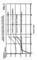
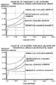
- Figure 1 Illustrated therein is a graph showing adhesion/adhesion demand with respect to time in seconds for various types of rail that can be encountered and for a full service / 286K GRL / 13.0% NBR theoretical single car stop on a level grade.
- the shortest stopping distance without incurring any significant detrimental wheel slide will normally occur by taking full advantage of the area under the adhesion curves for a particular retardation force/car weight adhesion demand.
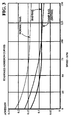
- Figure 2 is similar to Figure 1 and illustrates the adhesion/adhesion demand with respect to time in seconds for various types of rail that can be encountered and for a full service / 52,260 Lt. Wt. / 38.0% NBR theoretical single car stop on a level grade.
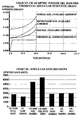
- Illustrated in Figure 3 is a graph of standard adhesion curves for different rail conditions programmed into a computer disposed on a locomotive. These standard adhesion curves are useful in carrying out the presently preferred embodiments of the invention.
- a method that will substantially achieve a minimum stopping distance of a freight train consist without incurring any significant detrimental wheel slide.
- Such method comprising the steps of preprogramming preselected information into a computer disposed on a freight locomotive and determining a speed of such freight train consist. A signal that is indicative of said speed determined is communicated to such computer disposed on such freight locomotive. Thereafter, determining in such computer a pressure that can be applied to brake cylinders which will maintain substantially maximum adhesion between wheels being braked and rail surfaces in contact with such wheels. Then, communicating a signal representative of such pressure determined to a pressure control valve in fluid communication with such brake cylinders and maintaining a maximum pressure on such brake cylinders that will stop such train consist in a shortest possible distance while simultaneously substantially preventing wheel slide.
- the method includes an additional step of providing preselected feedback information to such computer.
- the preselected information programmed into such computer disposed on a freight locomotive include a length of such train consist and such method includes an additional step of using the length in maintaining a maximum pressure on such brake cylinders that will stop such train consist in a shortest possible distance while simultaneously substantially preventing wheel slide.
- the preselected information programmed into such computer disposed on a freight locomotive may include a velocity dependence of wheel to rail adhesion and such method includes an additional step of using the velocity dependence of wheel to rail adhesion in maintaining a maximum pressure on such brake cylinders that will stop such train consist in a shortest possible distance while simultaneously substantially preventing wheel slide.
- Such preselected information programmed into such computer disposed on a freight locomotive may further include a weight of at least such train consist and the method includes an additional step of using the weight in maintaining a maximum pressure on such brake cylinders that will stop such train consist in a shortest possible distance while simultaneously substantially preventing wheel slide.
- the preselected information programmed into such computer disposed on a freight locomotive may include a weight of each car disposed in such train consist and the method includes an additional step of using the weight of such each car in maintaining a maximum pressure on such brake cylinders that will stop such train consist in a shortest possible distance while simultaneously substantially preventing wheel slide.
- the signal that is indicative of said speed is one of an electrical signal and a radio signal communicated to such computer disposed on such freight locomotive and the signal representative of such pressure is one of an electrical signal and a radio signal communicated to such pressure control valve disposed in fluid communication with such brake cylinders.
- the present invention further provides an apparatus for substantially achieving a minimum stopping distance of a freight train consist without incurring any significant detrimental wheel slide.
- the apparatus comprises a program having preselected information disposed in a computer located on a freight locomotive and a speed sensing means disposed on at least one of such locomotive and a freight car for determining a speed of such freight train consist.
- Such speed sensing means for communicating a signal that is indicative of the speed to such computer disposed on such freight locomotive, so that such program can determine a pressure that can be applied to brake cylinders which will maintain substantially maximum adhesion between wheels being braked and rail surfaces in contact with such wheels and a means connected to such computer for communicating a signal representative of such pressure determined by said program to a pressure control valve disposed in fluid communication with such brake cylinders and maintaining a maximum pressure on such brake cylinders that will stop such train consist in a shortest possible distance while simultaneously substantially preventing wheel slide.
- such means connected to the speed sensing means for communicating the signal that is indicative of such speed to such computer is a wire and the means connected to such computer for communicating a signal representative of such pressure determined by the program to such pressure control valve is also a wire.
- the means connected to such speed sensing means for communicating the signal that is indicative of such speed to such computer is a radio transmitter and such means connected to such computer for communicating a signal representative of such pressure determined by such program to such pressure control valve is also a radio transmitter.
- the apparatus further includes a means disposed on such train consist for determining a weight of such train consist and a means, such as a keyboard, disposed on such train consist for inputting information into such computer disposed on such locomotive.
- the performance of the British style brake systems have a tendency to be more conservative, when addressing adhesion concerns in the light car condition than the US and they tend to utilize the brakes in a much more demanding way in the loaded car condition.
- the data to be presented hereinafter has been calibrated to actual performance in the field for the British equipment and then extrapolated to show comparative data for typical US equipment. The calibration is simply an adjustment in average brake block coefficient for a particular set of braking conditions.
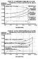
- Chart #1 shows that at an allowable 38% net brake ratio, the US system has entered the potential wheel slide area of the adhesion curves for bad rail.
- Chart #2 shows that the same car, under an emergency brake application, can achieve a 45.6% net brake ratio that increases the potential for wheel slide even more.
- Chart #3 and chart #4 show how much more braking we could do in order to stop the car in a shorter distance, without risking wheel slide, in the loaded condition with both full service and emergency brake applications.
- the draft gear typically forces the cars to a neutral position and controls slack energy in both "bunched” and “stretched” conditions.
- the only exceptions to this are the more wide spread use of articulated connectors and slackless drawbars. These units eliminate slack in their connections and thus severely reduce dynamic slack action and the need to control it.
- Grade braking and wheel tread temperatures need to also be considered when dissipating the energy of a moving freight car. Not only do we operate longer trains here in the US, but they are also an average 27% heavier gross rail load than the British freight cars (286K vs 225K GRL). In the US, dynamic braking is the preferred method of train control. The British system tends to use the power brakes more often and can do more of this type of braking due to their lighter freight cars and less kinetic energy. Braking heavier cars on grades can generate detrimental wheel tread temperatures if the shoe force and friction are too high for extended periods of time during the stopping or speed reduction event. The simulations above for the British 198.5K GRL stop raised the wheel temperature approximately 140° F during the estimated 50 second stop test.
- the British brake equipment used in these examples, consists of a modified WABCO TMX® truck mounted brake.
- the modifications consist of a larger 12 inch diameter brake cylinder, custom levers, 12° end extensions on the brake beams and brake shoes of a special composite material.
- This equipment and brake shoe material helped to achieve the presented stop distances.
- the brake shoe forces were in the neighborhood of 9,000 pounds per shoe, at full application. Having a brake shoe material with sufficient friction, that has minimal fade at high energy levels and being able to mechanically apply high brake shoe forces are key in attaining the demonstrated performance.
- Electronic braking can be used to improve the performance of brake systems, especially in the area of velocity dependent retarding forces.
- Charts 1 through 7 previously discussed demonstrate the velocity dependence of wheel to rail adhesion during the braking event. With electronics controlling the brake shoe forces, and therefore the retarding forces, a speed signal would be all that was necessary to help utilize the full amount of available adhesion without sliding the wheels. This physical concept coupled with creative programming of ECP equipment provides higher performance braking than we have ever seen before.
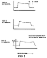
- ECP intelligence is in the real time correction of the varying coefficient of friction, between the brake shoe and the wheel, that occurs during a stop.
- the intelligent ECP system makes retardation force adjustments, through changes in brake cylinder pressure, in order to optimize the stopping performance.
Applications Claiming Priority (2)
| Application Number | Priority Date | Filing Date | Title |
|---|---|---|---|
| US399412 | 1995-03-06 | ||
| US09/399,412 US20030200020A1 (en) | 1999-09-20 | 1999-09-20 | Method of and an apparatus for enhancing the braking efficiency of a railway freight train consist |
Publications (2)
| Publication Number | Publication Date |
|---|---|
| EP1084922A2 true EP1084922A2 (fr) | 2001-03-21 |
| EP1084922A3 EP1084922A3 (fr) | 2003-07-23 |
Family
ID=23579411
Family Applications (1)
| Application Number | Title | Priority Date | Filing Date |
|---|---|---|---|
| EP00117259A Withdrawn EP1084922A3 (fr) | 1999-09-20 | 2000-08-16 | Système de freinage pour un train de wagons ferroviaires |
Country Status (4)
| Country | Link |
|---|---|
| US (1) | US20030200020A1 (fr) |
| EP (1) | EP1084922A3 (fr) |
| CA (1) | CA2317829C (fr) |
| MX (1) | MXPA00009230A (fr) |
Cited By (1)
| Publication number | Priority date | Publication date | Assignee | Title |
|---|---|---|---|---|
| IT201800005948A1 (it) * | 2018-06-01 | 2019-12-01 | Procedimento di gestione della frenatura in una condizione di aderenza degradata per un treno. |
Families Citing this family (6)
| Publication number | Priority date | Publication date | Assignee | Title |
|---|---|---|---|---|
| BRPI0718148B1 (pt) * | 2006-10-06 | 2019-01-22 | New York Air Brake Corp | controlador de locomotiva |
| US7765859B2 (en) * | 2008-04-14 | 2010-08-03 | Wabtec Holding Corp. | Method and system for determining brake shoe effectiveness |
| DE102011113093A1 (de) * | 2011-09-09 | 2013-03-14 | Knorr-Bremse Systeme für Schienenfahrzeuge GmbH | Bremswirkungsbestimmung für ein Schienenfahrzeug |
| US8924117B2 (en) | 2012-05-04 | 2014-12-30 | Wabtec Holding Corp. | Brake monitoring system for an air brake arrangement |
| US9020667B2 (en) | 2012-06-11 | 2015-04-28 | Wabtec Holding Corp. | Empty-load device feedback arrangement |
| CN112793553B (zh) * | 2021-01-28 | 2023-06-27 | 中铁四局集团第五工程有限公司 | 一种刹防系统及控制方法 |
Citations (5)
| Publication number | Priority date | Publication date | Assignee | Title |
|---|---|---|---|---|
| US3819004A (en) * | 1971-06-11 | 1974-06-25 | Co Des Freins Et Signaux Westi | Method and apparatus for preventing wheel slip |
| US4321677A (en) * | 1979-02-16 | 1982-03-23 | Hitachi, Ltd. | Anti-skid control device |
| US4402047A (en) * | 1980-12-16 | 1983-08-30 | General Signal Corporation | Computerized brake control system |
| CH648795A5 (en) * | 1979-12-20 | 1985-04-15 | Oerlikon Buehrle Ag | Anti-slip device for rail vehicles |
| US4783127A (en) * | 1985-10-21 | 1988-11-08 | General Motors Corporation | Anti-lock brake control system |
-
1999
- 1999-09-20 US US09/399,412 patent/US20030200020A1/en not_active Abandoned
-
2000
- 2000-08-16 EP EP00117259A patent/EP1084922A3/fr not_active Withdrawn
- 2000-09-08 CA CA002317829A patent/CA2317829C/fr not_active Expired - Fee Related
- 2000-09-20 MX MXPA00009230A patent/MXPA00009230A/es unknown
Patent Citations (5)
| Publication number | Priority date | Publication date | Assignee | Title |
|---|---|---|---|---|
| US3819004A (en) * | 1971-06-11 | 1974-06-25 | Co Des Freins Et Signaux Westi | Method and apparatus for preventing wheel slip |
| US4321677A (en) * | 1979-02-16 | 1982-03-23 | Hitachi, Ltd. | Anti-skid control device |
| CH648795A5 (en) * | 1979-12-20 | 1985-04-15 | Oerlikon Buehrle Ag | Anti-slip device for rail vehicles |
| US4402047A (en) * | 1980-12-16 | 1983-08-30 | General Signal Corporation | Computerized brake control system |
| US4783127A (en) * | 1985-10-21 | 1988-11-08 | General Motors Corporation | Anti-lock brake control system |
Cited By (3)
| Publication number | Priority date | Publication date | Assignee | Title |
|---|---|---|---|---|
| IT201800005948A1 (it) * | 2018-06-01 | 2019-12-01 | Procedimento di gestione della frenatura in una condizione di aderenza degradata per un treno. | |
| WO2019229709A1 (fr) * | 2018-06-01 | 2019-12-05 | Faiveley Transport Italia S.P.A. | Procédé de gestion du freinage dans des conditions d'adhérence dégradées destiné à un train |
| US11878671B2 (en) | 2018-06-01 | 2024-01-23 | Faiveley Transport Italia S.P.A. | Method for managing braking in a degraded adhesion condition for a vehicle system |
Also Published As
| Publication number | Publication date |
|---|---|
| CA2317829A1 (fr) | 2001-03-20 |
| EP1084922A3 (fr) | 2003-07-23 |
| MXPA00009230A (es) | 2002-08-20 |
| US20030200020A1 (en) | 2003-10-23 |
| CA2317829C (fr) | 2005-02-15 |
Similar Documents
| Publication | Publication Date | Title |
|---|---|---|
| US5927822A (en) | Freight brake control using train net braking ratio | |
| US5820226A (en) | Freight brake control for uniform car deceleration | |
| US5785392A (en) | Selectable grade and uniform net shoe force braking for railway freight vehicle | |
| EP0827886B1 (fr) | Système de contrôle pour système de freinage dépendant de la charge | |
| CA1327236C (fr) | Systeme de commande de freinage pour train routier | |
| US6435624B1 (en) | Railway locomotive brake controller | |
| EP1129919A2 (fr) | Dispositif de commande de freinage pour locomotive de chemin de fer | |
| AU720584B2 (en) | Brake pipe sensing unit | |
| AU603314B2 (en) | Tractor-trailer brake control system | |
| CA2203603C (fr) | Unite de commande de freinage pneumatique combinee | |
| WO2000024625A3 (fr) | Systeme de freinage pour vehicule sur rails | |
| CN102143868A (zh) | 电气动制动装置及其运行方法 | |
| CA2363462C (fr) | Dispositif electronique de detection d'effort de freinage d'urgence | |
| CA2203606C (fr) | Module de veille automatique du freinage | |
| US6820944B2 (en) | Digital multi-point electronic load weigh system | |
| EP1084922A2 (fr) | Système de freinage pour un train de wagons ferroviaires | |
| US6971488B1 (en) | Simplified truck mounted brake system | |
| US5740029A (en) | Software algorithm providing dynamic configuration of dead band control criteria within a micro based real time process control environment | |
| US6375281B1 (en) | Brake torque regulation for vehicles | |
| CA1265562A (fr) | Systeme de commande-regulation du freinage sur locomotive | |
| CA1191880A (fr) | Soupape-relais | |
| JPH05294237A (ja) | 列車ブレーキ分散制御方法 | |
| AU761777B2 (en) | Freight brake control for uniform car deceleration | |
| GB2133099A (en) | Train brake control system |
Legal Events
| Date | Code | Title | Description |
|---|---|---|---|
| PUAI | Public reference made under article 153(3) epc to a published international application that has entered the european phase |
Free format text: ORIGINAL CODE: 0009012 |
|
| AK | Designated contracting states |
Kind code of ref document: A2 Designated state(s): AT BE CH CY DE DK ES FI FR GB GR IE IT LI LU MC NL PT SE |
|
| AX | Request for extension of the european patent |
Free format text: AL;LT;LV;MK;RO;SI |
|
| PUAL | Search report despatched |
Free format text: ORIGINAL CODE: 0009013 |
|
| AK | Designated contracting states |
Designated state(s): AT BE CH CY DE DK ES FI FR GB GR IE IT LI LU MC NL PT SE |
|
| AX | Request for extension of the european patent |
Extension state: AL LT LV MK RO SI |
|
| 17P | Request for examination filed |
Effective date: 20031222 |
|
| AKX | Designation fees paid |
Designated state(s): DE FR GB IT |
|
| 17Q | First examination report despatched |
Effective date: 20040317 |
|
| STAA | Information on the status of an ep patent application or granted ep patent |
Free format text: STATUS: THE APPLICATION HAS BEEN WITHDRAWN |
|
| 18W | Application withdrawn |
Effective date: 20040904 |