EP1083289A1 - Dispositif de liaision mécanique pour système d'attache d'éléments sur une structure porteuse - Google Patents
Dispositif de liaision mécanique pour système d'attache d'éléments sur une structure porteuse Download PDFInfo
- Publication number
- EP1083289A1 EP1083289A1 EP00402452A EP00402452A EP1083289A1 EP 1083289 A1 EP1083289 A1 EP 1083289A1 EP 00402452 A EP00402452 A EP 00402452A EP 00402452 A EP00402452 A EP 00402452A EP 1083289 A1 EP1083289 A1 EP 1083289A1
- Authority
- EP
- European Patent Office
- Prior art keywords
- rod
- axis
- connection device
- mechanical connection
- plate
- Prior art date
- Legal status (The legal status is an assumption and is not a legal conclusion. Google has not performed a legal analysis and makes no representation as to the accuracy of the status listed.)
- Granted
Links
- 239000011521 glass Substances 0.000 claims abstract description 28
- 238000006073 displacement reaction Methods 0.000 claims abstract description 9
- 239000000463 material Substances 0.000 claims description 15
- 230000002093 peripheral effect Effects 0.000 claims description 14
- 238000013519 translation Methods 0.000 claims description 9
- 230000001629 suppression Effects 0.000 claims description 5
- 238000012217 deletion Methods 0.000 claims description 3
- 230000037430 deletion Effects 0.000 claims description 3
- 238000010079 rubber tapping Methods 0.000 claims 1
- 230000008878 coupling Effects 0.000 abstract 1
- 238000010168 coupling process Methods 0.000 abstract 1
- 238000005859 coupling reaction Methods 0.000 abstract 1
- 238000000034 method Methods 0.000 description 7
- 238000004519 manufacturing process Methods 0.000 description 3
- 238000003825 pressing Methods 0.000 description 3
- 239000003351 stiffener Substances 0.000 description 3
- 240000008042 Zea mays Species 0.000 description 2
- 230000000712 assembly Effects 0.000 description 2
- 238000000429 assembly Methods 0.000 description 2
- 230000000295 complement effect Effects 0.000 description 2
- 238000010586 diagram Methods 0.000 description 2
- 239000002184 metal Substances 0.000 description 2
- 238000012986 modification Methods 0.000 description 2
- 230000004048 modification Effects 0.000 description 2
- 210000000056 organ Anatomy 0.000 description 2
- 229920003023 plastic Polymers 0.000 description 2
- BASFCYQUMIYNBI-UHFFFAOYSA-N platinum Chemical compound [Pt] BASFCYQUMIYNBI-UHFFFAOYSA-N 0.000 description 2
- 229920001296 polysiloxane Polymers 0.000 description 2
- 239000005361 soda-lime glass Substances 0.000 description 2
- 239000000758 substrate Substances 0.000 description 2
- 241001080024 Telles Species 0.000 description 1
- 241001639412 Verres Species 0.000 description 1
- 238000005452 bending Methods 0.000 description 1
- 230000005540 biological transmission Effects 0.000 description 1
- 239000000919 ceramic Substances 0.000 description 1
- 239000011248 coating agent Substances 0.000 description 1
- 238000000576 coating method Methods 0.000 description 1
- 238000010276 construction Methods 0.000 description 1
- 230000000694 effects Effects 0.000 description 1
- 229920001971 elastomer Polymers 0.000 description 1
- 239000000806 elastomer Substances 0.000 description 1
- 229940082150 encore Drugs 0.000 description 1
- 238000011065 in-situ storage Methods 0.000 description 1
- 238000009434 installation Methods 0.000 description 1
- 238000005259 measurement Methods 0.000 description 1
- 210000004417 patella Anatomy 0.000 description 1
- 229920002037 poly(vinyl butyral) polymer Polymers 0.000 description 1
- 125000006850 spacer group Chemical group 0.000 description 1
- 229910001220 stainless steel Inorganic materials 0.000 description 1
- 239000010935 stainless steel Substances 0.000 description 1
Images


Classifications
-
- E—FIXED CONSTRUCTIONS
- E06—DOORS, WINDOWS, SHUTTERS, OR ROLLER BLINDS IN GENERAL; LADDERS
- E06B—FIXED OR MOVABLE CLOSURES FOR OPENINGS IN BUILDINGS, VEHICLES, FENCES OR LIKE ENCLOSURES IN GENERAL, e.g. DOORS, WINDOWS, BLINDS, GATES
- E06B3/00—Window sashes, door leaves, or like elements for closing wall or like openings; Layout of fixed or moving closures, e.g. windows in wall or like openings; Features of rigidly-mounted outer frames relating to the mounting of wing frames
- E06B3/54—Fixing of glass panes or like plates
- E06B3/5436—Fixing of glass panes or like plates involving holes or indentations in the pane
Definitions
- the present invention relates to fastening systems in at least one point of elements such as panels, in particular of fragile material, in particular glass, comprising, at each attachment point, a device for fixed attachment to the element carried and provided with a hanging rod substantially perpendicular to the surface of the element and intended to be mounted on a mounting member fixed to the supporting structure.
- the fastening device is such that it can allow the worn element to bend slightly compared to its support structure, which is the case of a pendulum or patella.
- glazed façades made up of Attached Exterior Glazing (VEA).
- VSA Attached Exterior Glazing
- These glazing generally includes glass panels of any type: monolithic, laminated, multiple glazing, at least one wall of which can itself be flaky, etc. They are fitted with fasteners or of attachment which generally have a rod in common hooking projecting from one side, perpendicular or substantially perpendicular to the glass panel, mounted on the panel by a connecting means of any type, in particular pendulum, ball joint, by bolts, etc.
- the connecting means is such that the other side of the panel opposite the rod has no element extending beyond the front.
- the height of these glass panels can reach 6 meters, the density of the glass being of the order of 2.5, and a hanging point being arranged at each corner of the panel, one can imagine the difficulties of mounting a like glass facade on existing supports which are not always perfectly plans as well as the difficulties that may arise during the time due to the differences in expansion between the glass panels and support structures.
- the applicant company sought means of mechanical connection between the attachment rods of the fixing devices and the mounting members generally attached to support structures, with the objective that such means that the elements of glass or other fragile material remain in their inertia plan and that there is no addition of prestresses related to relative movements due to the aforementioned differences in expansion, so that the material retains all of its mechanical properties.
- a connecting device mechanical between hooking rod and mounting member, which ensures break in the transmission of forces, and which allows the rod, whose position is adjustable during assembly along its axis, to have a certain number of degrees of freedom in a plane perpendicular to its axis.
- the linkage device mechanics according to the invention also makes it possible to choose the number of degrees of freedom left at each attachment point, because the constraints are not the same for high points and low points in a system.
- This mechanical connection device allows refined management of relative movements in a carpentry or facade assembly comprising elements made of glass or other fragile material, in particular ceramic, which situation are subject to significant efforts, whether these are elements of essentially flat shape like plates or panels, but also volume elements such as beams or columns.
- a mechanical connection device which is suitable to be mounted between said rod and said mounting member, which comprises a means for adjusting, during assembly, the position of said rod along its axis, and which is arranged to authorize, once the device is mounted, a displacement of said rod perpendicular to its axis, within limits fixed, with the possibility of restriction going as far as deletion, when mounting and / or once the device is mounted, a degree of freedom or both degrees of freedom of said displacement, at the same time as is ensured, in the event of deletion of this or these degrees of freedom, a final adjustment of the position of said rod along the axis or axes on which or which the degree of freedom of the move has been deleted.
- the rod carries a tray perpendicular to the axis of said rod, said plate being guided during its displacement along its plane, the displacement of the rod perpendicular to its axis being limited by a peripheral part which is carried by the mounting and with which is likely to cooperate at least one stop whose the distance from said peripheral part is adjustable, ensuring the restriction going until the suppression of the degree or degrees of freedom in the plane perpendicular to the axis of said rod.
- the plate is mounted movable perpendicular to the axis of the rod in all directions; in particular, the plate can be mounted to slide in particular at its periphery between two walls carried by the mounting member.
- the plate is mounted displaceable perpendicular to the axis of the rod in one or two directions corresponding to the degree or degrees of freedom of movement of the rod; in particular, the plate can be mounted movable in the horizontal direction and in the vertical direction, the element in particular of fragile material being mounted vertically, the plate then advantageously constituting one of the end trays of a set of trays of the Oldham joint type arranged to surround the rod.
- the mechanical connection device comprises a means for adjusting the position of the rod capable of adjusting said position from a continuous set of positions along the axis or axes of suppression of the degrees of freedom.
- each stop can be formed by the head of a screw-shoe, the threaded rod cooperates with a threaded hole made in the mounting member, the adjustment of this screw-pad or of each of these screw-pads allowing a restriction of the movement of the associated plate, therefore of the rod, within the limits chosen, in one or two directions corresponding to the degree or degrees of freedom of movement of the rod.
- the mechanical connection device comprises a means capable of adjusting the position of the rod along its axis continuously within an interval of lengths determined.
- the adjustment, during assembly, of the position of the rod along its axis can be done by screwing, on the mounting member or on an integral part of said mounting member or on a part which cooperates with the mounting member mounting but whose position along the axis of the rod remains fixed, in one piece integral in translation with said rod.
- the plate can then have a tapped central opening cooperating with a region outer threaded with a sleeve in which the rod is adapted to come to penetrate during assembly until it reaches the stop in the position set along its axis according to the chosen position of the sleeve.
- the other end plate of the assembly of the Oldham seal type can then be housed in the cavity of a nut having an external thread capable of cooperating with a thread made in a peripheral wall opposite the mounting member.
- the mounting member can advantageously form or carry a housing of the device according to the invention, this being then in the form of a cage having an axial opening with an axis parallel to the axis of the rod in the mounted position, said cage containing the elements of adjustment and fixing of the position of said rod along its axis, and the elements for adjusting said rod perpendicular to its axis.
- the housing can advantageously be formed by the assembly of two plates having each a central opening, between which the plate is mounted at sliding, the peripheral edge of one of the plates having at least a tapped opening for the passage of a screw-pad.
- the housing can advantageously be formed by a ring of axis parallel to the axis of the rod in mounting position, the ring having, in the vicinity of one of its ends at least one tapped opening for the passage of a screw-shoe and its other end, a thread intended to cooperate with the thread of the nut for adjusting the position of the rod along its axis.
- the present invention also relates to a mounting member intended to be fixed on a supporting structure and comprising at least one device for mechanical connection with a hooking rod forming part of a fixing carried by an element in particular of fragile material, such as glass, in order to constitute in particular a glazed facade of attached external glazing, said connecting device being as defined above.
- Said mounting member may, in a known manner for glass facades, wear one to four arms depending on whether it is intended to cooperate in mounting respectively one to four elements, in particular of fragile material.
- the mounting member comprises, in the case where the stops are constituted by the heads of screw-shoes, as accessories, a set of screw-shoes associated with each link device.
- the cage can therefore present independently, all the pieces that make it up contained in said housing. This then includes means making it possible to fix the cage on the mounting device.
- the housing is itself arranged to be able to be fixed directly on the supporting structure.
- the present invention therefore also relates to a cage such that defined above, the housing of which is designed to be fixed to the structure carrier directly or by intermediate fixing of the housing on a mounting, a set of screw-pads being associated with said cage as accessories, for mounting a structure of elements, in particular of fragile material, such as than glass, in order to constitute in particular a glazed facade of Vitrages Attached exteriors.
- the adjustment possibilities offered by the device according to the invention can make it a mounting accessory in other parts of the system for example to adjust the mounting position a mounting member on the structure.
- the present invention finally relates to facades or glazed walls fitted with mounting devices as defined above or cages such as defined above.
- the mounting members 4 include each a hub 5 pierced with a fixing hole 6 of the member in question at the load-bearing structure.
- the hubs 5 externally carry one to four arms 7 depending on whether the member 4 in question is intended to cooperate in the mounting of respectively one to four glazing 1.
- the arms 7, which are all equal, are all tilted forward if we look at Figure 1 and they each carry, at their free end, a cylindrical ring 8 ( Figure 3) with an axis parallel to the axis central of the fixing hole 6 of the hub 5.
- the arms 7 are arranged with an angular orientation such that the axes of the rings 8 coincide with the axes of the attachment points 3 of the glazing 1, as illustrated by the figure 1.
- the axis of the rings 8 (or of the attachment points 3) is called also the z axis.
- Each of these rings 8 constitutes the housing of a cage link according to the present invention, which cooperates with both the associated mounting 4 and with a rod for attaching the device for fixing the panel 1 along the axis of the corresponding attachment point 3.
- FIG 2 there is shown an assembly diagram comprising a glazing panel V, a stiffening glass panel R and elements of framework O, with interposition of cages C according to the present invention.
- This schematic representation of Figure 2 mainly aims to indicate on what types of systems can be interposed a connecting cage according to the invention. It illustrates the possibility of orienting these cages in all directions, the adjustment along the z axis for a panel, as will be described below, which can transform into an adjustment along the x axis for a panel arranged transversely. Multiple variants are possible from the figure 2, by removing one or the other of the glazing and the stiffener, or by replacing it by another building element made of fragile material.
- FIG. 3 a device for fixing a glazing 1 to a mounting member 4 at a point attachment 3.
- the glazing 1 shown here is a monolithic glazing. It has a substrate 9 of soda-lime-silica glass, preferably with a thickness of at least minus 8 mm, for example 12, 15 or 19 mm, drilled with a countersunk hole 10 in each of its corners. This hole 10 is crossed by a metal screw 11, also milled, the head of which is flush with the face 12 of the glazing intended for be on the "outside" side of the facade once the glazing is attached to the facade. A flexible collar-seal 13 is interposed between the screw 11 and the wall of the hole 10 so avoid direct glass-to-metal contact.
- the screw 11 is also hollowed out with a cylindrical cavity 14. In this cavity 14, is housed with a certain play the head 15 of a rod element 16, the other end of which cooperates with the elements which will be described below of a connection cage 17 including the ring 8 corresponding to the mounting member 4 constitutes the housing.
- the head 15 of the rod element 16 has a flat front face which comes lean against the bottom of the cylindrical cavity 14 with the interposition of a flexible seal 18, advantageously made of elastomer with Shore hardness by example of about 50. Its lateral face of revolution is the association of two cone portions via an annular portion. Head 15 is held in place in the cavity 14 by a clamping piece 19, a washer 20 of a material similar to that of seal 18 being interposed between the rear face of the head 15 and the clamping piece 19.
- a certain clearance is maintained between the cavity 14 and the head 15 by a choice of cavity diameter 14 slightly greater than that of the annular zone of the head 15 and by the aforementioned flexible materials 18 and 20.
- the movement of the rod 16 is authorized by the internal profile of the clamping piece 19, having a central opening of larger diameter than that of the cylindrical part opposite the rod 16.
- the assembly is tightened by a nut 21 which is screwed onto the screw 11 and the clamping piece 19, coming to bear against the face 22 of the substrate 9 with interposition of a flexible washer 23.
- the glazing 1 has been attached, as shown in FIG. 3, according to a substantially vertical plane, its point or its support area P on the device fixing which has just been described, is situated approximately on the zone annular of the head 15, in the upper part, and it is around this point or this support zone P that the glazing 1 will be able to tilt so pendulum, and in all directions, the amplitude of the authorized bending - usually set to a few degrees - the glazing being controlled by play between the head 15 and the cavity 14 and by the capacity to compress the seal 18 and of the washer 20.
- the glazing 1 can thus bend slightly, either in the event of winds violent, either to take into account the tolerances regarding its positioning by in relation to the supporting structure.
- EP-B-0 655 543 Such a fixing device, known as pendulum, is described in the patent.
- European patent EP-B-0 655 543 are also described devices for pendulum fixings applied to double glazing and laminated glazing. he it goes without saying that all these devices can be used interchangeably, in particular in all the embodiments and variants described in EP-B-0 655,543, since the present invention is not limited to glazing monolithic.
- It also includes multiple glazing of the double glazing type, in which different glass plates are assembled by through a gas slide using a peripheral seal, as well as the laminated glazings, such as those composed of a silica-soda-lime glass plate float called "interior”, assembled with another glass plate of same nature, called “exterior”, by means of an intermediate sheet made of plastic of the polyvinyl butyral type.
- Multiple glazing can also include at least one sheet of laminated type glass.
- the present invention is not limited to devices pendulum fixing and applies equally to all types of devices fastening as soon as these comprise a rod intended to be connected to the supporting structure. Mention may be made, among others, of the fastening devices ball joint as described in European patent applications EP-A-0 201 212 and EP-A-0 506 522, in German patent application DE-A-4 325 024, to eccentric circular rings, as described in EP-A-0 506 522, or anchor bolts screwed into fixing fittings, as described in European patent applications EP-A-0 552 101 and 0 595 062.
- the present invention can be applied to fixing devices in which the fixing rod is carried by the supporting structure, as this is the case for systems in which the glazing is maintained by pinching (French patent FR-B-2 739 406).
- the cylindrical symmetrical rod 16 has, in its projecting part, at a distance from the glazing fixing device 1, on the right when look at Figure 3, a gradual increase in its section (at 29) until a section part (30) having the shape of a flattened circle to form two flat horizontal surfaces 31, then a gradual decrease in its section (at 32) until it returns to its initial diameter, the rod 16 ending then by a threaded part 33.
- the rear wall 56 of the nut 27 also has at its periphery several blind holes 57 (at least two) regularly spaced, in which we can come and introduce an appropriate screwing tool the nut 27.
- the side facing the nut 27 has a coating 58 intended to improve the sliding.
- a nut 59 cooperating with the threaded end of the rod 16 tightens the assembly by pressing against the support washer 28.
- the ring 8 comprises, in the vicinity of its free edge, four radial holes, namely two diametrically opposed tapped holes 60 along the y-axis ( Figure 3) and two diametrically opposed tapped holes 61 along the x-axis ( Figures 8 and 10), the holes 60 and 61 being arranged to find opposite flats 34-35 and 36-37 respectively of the plate 24.
- the mechanical connection device according to the invention is moreover optionally supplemented by two flexible seals 62 and 63.
- the seal 62 has a generally annular shape and is fixed by its outer border to the internal free border of the ring 8 and by its internal border on the face front 40 of the plate 24.
- the seal 63 it has the shape of a bellows, being fixed, by one of its edges, to the front edge of the nut attachment 21 of the rod 16 and, by its other border, to the front border of the opening 38 of the plate 24.
- the seals 62 and 63 can be fixed by snapping for example into grooves provided for this purpose on the elements respectively 8 and 24, and 24 and 21.
- the seals 62 and 63 protect the cage 17 in position of use.
- each ring 8 of a mounting member 4 we just set up elements 24 to 27 to thus constitute the mechanical connection device or cage 17, the plates 24, 25 and 26 being nested successively in one the others, the plate 26 being received in the interior cavity of the nut 27, and this the latter being screwed onto the ring 8.
- the latter forms the housing of said cage 17.
- the contact surfaces between the plate 26 and the nut 27 are advantageously treated to ensure sliding when adjusting the position of the nut 27 along the z axis.
- Temporary restraint may be planned.
- the different mounting devices 4 each equipped with the number corresponding cages 17 are fixed on the supporting structure.
- a preset of the position of the nuts 27 along the z axis can be carried out before or after fixing the mounting members 4 on the supporting structure.
- the panels 9 can be provided with seals flexible 63, similar to seals 62, which are for example snapped in beforehand in the front walls 40 of the plates 24 of the cages 17, and that one snaps onto the free edge of the nuts 21 of the fastening devices said panels 9.
- the tightness of the assemblies is therefore ensured by the seals 62 and 63, the seals 63 pressing against the walls 40, or even against the seals 62 according to the fixing position of the latter on said walls 40.
- the assembly method which has just been described is not intended to be limiting: can for example consider equipping the rods 16 with the plates 24 to 26 with use of suitable retaining means, and place these assemblies in the rings 8 of the mounting members 4, whether or not provided with screws 27.
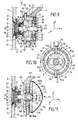
- the plate 24 can move freely in translation along the x axis, the tongue 49 sliding in the groove 46 ( Figure 7), and the plate 24 - which follows the plate 25 in its displacement along the x axis due to the embedding of the bar 41 in the groove 45 - can move freely in translation along the y axis, said strip 41 sliding in said groove 45 ( Figure 8). Thanks to the supports at 31 against the wall delimiting the bore 38 of the plate 24, any possibility of relative rotation between the rod 16 and the plate is prevented 24.
- assembly (II) adjustment along the z and y axes and freedom of translation along the x axis.
- the cage 17 thanks to the screwing allows adjustment end of attachment position 3 in three dimensions.
- screw-pads 64 and / or 65 do not necessarily come to bear against the corresponding flats of the plate 24, but that their heads respectively 64 a and 65 a remain at a distance chosen each time by the fitter to limit the movement of the attachment point 3 along the axes of y and x respectively.
- the flats of the plates 24 can be treated to constitute sliding surfaces of the heads 64 a and 65 has screw-pads respectively 64 and 65.
- the parts cooperating in a sliding of the plates 24 to 26 can be advantageously treated to constitute sliding surfaces.
- the plates 25 and 26, which take up the forces less than the plate 24 and rather serve as a sliding surface in this embodiment, could also be made of plastic.
- the glass panel 9 and its associated fixing devices provided with their projecting rods 16 are the same as those of the first embodiment and therefore bear the same reference figures. The only difference is that the end part of the rods 16 from the frusto-conical parts 32 is more short.
- the mounting member 104 intended to be fixed to the support structure differs from member 4 of the first embodiment in that each of the arm 107 which he carries no longer ends in a ring, but in a eyelet constituted by a circular bottom 166 comprising a central opening 167, with an axis coinciding with the axis of the corresponding attachment point 3 in the mounting position shown.
- the circular bottom 166 is folded square on its entire border 168, opposite the glazing 1 or panel 9 in the position of mounting.
- three tapped holes 169 are made, the axes are arranged radially, one - the one seen in Figure 11 - along the y axis, and the other two, along the x axis.
- These tapped holes 169 are used for passage of screw-pads 170 comprising heads 170a, mounted in the same way as the screw-pads 64 and 65 of the first embodiment.
- the content of the cage 17 of the first embodiment is here simplified to the point of having only one circular plate 171.
- This plate 171 has a peripheral wall comprising three flats 172, each being associated with a screw-pad 170, in the same way as the flats 34 to 37 of the plate 24 were associated with screw-pads 64 and 65 of the first mode of production.
- the tray 171 has a circular opening tapped central unit 173.
- the housing 108 of the cage 117 is constituted by the front plate 166 supplemented by a rear plate 166 a having a central opening 167 has the same diameter as the opening 167 and coming to be placed facing the latter in the mounting position.
- the front outer edge of the plate 166 a has a notch 166 b which receives the edge 168 in the mounting position, the side wall of the plate 166 a then coming in the extension of the outer wall of the edge 168.
- the plate 166 a is fixed to this border 168 by screws (not shown) or by any other means.
- the end part of the rod 16 between the frustoconical part 32 and the near its free end receives a cylindrical sleeve 174, the external wall has, except in its rear end part, a thread 175 intended to cooperate with the thread of the opening 173 of the plate 171.
- the internal wall of the sleeve 174 is shaped to allow it to come thread on the rod 16 by the end thereof, and come into abutment against the conical part 32.
- the device shown in this figure 11 is completed by a cover rear 176 in the form of a spherical cap which is forced into place by its free ring-shaped border against the external lateral wall of the plate 166a.
- This device is mounted, for example, as follows: the cages 117 associated with the mounting members 104 are formed by putting in place the screw-shoes 170, the plate 171 receiving the sleeve 174 by screwing, then the closure plate 166 a .
- the screw-pads 170 ensure the correct orientation of the flats 172 during assembly. We can then ensure an adjustment of the future position of the rod 16 along the axis z by acting on the sleeve 174 by screwing from its rear end wall.
- the panel 9 is then presented with its projecting rod 16 through the opening of the sleeve 174, until the frustoconical part 32 abuts against the corresponding internal wall of the inlet opening of the sleeve 171.
Landscapes
- Engineering & Computer Science (AREA)
- Civil Engineering (AREA)
- Structural Engineering (AREA)
- Load-Bearing And Curtain Walls (AREA)
Abstract
Description
- la figure 1 est une vue schématique partielle d'une façade vitrée VEA, des arrachements laissant voir les organes de montage de ces vitrages sur la structure porteuse ;
- la figure 2 est un schéma de modélisation montrant un vitrage d'un système VEA destiné à être stabilisé par un élément raidisseur formé d'une plaque de verre, les organes de fixation vitrage-structure porteuse, raidisseur-vitrage et raidisseur-structure porteuse incorporant chacun une cage de liaison conforme à la présente invention ;
- la figure 3 est, à échelle agrandie, une vue partielle en coupe transversale d'un vitrage de la figure 1, ladite coupe étant effectuée selon l'axe d'un élément de fixation dudit vitrage à l'organe de montage associé, avec interposition d'une cage de liaison conforme à un premier mode de réalisation de l'invention et montée selon le mode de montage (I) tel que défini ci-après ;
- la figure 4 est une vue en perspective éclatée des différentes pièces composant ladite cage ;
- la figure 5 est une vue en coupe selon V-V de la figure 3 ;
- la figure 6 est une vue analogue à la figure 3, dans une position dans laquelle l'axe de l'élément de fixation du vitrage s'est déplacé au cours du temps ;
- les figures 7 et 8 sont des vues en coupe selon respectivement VII-VII et VIII-VIII de la figure 6 ;
- la figure 9 est une vue analogue à la Figure 3, excepté que la cage de liaison est montée selon le mode de montage (II) tel que défini ci-après ;
- la figure 10 est une vue en coupe selon X-X de la figure 9, deux vis-patins supplémentaires étant représentées en trait mixte, lesquelles sont utilisées dans un mode de montage (III) ;
- la figure 11 est une vue analogue aux figures 3 et 9, avec une cage de liaison conforme à un second mode de réalisation de la présente invention.
- trois plateaux 24, 25, 26 qui forment ensemble un système de type joint d'Oldham ;
- un écrou de réglage 27 ; et
- une rondelle d'appui 28,
- Le plateau 24 a la forme générale d'un disque dont la paroi périphérique comporte quatre méplats régulièrement espacés, à savoir deux méplats horizontaux 34, 35 et deux méplats verticaux 36, 37 si l'on regarde la figure 4. Le plateau 24 comporte un perçage axial 38 débouchant, dans sa paroi arrière 39 si l'on regarde la figure 4 suivant une partie cylindrique de section légèrement supérieure à la section circulaire de la partie d'extrémité de la tige 16, et débouchant, dans sa paroi avant 40, suivant une partie de section oblongue dont le grand axe est disposé horizontalement, la partie cylindrique et la partie de section oblongue étant reliées par une partie conique destinée à s'adapter étroitement autour des parties 30 et 32 de la tige 16, comme on peut le voir en position de montage sur la figure 3. Le perçage avant est ici de forme oblongue notamment pour des raisons de commodité de fabrication du plateau 24 et pourrait affecter une autre forme.
- Le plateau 25 a la forme générale d'un disque de même diamètre que le plateau 24. Il comporte une ouverture circulaire centrale 42 de diamètre très supérieur au diamètre de la tige 16 dans sa partie cylindrique. Sa paroi avant 43 et sa paroi arrière 44, si l'on regarde la figure 3, comportent chacune une rainure diamétrale, respectivement 45 et 46, la rainure 45 étant disposée verticalement et la rainure 46 étant disposée horizontalement. Chacune des rainures 45 et 46 est en deux parties compte tenu de l'ouverture 42. La section transversale, sensiblement carrée, de la rainure 45, est complémentaire de celle de la barrette 41 du plateau 24, ladite barrette 41 pouvant coulisser dans ladite rainure 45.
- Le plateau 26 se présente sous la forme générale d'un disque de même dimension que le plateau 25, avec une ouverture circulaire centrale 47 de même dimension que l'ouverture 42 du disque 25. Sa paroi avant 48 comporte, en saillie, une languette diamétrale 49, disposée horizontalement et se trouvant être en deux parties compte tenu de l'ouverture 47. La section transversale, sensiblement carrée, de la languette 49 est complémentaire de celle de la rainure 46, ladite languette 49 pouvant coulisser dans celle-ci.
- L'écrou de réglage 27 est constitué par une platine 50 comportant une ouverture centrale 51 de même diamètre que les ouvertures 42 et 47, ladite platine 50 présentant un rebord périphérique 52 de hauteur telle que ledit écrou 27 est susceptible de recevoir au moins partiellement le plateau 26, la bordure périphérique annulaire avant 53 de l'écrou 27 venant alors se situer avantageusement dans le même plan que la paroi avant 48 du plateau 26, mais aussi éventuellement en retrait ou encore éventuellement en saillie autour du plateau 25 (mais en retrait de la rainure 45). Par ailleurs, la paroi périphérique du rebord 52 comporte un filetage 54 destiné à coopérer avec un taraudage 55 porté par la bague 8 dans sa partie d'extrémité qui sera située à l'opposé du vitrage 1 en position de montage. Ce taraudage 55 s'étend sur une distance plus grande que le filetage 54.
- un premier plateau déplaçable dans une première position (par exemple horizontale) présentant une ouverture centrale oblongue disposée perpendiculairement à la première direction (par exemple verticalement) et dont la largeur correspond au diamètre de la tige 16 (qui n'a plus de renflement médian) ; et
- un deuxième plateau plaqué contre le premier et déplaçable dans une deuxième direction (par exemple verticale) présentant une ouverture centrale oblongue disposée perpendiculairement à la deuxième direction (par exemple horizontalement).
Claims (21)
- Dans un système d'attache en au moins un point d'un élément (1 ; 9) notamment de matériau fragile, tel que le verre, sur une structure porteuse, comportant en chaque point d'attache, un dispositif de fixation solidaire de l'élément porté (1 ; 9) et muni d'une tige d'accrochage (16) sensiblement perpendiculaire à la surface de l'élément (9) et destinée à être montée sur un organe de montage (4 ; 104) fixé à la structure porteuse,
un dispositif de liaison mécanique (17 ; 117) qui est apte à être monté entre ladite tige (16) et ledit organe de montage (4 ; 104), qui comporte un moyen permettant le réglage, lors du montage, de la position de ladite tige (16) selon son axe, et qui est agencé pour autoriser, une fois le dispositif monté, un déplacement de ladite tige (16) perpendiculairement à son axe, dans des limites fixées, avec possibilité de restriction allant jusqu'à la suppression, lors du montage et/ou une fois le dispositif monté, d'un degré de liberté ou des deux degrés de liberté dudit déplacement, en même temps qu'est assuré, en cas de suppression de ce ou ces degrés de liberté, un réglage définitif de la position de ladite tige (16) selon l'axe ou les axes sur lequel ou lesquels le degré de liberté du déplacement a été supprimé. - Dispositif de liaison mécanique selon la revendication 1, caractérisé par le fait que la tige (16) porte un plateau (24 ; 171) perpendiculaire à l'axe de ladite tige (16), ledit plateau (24 ; 171) étant guidé lors de son déplacement selon son plan, le déplacement de la tige (16) perpendiculairement à son axe étant limité par une partie périphérique qui est portée par l'organe de montage (4 ; 104) et avec laquelle est susceptible de coopérer au moins une butée (64a ; 65a ; 170a) dont la distance d'avec ladite partie périphérique est réglable, permettant d'assurer la restriction allant jusqu'à la suppression du ou des degrés de liberté dans le plan perpendiculaire à l'axe de ladite tige (16).
- Dispositif de liaison mécanique selon la revendication 2, caractérisé par le fait que le plateau (171) est monté déplaçable perpendiculairement à l'axe de la tige (16) suivant toutes les directions.
- Dispositif de liaison mécanique selon la revendication 3, caractérisé par le fait que le plateau (171) est monté à glissement à sa périphérie entre deux parois (166 et 166a) portées par l'organe de montage (104).
- Dispositif de liaison mécanique selon la revendication 2, caractérisé par le fait que le plateau (24) est monté déplaçable perpendiculairement à l'axe de la tige (16) suivant une ou deux directions correspondant au degré ou aux degrés de liberté du déplacement de la tige (16).
- Dispositif de liaison mécanique selon la revendication 5, caractérisé par le fait que le plateau (24) est monté déplaçable dans la direction horizontale et dans la direction verticale, l'élément (1 ; 9) notamment de matériau fragile étant monté verticalement.
- Dispositif de liaison mécanique selon l'une des revendications 5 et 6, caractérisé par le fait que le plateau (24) constitue l'un des plateaux d'extrémité d'un ensemble de plateaux du type joint d'Oldham (24 - 25 - 26) disposés de manière à entourer la tige (16).
- Dispositif de liaison mécanique selon l'une quelconque des revendications 1 à 7, caractérisé par le fait qu'il comporte un moyen (64 ; 65 ; 170) de réglage de la position de la tige (16) apte à régler ladite position parmi un ensemble continu de positions selon l'axe ou les axes (x,y) de suppression de degré de liberté.
- Dispositif de liaison mécanique selon les revendications 2 et 8, caractérisé par le fait que chaque butée est formée par la tête (64a ; 65a ; 170a) d'une vis-patin (64 ; 65 ; 170), dont la tige filetée coopère avec un trou taraudé (60 ; 61 ; 169) pratiqué dans l'organe de montage (4 ; 104), le réglage de cette vis-patin ou de chacune de ces vis-patins permettant une restriction du déplacement du plateau associé (24 ; 171), donc de la tige (16), dans les limites choisies, selon une ou deux directions correspondant au degré ou aux degrés de liberté de déplacement de la tige.
- Dispositif de liaison mécanique selon l'une quelconque des revendications 1 à 9, caractérisé en ce qu'il comporte un moyen (27) apte à régler la position de la tige (16) selon son axe (z) de façon continue dans un intervalle de longueurs déterminé.
- Dispositif de liaison mécanique selon la revendication 10, caractérisé par le fait que le réglage, lors du montage, de la position de la tige (16) selon son axe s'effectue par vissage, sur l'organe de montage (4) ou sur une pièce solidaire dudit organe de montage (4) ou sur une pièce (171) qui coopère avec l'organe de montage (104) mais dont la position selon l'axe de la tige (16) reste fixe, d'une pièce (27 ; 174) solidaire en translation de ladite tige (16).
- Dispositif de liaison mécanique selon l'une des revendications 3 et 4 et la revendication 11 prises simultanément, caractérisé par le fait que le plateau (171) présente une ouverture centrale taraudée (173) coopérant avec une région extérieure filetée d'un manchon (174) dans lequel la tige (16) est apte à venir pénétrer lors du montage jusqu'à mise en butée dans la position réglée selon son axe d'après la position choisie du manchon (174).
- Dispositif de liaison mécanique selon les revendications 7 et 11 prises simultanément, caractérisé par le fait que l'autre plateau d'extrémité (26) de l'ensemble du type joint d'Oldham est logé dans la cavité d'un écrou (27) présentant un filetage externe (56) susceptible de coopérer avec un taraudage (55) pratiqué dans une paroi périphérique en regard (8) de l'organe de montage (4).
- Dispositif de liaison mécanique selon l'une des revendications 1 à 13, caractérisé par le fait que l'organe de montage (4 ; 104) forme ou porte un boítier (8 ; 108) dudit dispositif, celui-ci se présentant sous la forme d'une cage (17 ; 117) ayant une ouverture axiale d'axe parallèle à l'axe de la tige (16) en position montée, ladite cage (17 ; 117) renfermant les éléments de réglage et de fixation de la position de ladite tige selon son axe, et les éléments de réglage de ladite tige (16) perpendiculairement à son axe.
- Dispositif de liaison mécanique selon les revendications 4, 9, 12 et 14, caractérisé par le fait que le boítier (108) est formé par l'assemblage de deux plaques (166 ; 166a) présentant chacune une ouverture centrale (167 ; 167a), entre lesquelles le plateau (171) est monté à glissement, le rebord périphérique (168) de l'une des plaques (167) présentant au moins une ouverture taraudée (169) pour le passage d'une vis-patin (170).
- Dispositif de liaison mécanique selon les revendications 5, 9, 13 et 14, caractérisé par le fait que le boítier (8) est formé par une bague d'axe parallèle à l'axe de la tige (16) en position de montage, la bague (8) présentant, au voisinage de l'une des ses extrémités, au moins une ouverture taraudée (60 ; 61) pour le passage d'une vis-patin (164 ; 165), et, à son autre extrémité, le taraudage (55) destiné à coopérer avec le filetage (56) de l'écrou (27) de réglage de la position de la tige (16) selon son axe.
- Organe de montage (4 ; 104) destiné à être fixé sur une structure porteuse et comportant au moins un dispositif (17 ; 117) de liaison mécanique avec une tige d'accrochage (16) faisant partie d'un dispositif de fixation porté par un élément (1 ; 9) notamment de matériau fragile, tel que le verre, afin de constituer notamment une façade vitrée de Vitrages Extérieurs Attachés, ledit dispositif de liaison (17 ; 117) étant tel que défini à l'une des revendications 1 à 16.
- Organe de montage, selon la revendication 17, caractérisé par le fait qu'il porte un à quatre bras (7 ; 107) suivant qu'il est destiné à coopérer au montage de respectivement un à quatre éléments (1 ; 9).
- Organe de montage, selon l'une des revendications 17 et 18, comportant au moins un dispositif de liaison (17 ; 117) tel que défini à l'une des revendications 9 à 16 et, en tant qu'accessoires, un jeu de vis-patins (64 ; 65 ; 170) associé à chaque dispositif de liaison (17 ; 117).
- Cage telle que définie à l'une des revendications 14 à 16, dont le boítier (8 ; 108) est agencé pour être fixé sur la structure porteuse directement ou par fixation intermédiaire du boítier sur un organe de montage, un jeu de vis-patins (64 ; 65 ; 170) étant associé à ladite cage (17 ; 117) en tant qu'accessoires, pour le montage d'une structure d'éléments notamment de matériau fragile, tel que le verre, afin de constituer notamment une façade vitrée de Vitrages Extérieurs Attachés.
- Façades ou parois vitrées équipées d'organes de montage tels que définis à l'une des revendications 17 à 19 ou de cages telles que définies à la revendication 20.
Applications Claiming Priority (2)
| Application Number | Priority Date | Filing Date | Title |
|---|---|---|---|
| FR9911226A FR2798953B1 (fr) | 1999-09-08 | 1999-09-08 | Dispositif de liaison mecanique pour systeme d'attache d'elements sur une structure porteuse |
| FR9911226 | 1999-09-08 |
Publications (2)
| Publication Number | Publication Date |
|---|---|
| EP1083289A1 true EP1083289A1 (fr) | 2001-03-14 |
| EP1083289B1 EP1083289B1 (fr) | 2014-04-16 |
Family
ID=9549634
Family Applications (1)
| Application Number | Title | Priority Date | Filing Date |
|---|---|---|---|
| EP20000402452 Expired - Lifetime EP1083289B1 (fr) | 1999-09-08 | 2000-09-06 | Dispositif de liaision mécanique pour système d'attache d'éléments sur une structure porteuse |
Country Status (3)
| Country | Link |
|---|---|
| EP (1) | EP1083289B1 (fr) |
| FR (1) | FR2798953B1 (fr) |
| PT (1) | PT1083289E (fr) |
Cited By (3)
| Publication number | Priority date | Publication date | Assignee | Title |
|---|---|---|---|---|
| EP1516993A1 (fr) * | 2003-09-18 | 2005-03-23 | Stramandinoli S.r.l. | Facade avec panneaux ponctuellement suspendus et système de fenêtre ou porte pour une telle facade |
| US7916220B2 (en) | 2005-06-30 | 2011-03-29 | Qisda Corporation | Fixing structure |
| CN103321538A (zh) * | 2013-06-05 | 2013-09-25 | 浙江瑞明节能科技股份有限公司 | 一种玻璃固定结构 |
Citations (3)
| Publication number | Priority date | Publication date | Assignee | Title |
|---|---|---|---|---|
| EP0555517A2 (fr) * | 1991-07-12 | 1993-08-18 | Giuseppe Passuello | Dispositif pour le maintien de poteaux, montants et similaires pendant la mise en place et le durcissement du mortier |
| EP0663507A2 (fr) * | 1994-01-14 | 1995-07-19 | Josef Gartner & Co. | Moyen de montage pour supporter un panneau |
| DE19703298A1 (de) | 1997-01-30 | 1998-08-06 | Krstin Zlatomir | Punktbefestigungssystem für Flachglasmontage |
-
1999
- 1999-09-08 FR FR9911226A patent/FR2798953B1/fr not_active Expired - Lifetime
-
2000
- 2000-09-06 PT PT00402452T patent/PT1083289E/pt unknown
- 2000-09-06 EP EP20000402452 patent/EP1083289B1/fr not_active Expired - Lifetime
Patent Citations (3)
| Publication number | Priority date | Publication date | Assignee | Title |
|---|---|---|---|---|
| EP0555517A2 (fr) * | 1991-07-12 | 1993-08-18 | Giuseppe Passuello | Dispositif pour le maintien de poteaux, montants et similaires pendant la mise en place et le durcissement du mortier |
| EP0663507A2 (fr) * | 1994-01-14 | 1995-07-19 | Josef Gartner & Co. | Moyen de montage pour supporter un panneau |
| DE19703298A1 (de) | 1997-01-30 | 1998-08-06 | Krstin Zlatomir | Punktbefestigungssystem für Flachglasmontage |
Cited By (4)
| Publication number | Priority date | Publication date | Assignee | Title |
|---|---|---|---|---|
| EP1516993A1 (fr) * | 2003-09-18 | 2005-03-23 | Stramandinoli S.r.l. | Facade avec panneaux ponctuellement suspendus et système de fenêtre ou porte pour une telle facade |
| US7916220B2 (en) | 2005-06-30 | 2011-03-29 | Qisda Corporation | Fixing structure |
| CN103321538A (zh) * | 2013-06-05 | 2013-09-25 | 浙江瑞明节能科技股份有限公司 | 一种玻璃固定结构 |
| CN103321538B (zh) * | 2013-06-05 | 2015-09-16 | 浙江瑞明节能科技股份有限公司 | 一种玻璃固定结构 |
Also Published As
| Publication number | Publication date |
|---|---|
| FR2798953A1 (fr) | 2001-03-30 |
| EP1083289B1 (fr) | 2014-04-16 |
| PT1083289E (pt) | 2014-07-25 |
| FR2798953B1 (fr) | 2001-10-26 |
Similar Documents
| Publication | Publication Date | Title |
|---|---|---|
| EP0655543B1 (fr) | Liaison mécanique entre un élément vitré et une structure | |
| EP0617190B1 (fr) | Dispositif de fixation d'un vitrage sur une structure porteuse | |
| EP0506522B1 (fr) | Système de fixation | |
| FR3067738B1 (fr) | Clip de montage d'une menuiserie dans une ouverture | |
| EP0860615A1 (fr) | Pièce en matière plastique à fixation glissante intégrée | |
| EP0533566A2 (fr) | Moyen de fixation sur un vitrage percé au préalable | |
| FR2619587A1 (fr) | Panneau de revetement ou de fenetre pour la surface exterieure d'une facade, et facade equipee d'un tel panneau | |
| EP1083289B1 (fr) | Dispositif de liaision mécanique pour système d'attache d'éléments sur une structure porteuse | |
| EP1440219B1 (fr) | Dispositif de liaison mecanique pour systeme d'attache d'elements sur une structure | |
| EP1885982B1 (fr) | Dispositif de fixation pour substrats, en particulier des substrats verriers | |
| EP0412904B1 (fr) | Encadrement en bois comportant une rainure pour vitrage | |
| EP2027354A1 (fr) | Systemes de connexion destines a equiper des plaques, notamment en verre, en vue de leur fixation et les plaques ainsi equipees | |
| FR2878131A1 (fr) | Elements de liaison destines a equiper des plaques, notamment en verre, en vue de leur fixation et les plaques ainsi equipees | |
| EP2354417B1 (fr) | Fixation d'un support de liaison sur le bord d'un panneau par serrage dans une rainure contre-dépouillée | |
| EP0887484B1 (fr) | Façade, notammant vitrée | |
| EP2692979A1 (fr) | Système de fixation réglable d'un panneau en verre à une structure porteuse | |
| FR2721090A1 (fr) | Perfectionnement aux dispositifs pour la fixation et le support de structures verrières. | |
| FR2663354A1 (fr) | Dispositif perfectionne de fixation de pierres de revetement de facade. | |
| EP0297952B1 (fr) | Dispositif de fixation d'une surface plane, notamment en verre, sur un support d'encadrement | |
| EP0651111A1 (fr) | Dispositif de montage et de fixation d'une lisse de garde-corps | |
| FR2816340A1 (fr) | Dispositif d'assemblage de profiles de structure de toiture, en particulier de verriere, a multiple degres de liberte de position | |
| FR2718773A1 (fr) | Dispositif pour l'assemblage de profilés de décoration sur un garde corps ou analogue. | |
| FR2808598A1 (fr) | Monture de lunettes a branches articulees | |
| EP1026356A2 (fr) | Panneau formé d'une plaque en verre, muni d'au moins un dispositif d'assemblage à une structure voisine | |
| CH719851A2 (fr) | Bracelet avec maillons en matériau dur. |
Legal Events
| Date | Code | Title | Description |
|---|---|---|---|
| PUAI | Public reference made under article 153(3) epc to a published international application that has entered the european phase |
Free format text: ORIGINAL CODE: 0009012 |
|
| AK | Designated contracting states |
Kind code of ref document: A1 Designated state(s): AT BE CH CY DE DK ES FI FR GB GR IE IT LI LU MC NL PT SE |
|
| AX | Request for extension of the european patent |
Free format text: AL;LT;LV;MK;RO;SI |
|
| 17P | Request for examination filed |
Effective date: 20010629 |
|
| AKX | Designation fees paid |
Free format text: AT BE CH CY DE DK ES FI FR GB GR IE IT LI LU MC NL PT SE |
|
| 17Q | First examination report despatched |
Effective date: 20040115 |
|
| GRAP | Despatch of communication of intention to grant a patent |
Free format text: ORIGINAL CODE: EPIDOSNIGR1 |
|
| INTG | Intention to grant announced |
Effective date: 20130705 |
|
| GRAP | Despatch of communication of intention to grant a patent |
Free format text: ORIGINAL CODE: EPIDOSNIGR1 |
|
| INTG | Intention to grant announced |
Effective date: 20131127 |
|
| GRAS | Grant fee paid |
Free format text: ORIGINAL CODE: EPIDOSNIGR3 |
|
| GRAA | (expected) grant |
Free format text: ORIGINAL CODE: 0009210 |
|
| AK | Designated contracting states |
Kind code of ref document: B1 Designated state(s): AT BE CH CY DE DK ES FI FR GB GR IE IT LI LU MC NL PT SE |
|
| REG | Reference to a national code |
Ref country code: GB Ref legal event code: FG4D Free format text: NOT ENGLISH |
|
| REG | Reference to a national code |
Ref country code: CH Ref legal event code: EP |
|
| REG | Reference to a national code |
Ref country code: AT Ref legal event code: REF Ref document number: 662704 Country of ref document: AT Kind code of ref document: T Effective date: 20140515 |
|
| REG | Reference to a national code |
Ref country code: IE Ref legal event code: FG4D Free format text: LANGUAGE OF EP DOCUMENT: FRENCH |
|
| REG | Reference to a national code |
Ref country code: DE Ref legal event code: R096 Ref document number: 60048515 Country of ref document: DE Effective date: 20140528 |
|
| REG | Reference to a national code |
Ref country code: CH Ref legal event code: NV Representative=s name: KIRKER AND CIE S.A., CH |
|
| REG | Reference to a national code |
Ref country code: NL Ref legal event code: T3 |
|
| REG | Reference to a national code |
Ref country code: PT Ref legal event code: SC4A Free format text: AVAILABILITY OF NATIONAL TRANSLATION Effective date: 20140715 |
|
| REG | Reference to a national code |
Ref country code: SE Ref legal event code: TRGR |
|
| PG25 | Lapsed in a contracting state [announced via postgrant information from national office to epo] |
Ref country code: FI Free format text: LAPSE BECAUSE OF FAILURE TO SUBMIT A TRANSLATION OF THE DESCRIPTION OR TO PAY THE FEE WITHIN THE PRESCRIBED TIME-LIMIT Effective date: 20140416 Ref country code: CY Free format text: LAPSE BECAUSE OF FAILURE TO SUBMIT A TRANSLATION OF THE DESCRIPTION OR TO PAY THE FEE WITHIN THE PRESCRIBED TIME-LIMIT Effective date: 20140416 Ref country code: GR Free format text: LAPSE BECAUSE OF FAILURE TO SUBMIT A TRANSLATION OF THE DESCRIPTION OR TO PAY THE FEE WITHIN THE PRESCRIBED TIME-LIMIT Effective date: 20140717 |
|
| PG25 | Lapsed in a contracting state [announced via postgrant information from national office to epo] |
Ref country code: ES Free format text: LAPSE BECAUSE OF FAILURE TO SUBMIT A TRANSLATION OF THE DESCRIPTION OR TO PAY THE FEE WITHIN THE PRESCRIBED TIME-LIMIT Effective date: 20140416 |
|
| REG | Reference to a national code |
Ref country code: DE Ref legal event code: R097 Ref document number: 60048515 Country of ref document: DE |
|
| PG25 | Lapsed in a contracting state [announced via postgrant information from national office to epo] |
Ref country code: DK Free format text: LAPSE BECAUSE OF FAILURE TO SUBMIT A TRANSLATION OF THE DESCRIPTION OR TO PAY THE FEE WITHIN THE PRESCRIBED TIME-LIMIT Effective date: 20140416 |
|
| PLBE | No opposition filed within time limit |
Free format text: ORIGINAL CODE: 0009261 |
|
| STAA | Information on the status of an ep patent application or granted ep patent |
Free format text: STATUS: NO OPPOSITION FILED WITHIN TIME LIMIT |
|
| 26N | No opposition filed |
Effective date: 20150119 |
|
| PG25 | Lapsed in a contracting state [announced via postgrant information from national office to epo] |
Ref country code: MC Free format text: LAPSE BECAUSE OF FAILURE TO SUBMIT A TRANSLATION OF THE DESCRIPTION OR TO PAY THE FEE WITHIN THE PRESCRIBED TIME-LIMIT Effective date: 20140416 |
|
| REG | Reference to a national code |
Ref country code: DE Ref legal event code: R097 Ref document number: 60048515 Country of ref document: DE Effective date: 20150119 |
|
| REG | Reference to a national code |
Ref country code: IE Ref legal event code: MM4A |
|
| PG25 | Lapsed in a contracting state [announced via postgrant information from national office to epo] |
Ref country code: IE Free format text: LAPSE BECAUSE OF NON-PAYMENT OF DUE FEES Effective date: 20140906 |
|
| REG | Reference to a national code |
Ref country code: FR Ref legal event code: PLFP Year of fee payment: 17 |
|
| REG | Reference to a national code |
Ref country code: FR Ref legal event code: PLFP Year of fee payment: 18 |
|
| REG | Reference to a national code |
Ref country code: FR Ref legal event code: PLFP Year of fee payment: 19 |
|
| PGFP | Annual fee paid to national office [announced via postgrant information from national office to epo] |
Ref country code: FR Payment date: 20190925 Year of fee payment: 20 Ref country code: PT Payment date: 20190905 Year of fee payment: 20 Ref country code: IT Payment date: 20190917 Year of fee payment: 20 Ref country code: LU Payment date: 20190924 Year of fee payment: 20 Ref country code: NL Payment date: 20190912 Year of fee payment: 20 Ref country code: SE Payment date: 20190910 Year of fee payment: 20 Ref country code: DE Payment date: 20190827 Year of fee payment: 20 |
|
| PGFP | Annual fee paid to national office [announced via postgrant information from national office to epo] |
Ref country code: BE Payment date: 20190924 Year of fee payment: 20 |
|
| PGFP | Annual fee paid to national office [announced via postgrant information from national office to epo] |
Ref country code: GB Payment date: 20190906 Year of fee payment: 20 Ref country code: AT Payment date: 20190827 Year of fee payment: 20 |
|
| PGFP | Annual fee paid to national office [announced via postgrant information from national office to epo] |
Ref country code: CH Payment date: 20190913 Year of fee payment: 20 |
|
| REG | Reference to a national code |
Ref country code: DE Ref legal event code: R071 Ref document number: 60048515 Country of ref document: DE |
|
| REG | Reference to a national code |
Ref country code: NL Ref legal event code: MK Effective date: 20200905 |
|
| REG | Reference to a national code |
Ref country code: CH Ref legal event code: PL |
|
| REG | Reference to a national code |
Ref country code: GB Ref legal event code: PE20 Expiry date: 20200905 |
|
| REG | Reference to a national code |
Ref country code: BE Ref legal event code: MK Effective date: 20200906 Ref country code: AT Ref legal event code: MK07 Ref document number: 662704 Country of ref document: AT Kind code of ref document: T Effective date: 20200906 |
|
| PG25 | Lapsed in a contracting state [announced via postgrant information from national office to epo] |
Ref country code: PT Free format text: LAPSE BECAUSE OF EXPIRATION OF PROTECTION Effective date: 20200916 Ref country code: GB Free format text: LAPSE BECAUSE OF EXPIRATION OF PROTECTION Effective date: 20200905 |