EP1083075A1 - Abstandsgeregelter Tempomat mit aktivem Bremseingriff - Google Patents
Abstandsgeregelter Tempomat mit aktivem Bremseingriff Download PDFInfo
- Publication number
- EP1083075A1 EP1083075A1 EP99307148A EP99307148A EP1083075A1 EP 1083075 A1 EP1083075 A1 EP 1083075A1 EP 99307148 A EP99307148 A EP 99307148A EP 99307148 A EP99307148 A EP 99307148A EP 1083075 A1 EP1083075 A1 EP 1083075A1
- Authority
- EP
- European Patent Office
- Prior art keywords
- vehicle speed
- vehicle
- control system
- driver
- speed control
- Prior art date
- Legal status (The legal status is an assumption and is not a legal conclusion. Google has not performed a legal analysis and makes no representation as to the accuracy of the status listed.)
- Withdrawn
Links
Images


Classifications
-
- B—PERFORMING OPERATIONS; TRANSPORTING
- B60—VEHICLES IN GENERAL
- B60W—CONJOINT CONTROL OF VEHICLE SUB-UNITS OF DIFFERENT TYPE OR DIFFERENT FUNCTION; CONTROL SYSTEMS SPECIALLY ADAPTED FOR HYBRID VEHICLES; ROAD VEHICLE DRIVE CONTROL SYSTEMS FOR PURPOSES NOT RELATED TO THE CONTROL OF A PARTICULAR SUB-UNIT
- B60W30/00—Purposes of road vehicle drive control systems not related to the control of a particular sub-unit, e.g. of systems using conjoint control of vehicle sub-units, or advanced driver assistance systems for ensuring comfort, stability and safety or drive control systems for propelling or retarding the vehicle
- B60W30/14—Adaptive cruise control
- B60W30/16—Control of distance between vehicles, e.g. keeping a distance to preceding vehicle
-
- B—PERFORMING OPERATIONS; TRANSPORTING
- B60—VEHICLES IN GENERAL
- B60K—ARRANGEMENT OR MOUNTING OF PROPULSION UNITS OR OF TRANSMISSIONS IN VEHICLES; ARRANGEMENT OR MOUNTING OF PLURAL DIVERSE PRIME-MOVERS IN VEHICLES; AUXILIARY DRIVES FOR VEHICLES; INSTRUMENTATION OR DASHBOARDS FOR VEHICLES; ARRANGEMENTS IN CONNECTION WITH COOLING, AIR INTAKE, GAS EXHAUST OR FUEL SUPPLY OF PROPULSION UNITS IN VEHICLES
- B60K31/00—Vehicle fittings, acting on a single sub-unit only, for automatically controlling vehicle speed, i.e. preventing speed from exceeding an arbitrarily established velocity or maintaining speed at a particular velocity, as selected by the vehicle operator
- B60K31/0008—Vehicle fittings, acting on a single sub-unit only, for automatically controlling vehicle speed, i.e. preventing speed from exceeding an arbitrarily established velocity or maintaining speed at a particular velocity, as selected by the vehicle operator including means for detecting potential obstacles in vehicle path
-
- B—PERFORMING OPERATIONS; TRANSPORTING
- B60—VEHICLES IN GENERAL
- B60K—ARRANGEMENT OR MOUNTING OF PROPULSION UNITS OR OF TRANSMISSIONS IN VEHICLES; ARRANGEMENT OR MOUNTING OF PLURAL DIVERSE PRIME-MOVERS IN VEHICLES; AUXILIARY DRIVES FOR VEHICLES; INSTRUMENTATION OR DASHBOARDS FOR VEHICLES; ARRANGEMENTS IN CONNECTION WITH COOLING, AIR INTAKE, GAS EXHAUST OR FUEL SUPPLY OF PROPULSION UNITS IN VEHICLES
- B60K31/00—Vehicle fittings, acting on a single sub-unit only, for automatically controlling vehicle speed, i.e. preventing speed from exceeding an arbitrarily established velocity or maintaining speed at a particular velocity, as selected by the vehicle operator
- B60K31/02—Vehicle fittings, acting on a single sub-unit only, for automatically controlling vehicle speed, i.e. preventing speed from exceeding an arbitrarily established velocity or maintaining speed at a particular velocity, as selected by the vehicle operator including electrically actuated servomechanism including an electric control system or a servomechanism in which the vehicle velocity affecting element is actuated electrically
- B60K31/04—Vehicle fittings, acting on a single sub-unit only, for automatically controlling vehicle speed, i.e. preventing speed from exceeding an arbitrarily established velocity or maintaining speed at a particular velocity, as selected by the vehicle operator including electrically actuated servomechanism including an electric control system or a servomechanism in which the vehicle velocity affecting element is actuated electrically and means for comparing one electrical quantity, e.g. voltage, pulse, waveform, flux, or the like, with another quantity of a like kind, which comparison means is involved in the development of an electrical signal which is fed into the controlling means
-
- B—PERFORMING OPERATIONS; TRANSPORTING
- B60—VEHICLES IN GENERAL
- B60T—VEHICLE BRAKE CONTROL SYSTEMS OR PARTS THEREOF; BRAKE CONTROL SYSTEMS OR PARTS THEREOF, IN GENERAL; ARRANGEMENT OF BRAKING ELEMENTS ON VEHICLES IN GENERAL; PORTABLE DEVICES FOR PREVENTING UNWANTED MOVEMENT OF VEHICLES; VEHICLE MODIFICATIONS TO FACILITATE COOLING OF BRAKES
- B60T7/00—Brake-action initiating means
- B60T7/12—Brake-action initiating means for automatic initiation; for initiation not subject to will of driver or passenger
- B60T7/22—Brake-action initiating means for automatic initiation; for initiation not subject to will of driver or passenger initiated by contact of vehicle, e.g. bumper, with an external object, e.g. another vehicle, or by means of contactless obstacle detectors mounted on the vehicle
-
- B—PERFORMING OPERATIONS; TRANSPORTING
- B60—VEHICLES IN GENERAL
- B60W—CONJOINT CONTROL OF VEHICLE SUB-UNITS OF DIFFERENT TYPE OR DIFFERENT FUNCTION; CONTROL SYSTEMS SPECIALLY ADAPTED FOR HYBRID VEHICLES; ROAD VEHICLE DRIVE CONTROL SYSTEMS FOR PURPOSES NOT RELATED TO THE CONTROL OF A PARTICULAR SUB-UNIT
- B60W2540/00—Input parameters relating to occupants
- B60W2540/10—Accelerator pedal position
-
- B—PERFORMING OPERATIONS; TRANSPORTING
- B60—VEHICLES IN GENERAL
- B60W—CONJOINT CONTROL OF VEHICLE SUB-UNITS OF DIFFERENT TYPE OR DIFFERENT FUNCTION; CONTROL SYSTEMS SPECIALLY ADAPTED FOR HYBRID VEHICLES; ROAD VEHICLE DRIVE CONTROL SYSTEMS FOR PURPOSES NOT RELATED TO THE CONTROL OF A PARTICULAR SUB-UNIT
- B60W2540/00—Input parameters relating to occupants
- B60W2540/12—Brake pedal position
Definitions
- the present invention relates to the control of braking in a motor vehicle that has an automatic vehicle speed control system, and particularly an adaptive vehicle speed control system.
- a vehicle speed control system maintains vehicle speed at or near a target speed, which may be set manually by a driver.
- the driver can cancel cruise control and take command of vehicle speed by pressing and holding, or by pressing and releasing, the brake pedal or, if the vehicle has a manual transmission, the clutch pedal. Control is then immediately restored to the driver.
- Adaptive vehicle speed control systems which have a vehicle proximity sensor for sensing the distance to a vehicle travelling in front. If the separation between the travelling vehicles falls below a minimum following distance, then the adaptive cruise control will activate the brakes to reduce the vehicle speed to maintain separation with the vehicle in front. In this case, the target speed is automatically reduced by the vehicle speed control system. When vehicle separation increases, the target speed may be automatically increased to the original value, in which case the cruise control will cause the vehicle to accelerate to the new target speed.
- a vehicle speed control system can also be arranged to activate the brakes if the vehicle is travelling down a steep enough slope to cause the vehicle speed to rise above the target speed.
- cruise control may activate brakes.
- the vehicle speed control system will then cause the vehicle to brake until the vehicle speed is reduced to the new target speed.
- the inventors have discovered a problem with such vehicle speed control systems. If the cruise control is causing the vehicle to brake, and the driver touches the brakes, or clutch, either inadvertently or prior to taking manual control of vehicle speed, then the cruise control is released. The driver then senses a sudden change in vehicle movement opposite to that he may have been expecting. This is disconcerting to a driver, and could in an extreme situation be dangerous owing to an unexpected loss of braking effort.
- the invention provides a motor vehicle with a vehicle speed control system, comprising a cruise controller which when activated controls vehicle speed according to a target speed, a vehicle speed sensor that generates a signal representative of vehicle speed, an engine demand controller for controlling engine power, and a vehicle braking system including a driver brake pedal that controls a brake actuator for applying vehicle brakes, and a brake pedal actuation sensor system that generates a brake pedal activation signal according to whether or not a driver is pressing the brake pedal, in which the vehicle speed control system:
- the brake actuator may include a conventional vacuum servo actuator in a power-assisted braking system.
- the vehicle speed control system may then comprise a relatively small motor, which activates the servo in a similar manner to the brake pedal.
- the vehicle speed control system may have a conventional switching arrangement by which a driver may set, reset and cancel cruise control. If the driver uses the reset function to reduce the target speed, then the brakes may gently slow the vehicle to the new reduced target speed.
- a brake pedal normally provides some resistance to applied pressure, so that the driver has to press with some minimum force before the brake pedal beings to move and actuate the brakes. Because a conventional brake pedal translates movement of the brake pedal into a braking force, a driver may not activate the brake the moment his foot lightly touches the brake pedal. Because the vehicle speed control system is progressively deactivated, the gentle braking is not immediately cancelled, giving time for the driver to apply more fully the brakes.
- the progressive deactivation of the cruise control braking may begin as soon as the driver presses on the brake pedal with some minimum force. Therefore, the brake pedal actuation sensor system may be a pressure, rather than a movement sensor. This also permits an arrangement whereby the vehicle speed control system is immediately deactivated whenever the driver taps or momentarily presses the brake pedal.
- the vehicle speed control system may be immediately deactivated as soon as the vehicle is braked at a rate corresponding to that of the brake pedal. This prevents unexpected braking after the driver has taken affective full control of the braking from the vehicle speed control system.
- a gear change sensor system may be provided that generates a gear change activation signal according to whether or not a driver is changing gear.
- the vehicle speed control system can then receive the gear change activation signal and monitor the gear change activation signal in order to deactivate the cruise control when the driver activates a gear change. If, during application of the brakes by the vehicle speed control system, the driver acts to change gear, for example by pressing a clutch pedal or moving a gear selector, the application of the brakes by the vehicle speed control system is not immediately deactivated, but is progressively deactivated.
- the gear change activation signal may be a clutch pedal activation signal generated according to whether or not a driver is pressing the clutch pedal.
- the vehicle speed control system can be immediately deactivated whenever the driver momentarily presses the clutch pedal.
- the invention is particularly useful when the vehicle comprises a vehicle separation sensor system for sensing the separation of the vehicle from a leading vehicle and that generates a signal representative of vehicle separation.
- the vehicle speed control system can then be an adaptive vehicle speed control system that receives the vehicle separation signal and that reduces the target speed if the vehicle separation decreases in order to brake the vehicle to maintain a minimum vehicle separation.
- an accelerator pedal actuation sensor system may be provided that generates an accelerator pedal activation signal according to whether or not a driver is pressing the accelerator pedal.
- the vehicle speed control system can then receive the accelerator pedal activation signal and monitor the accelerator pedal activation signal so that if, during application of the brakes by the vehicle speed control system, the driver presses the accelerator pedal, then the application of the brakes by the vehicle speed control system is immediately deactivated.
- the accelerator pedal will normally need to be pressed by at least a minimum amount before it begins to move and so control the engine.
- a driver may want rest his foot lightly on the pedal in anticipation of using the accelerator pedal.
- the accelerator pedal actuation sensor is therefore preferably a movement sensor that detects movement of the accelerator pedal from a rest position. The cruise control braking is then not cancelled until the driver acts to take control of engine power.
- the deactivation period for the brakes described above should be at least as much as typical driver reaction times in pressing a brake pedal. For most drivers, this is about at least one-third of a second.
- the driver will expect the vehicle speed control system to behave as a conventional vehicle speed control system, so that if the driver has been pressing a brake, accelerator or clutch pedal for some relatively short time, then the driver will expect the cruise control to be cancelled. Therefore, the progressive deactivation should lead to complete deactivation within about 3 seconds. Ideally, the progressive deactivation of the brakes should take place over about 1 second.
- a method of controlling the speed of a motor vehicle according to a target vehicle speed comprising a vehicle speed control system, a cruise controller, a vehicle speed sensor for generating a vehicle speed signal representative of actual vehicle speed, an engine demand controller for controlling engine power, and a vehicle braking system including a driver brake pedal that controls a brake actuator for applying vehicle brakes, and a brake pedal actuation sensor system for generating a brake pedal activation signal according to whether or not a driver is pressing the brake pedal, in which the vehicle speed control system is operable to control the engine demand controller and the brake actuator, the method comprising the steps of:
- FIG. 1 shows a motor vehicle 1 in dashed outline with a vehicle speed control system having cruise controller (CC) electronics 2 as part of an electronic engine control (EEC) unit 4 that exercises electronic control 5 over a reciprocating internal combustion engine 7.
- the EEC unit 4 receives a vehicle speed signal 6 from a crank shaft sensor 8, and a driver demand signal 10 from an accelerator pedal 12 which incorporates an accelerator pedal position sensor 14.
- Both the vehicle speed signal 6 and driver demand signal 10 are passed to the cruise control electronics 2, together with: a driver braking signal 16 from a brake pressure sensor 18 on a brake pedal 20; a clutch activation signal 22 from a clutch pressure sensor 24 on a clutch pedal 26; a vehicle proximity signal 28 from a radar transmitter 30 in a front bumper 32; and a number of cruise control setting signals 34 from a conventional arrangement of driver cruise control switches 36.
- the vehicle may not have a manual transmission 13, and a clutch 15, but an automatic transmission (not shown).
- the transmission may be semi-automatic, that is with an automatically operable clutch 15, in which case the cruise control electronics 2 may receive a gear shift signal 17, when the driver is about to change gear.
- the vehicle 1 has a conventional braking arrangement with a disc brake 31 on each of four wheels 33 controlled through diagonally separate brake line circuits 35,37 by a brake actuator 39 that includes vacuum brake servo and a tandem master cylinder for the twin brake circuits 35,37.
- the brake actuator 39 has an internal motorised actuator (not shown) that receives the brake pedal pressure signal 16 and a separate brake activation signal 41 from the cruise control electronics 2.
- the brake actuator 39 operates according to one or the other of the brake signals 16,41 - whichever is indicative of the greatest level of braking.
- the cruise control electronics 2 When a driver sets a target cruise speed with the cruise control switches 36, when his foot is off the brake and clutch pedals 20,26, the cruise control electronics 2 are activated to control the vehicle speed through the EEC unit 2 according to a difference between the target speed and the detected vehicle speed signal 6. If the vehicle speeds up or slows down this will be detected by the vehicle speed sensor 8, and the cruise control 2 will either make the EEC unit 4 demand more or less power from the engine 7. If the vehicle speed is sufficiently above the target speed, for example more than 5 km/h, then the cruise control electronics 2 will demand gentle braking from the brake actuator 39 until the vehicle speed has dropped sufficiently.
- the driver demand signal 10 will cause the EEC unit 4 to make the vehicle 1 speed up by increasing engine power demand signals 5. If the cruise control 2 is on, then this remains on as long as the driver does not touch the brake or clutch pedals 20,24. When the driver releases his foot from the accelerator pedal 12, the vehicle 1 will slow down to the originally set target speed.
- the accelerator pedal sensor 14 is therefore a movement, rather than a pressure sensor.
- the brake pedal sensor 18 and clutch pedal sensor 24 are, however, pressure sensors. If the driver momentarily presses and releases the brake pedal 20 or clutch pedal 26, then the cruise control 2 is immediately deactivated.
- the cruise control braking is not immediately deactivated but is progressively deactivated so that there is not a sudden loss of braking effort in the case that the pressure exerted by the driver on the brake pedal 20 is insufficient to match the braking that is demanded by the cruise controller 2.
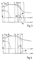
- Figures 2, 3, 4 and 5 show time-line plots explaining this.
- the lower portion of the graph relates to driver braking (DB).
- DB driver braking
- the driver must press with some minimum force before the brakes 31 become effective. In the figures, this minimum force coincides with the upper time axis.
- the vehicle 1 is initially travelling at a steady velocity (V) at an accelerator pedal setting (A).
- V steady velocity
- A accelerator pedal setting
- the driver sets the cruise controller 2 on at a higher target speed (TS), and releases his foot from the accelerator pedal 12.
- TS target speed
- the vehicle has reached the higher target speed TS, and remains at this speed until time t c .
- the target speed TS drops steadily. This could be because the driver is reducing the cruise speed manually with the cruise setting controls 36, or because the vehicle proximity radar unit 30 is indicating a decrease below a minimum acceptable separation with a vehicle in front.
- the vehicle speed starts to drop as the engine power demand is dropped to a minimum idle value.
- the vehicle speed V does not drop as quickly as the target speed TS, with the result that when the vehicle speed V is sufficiently above (e.g. 5 km/h above) the target speed T at time t d , the cruise controller 2 automatically demands braking (AB).
- AB braking
- the operation of the cruise controller is the same as Figure 2 until a time t g , shortly after time t d , at which the driver begins to press (DB) and hold the brake pedal 20 in order to slow the vehicle speed more rapidly than the automatic braking.
- the sustained pressure on the brake pedal 20 is insufficient to activate the brakes 31.
- the automatic braking AB begins to drop steadily in a progressive deactivation of cruise control braking.
- the driver braking starts to take effect only when the driver braking DB crosses the automatic braking AB at point indicated by reference numeral 50.
- the cruise controller 2 is then immediately deactivated at time t h .
- the vehicle continues to slow under driver braking DB until time t i , after which the vehicle coasts at a steadily dropping speed.
- Figure 4 shows a braking situation intermediate that of Figure 2 and 3. Again, the plot is similar to Figures 2 and 3 until a time t j after time t d at which point the driver touches DB and holds the brake pedal 2 but not heavily enough to activate the brakes 31. The automatic braking AB is then steadily reduced by the cruise controller 2 over a period of one second, until at time t k the cruise controller 2 is fully deactivated. Thereafter, the vehicle coasts slower.
- Figure 5 is again similar to the preceding plots up to time t d , after which during automatic braking AB by the cruise controller 2, the driver presses the accelerator pedal 12 at time t m . This immediately causes the cruise control 2 to become deactivated. If, however, the accelerator 12 had been pressed when the cruise control 2 was active but not automatically applying the brakes 31, the cruise control 2 would not have been deactivated.
- the invention therefore provides a vehicle speed control system with automatic cruise control braking, which responds under driver braking in a way which avoids a sudden and unexpected loss of braking effort.
Priority Applications (1)
| Application Number | Priority Date | Filing Date | Title |
|---|---|---|---|
| EP99307148A EP1083075A1 (de) | 1999-09-09 | 1999-09-09 | Abstandsgeregelter Tempomat mit aktivem Bremseingriff |
Applications Claiming Priority (1)
| Application Number | Priority Date | Filing Date | Title |
|---|---|---|---|
| EP99307148A EP1083075A1 (de) | 1999-09-09 | 1999-09-09 | Abstandsgeregelter Tempomat mit aktivem Bremseingriff |
Publications (1)
| Publication Number | Publication Date |
|---|---|
| EP1083075A1 true EP1083075A1 (de) | 2001-03-14 |
Family
ID=8241612
Family Applications (1)
| Application Number | Title | Priority Date | Filing Date |
|---|---|---|---|
| EP99307148A Withdrawn EP1083075A1 (de) | 1999-09-09 | 1999-09-09 | Abstandsgeregelter Tempomat mit aktivem Bremseingriff |
Country Status (1)
| Country | Link |
|---|---|
| EP (1) | EP1083075A1 (de) |
Cited By (9)
| Publication number | Priority date | Publication date | Assignee | Title |
|---|---|---|---|---|
| EP1177958A3 (de) * | 2000-08-04 | 2003-02-12 | Toyota Jidosha Kabushiki Kaisha | Vorrichtung und Verfahren zur Bremssteuerung von Kraftfahrzeugen |
| EP1298625A1 (de) * | 2001-09-28 | 2003-04-02 | Renault s.a.s. | Verfahren und Gerät zur Regelung des Abstandes zwischen zwei Fahrzeugen |
| EP1593567A1 (de) * | 2004-05-07 | 2005-11-09 | Delphi Technologies, Inc. | Funktion zur Fahrunterstützung während des Verfolgens einer Reihe von Fahrzeugen |
| EP1336526A3 (de) * | 2002-02-18 | 2006-11-08 | Hitachi, Ltd. | Verfahren, System und Regler für abstandsbezogene Fahrgeschwindigkeitsregelung in einem Fahrzeug |
| WO2007113132A1 (de) * | 2006-04-03 | 2007-10-11 | Robert Bosch Gmbh | Anpassung eines bremsassistenten bei einer fahrerbremsung |
| DE102010019498A1 (de) | 2010-05-06 | 2011-11-10 | Gm Global Technology Operations Llc (N.D.Ges.D. Staates Delaware) | Verfahren zum automatischen Abbremsen eines Kraftfahrzeugs und Kraftfahrzeug mit einer Abstandsregelvorrichtung |
| US8224551B2 (en) | 2009-03-24 | 2012-07-17 | Bendix Commercial Vehicle Systems Llc | ACC extended mode operation |
| DE102008014315B4 (de) * | 2007-03-19 | 2019-11-28 | GM Global Technology Operations LLC (n. d. Ges. d. Staates Delaware) | Ausserkraftsetzen eines automatischen Bremsens in einem Kollisionsabschwächungs- und/oder -vermeidungssystem |
| CN112389429A (zh) * | 2020-10-23 | 2021-02-23 | 上汽通用五菱汽车股份有限公司 | 自适应巡航控制方法、自适应巡航系统、车辆及存储介质 |
Citations (8)
| Publication number | Priority date | Publication date | Assignee | Title |
|---|---|---|---|---|
| DE2334904A1 (de) * | 1973-07-10 | 1975-01-30 | Walter Gerhard | Sicherheitsbremse |
| DE2900461A1 (de) * | 1979-01-08 | 1980-07-24 | Bosch Gmbh Robert | Einrichtung zur regelung der fahrgeschwindigkeit eines fahrzeugs |
| US4641136A (en) * | 1985-04-18 | 1987-02-03 | Thaddeus Kowalczyk | Security eyes for prevention of car accidents |
| EP0484995A2 (de) * | 1990-11-05 | 1992-05-13 | General Motors Corporation | Verfahren zur Steuerung der Geschwindigkeit eines Fahrzeugs |
| EP0819591A1 (de) * | 1996-07-20 | 1998-01-21 | Daimler-Benz Aktiengesellschaft | Verfahren zur Durchführung eines automatischen Bremsvorgangs |
| EP0867349A2 (de) * | 1997-03-27 | 1998-09-30 | Bayerische Motoren Werke Aktiengesellschaft, Patentabteilung AJ-3 | Bremsregelungsanlage für Kraftfahrzeuge mit einer ein- und ausschaltbaren elektronischen Geschwindigkeitsregeleinheit |
| EP0867325A2 (de) * | 1997-03-27 | 1998-09-30 | Bayerische Motoren Werke Aktiengesellschaft, Patentabteilung AJ-3 | Bremsregelungsanlage für Kraftfahrzeuge mit einer ein- und ausschaltbaren elektronischen Geschwindigkeitsregeleinheit |
| DE19834409A1 (de) * | 1997-08-04 | 1999-02-11 | Mitsubishi Motors Corp | Fahrtreglersystem für ein Kraftfahrzeug |
-
1999
- 1999-09-09 EP EP99307148A patent/EP1083075A1/de not_active Withdrawn
Patent Citations (8)
| Publication number | Priority date | Publication date | Assignee | Title |
|---|---|---|---|---|
| DE2334904A1 (de) * | 1973-07-10 | 1975-01-30 | Walter Gerhard | Sicherheitsbremse |
| DE2900461A1 (de) * | 1979-01-08 | 1980-07-24 | Bosch Gmbh Robert | Einrichtung zur regelung der fahrgeschwindigkeit eines fahrzeugs |
| US4641136A (en) * | 1985-04-18 | 1987-02-03 | Thaddeus Kowalczyk | Security eyes for prevention of car accidents |
| EP0484995A2 (de) * | 1990-11-05 | 1992-05-13 | General Motors Corporation | Verfahren zur Steuerung der Geschwindigkeit eines Fahrzeugs |
| EP0819591A1 (de) * | 1996-07-20 | 1998-01-21 | Daimler-Benz Aktiengesellschaft | Verfahren zur Durchführung eines automatischen Bremsvorgangs |
| EP0867349A2 (de) * | 1997-03-27 | 1998-09-30 | Bayerische Motoren Werke Aktiengesellschaft, Patentabteilung AJ-3 | Bremsregelungsanlage für Kraftfahrzeuge mit einer ein- und ausschaltbaren elektronischen Geschwindigkeitsregeleinheit |
| EP0867325A2 (de) * | 1997-03-27 | 1998-09-30 | Bayerische Motoren Werke Aktiengesellschaft, Patentabteilung AJ-3 | Bremsregelungsanlage für Kraftfahrzeuge mit einer ein- und ausschaltbaren elektronischen Geschwindigkeitsregeleinheit |
| DE19834409A1 (de) * | 1997-08-04 | 1999-02-11 | Mitsubishi Motors Corp | Fahrtreglersystem für ein Kraftfahrzeug |
Cited By (11)
| Publication number | Priority date | Publication date | Assignee | Title |
|---|---|---|---|---|
| EP1177958A3 (de) * | 2000-08-04 | 2003-02-12 | Toyota Jidosha Kabushiki Kaisha | Vorrichtung und Verfahren zur Bremssteuerung von Kraftfahrzeugen |
| EP1298625A1 (de) * | 2001-09-28 | 2003-04-02 | Renault s.a.s. | Verfahren und Gerät zur Regelung des Abstandes zwischen zwei Fahrzeugen |
| FR2830359A1 (fr) * | 2001-09-28 | 2003-04-04 | Renault | Procede et dispositif de regulation de distance entre deux vehicules automobiles |
| EP1336526A3 (de) * | 2002-02-18 | 2006-11-08 | Hitachi, Ltd. | Verfahren, System und Regler für abstandsbezogene Fahrgeschwindigkeitsregelung in einem Fahrzeug |
| EP1593567A1 (de) * | 2004-05-07 | 2005-11-09 | Delphi Technologies, Inc. | Funktion zur Fahrunterstützung während des Verfolgens einer Reihe von Fahrzeugen |
| US7917273B2 (en) | 2004-05-07 | 2011-03-29 | Belen Alvarez | Driving assistance function on following a queue of vehicles |
| WO2007113132A1 (de) * | 2006-04-03 | 2007-10-11 | Robert Bosch Gmbh | Anpassung eines bremsassistenten bei einer fahrerbremsung |
| DE102008014315B4 (de) * | 2007-03-19 | 2019-11-28 | GM Global Technology Operations LLC (n. d. Ges. d. Staates Delaware) | Ausserkraftsetzen eines automatischen Bremsens in einem Kollisionsabschwächungs- und/oder -vermeidungssystem |
| US8224551B2 (en) | 2009-03-24 | 2012-07-17 | Bendix Commercial Vehicle Systems Llc | ACC extended mode operation |
| DE102010019498A1 (de) | 2010-05-06 | 2011-11-10 | Gm Global Technology Operations Llc (N.D.Ges.D. Staates Delaware) | Verfahren zum automatischen Abbremsen eines Kraftfahrzeugs und Kraftfahrzeug mit einer Abstandsregelvorrichtung |
| CN112389429A (zh) * | 2020-10-23 | 2021-02-23 | 上汽通用五菱汽车股份有限公司 | 自适应巡航控制方法、自适应巡航系统、车辆及存储介质 |
Similar Documents
| Publication | Publication Date | Title |
|---|---|---|
| US5713428A (en) | Apparatus for regulating the speed of a motor vehicle | |
| US6302823B1 (en) | Method and device for maneuvering motor vehicles | |
| US4629043A (en) | Electric parking brake system for a vehicle | |
| US9248810B2 (en) | Accelerator braking module | |
| US5924508A (en) | Process for carrying out an automatic braking operation | |
| JP6596151B2 (ja) | 車速制御方法及び車速制御システム | |
| US7762633B2 (en) | Brake control system | |
| US6233514B1 (en) | Method for controlling the downhill speed of an off-the-road vehicle | |
| EP1702786A1 (de) | Fahrgeschwindigkeitsregler mit Fahrzeugstillstandsfunktion | |
| US7762926B2 (en) | Hill hold method and system | |
| GB2319636A (en) | Method of speed control for a vehicle on a gradient | |
| EP0992412B1 (de) | Kraftfahrzeugbremsregelung | |
| US6628197B1 (en) | Device for brake light control | |
| EP1083075A1 (de) | Abstandsgeregelter Tempomat mit aktivem Bremseingriff | |
| US7401873B2 (en) | Method for preventing a stationary vehicle from unintentionally rolling | |
| EP2060467B1 (de) | Dynamisch einstellbare Langsamgang/Bremsen-Überdeckung zur Fahrzeuggetriebesteuerung | |
| US6193021B1 (en) | Method and device for adjusting or altering the play between brake linings and friction surfaces of motor vehicle brakes | |
| US6742850B1 (en) | Method for adjusting a brake system of a vehicle | |
| US9434274B2 (en) | Speed control system for motor vehicles | |
| EP0839684A1 (de) | System zur Steuerung des Parkens und des Startens am Berg eines Kraftfahrzeuges | |
| WO2013000042A1 (en) | Improved accelerator pedal with braking action | |
| JP3744073B2 (ja) | 緊急ブレーキアシストシステム | |
| AU2018282491B1 (en) | Improved Accelerator Pedal with Braking Action | |
| US6532411B2 (en) | Brake booster control device and method of controlling the same | |
| CN113874237A (zh) | 用于车辆的速度调整系统和用于调整行驶速度的方法 |
Legal Events
| Date | Code | Title | Description |
|---|---|---|---|
| PUAI | Public reference made under article 153(3) epc to a published international application that has entered the european phase |
Free format text: ORIGINAL CODE: 0009012 |
|
| AK | Designated contracting states |
Kind code of ref document: A1 Designated state(s): DE FR GB |
|
| AX | Request for extension of the european patent |
Free format text: AL;LT;LV;MK;RO;SI |
|
| 17P | Request for examination filed |
Effective date: 20010730 |
|
| AKX | Designation fees paid |
Free format text: DE FR GB |
|
| 17Q | First examination report despatched |
Effective date: 20040317 |
|
| STAA | Information on the status of an ep patent application or granted ep patent |
Free format text: STATUS: THE APPLICATION IS DEEMED TO BE WITHDRAWN |
|
| 18D | Application deemed to be withdrawn |
Effective date: 20050915 |