EP1082231B1 - Method and device for controlling a prime mover - Google Patents
Method and device for controlling a prime mover Download PDFInfo
- Publication number
- EP1082231B1 EP1082231B1 EP99932618A EP99932618A EP1082231B1 EP 1082231 B1 EP1082231 B1 EP 1082231B1 EP 99932618 A EP99932618 A EP 99932618A EP 99932618 A EP99932618 A EP 99932618A EP 1082231 B1 EP1082231 B1 EP 1082231B1
- Authority
- EP
- European Patent Office
- Prior art keywords
- torque
- tqi
- internal combustion
- combustion engine
- value
- Prior art date
- Legal status (The legal status is an assumption and is not a legal conclusion. Google has not performed a legal analysis and makes no representation as to the accuracy of the status listed.)
- Expired - Lifetime
Links
Images


Classifications
-
- B—PERFORMING OPERATIONS; TRANSPORTING
- B60—VEHICLES IN GENERAL
- B60K—ARRANGEMENT OR MOUNTING OF PROPULSION UNITS OR OF TRANSMISSIONS IN VEHICLES; ARRANGEMENT OR MOUNTING OF PLURAL DIVERSE PRIME-MOVERS IN VEHICLES; AUXILIARY DRIVES FOR VEHICLES; INSTRUMENTATION OR DASHBOARDS FOR VEHICLES; ARRANGEMENTS IN CONNECTION WITH COOLING, AIR INTAKE, GAS EXHAUST OR FUEL SUPPLY OF PROPULSION UNITS IN VEHICLES
- B60K6/00—Arrangement or mounting of plural diverse prime-movers for mutual or common propulsion, e.g. hybrid propulsion systems comprising electric motors and internal combustion engines ; Control systems therefor, i.e. systems controlling two or more prime movers, or controlling one of these prime movers and any of the transmission, drive or drive units Informative references: mechanical gearings with secondary electric drive F16H3/72; arrangements for handling mechanical energy structurally associated with the dynamo-electric machine H02K7/00; machines comprising structurally interrelated motor and generator parts H02K51/00; dynamo-electric machines not otherwise provided for in H02K see H02K99/00
- B60K6/20—Arrangement or mounting of plural diverse prime-movers for mutual or common propulsion, e.g. hybrid propulsion systems comprising electric motors and internal combustion engines ; Control systems therefor, i.e. systems controlling two or more prime movers, or controlling one of these prime movers and any of the transmission, drive or drive units Informative references: mechanical gearings with secondary electric drive F16H3/72; arrangements for handling mechanical energy structurally associated with the dynamo-electric machine H02K7/00; machines comprising structurally interrelated motor and generator parts H02K51/00; dynamo-electric machines not otherwise provided for in H02K see H02K99/00 the prime-movers consisting of electric motors and internal combustion engines, e.g. HEVs
- B60K6/42—Arrangement or mounting of plural diverse prime-movers for mutual or common propulsion, e.g. hybrid propulsion systems comprising electric motors and internal combustion engines ; Control systems therefor, i.e. systems controlling two or more prime movers, or controlling one of these prime movers and any of the transmission, drive or drive units Informative references: mechanical gearings with secondary electric drive F16H3/72; arrangements for handling mechanical energy structurally associated with the dynamo-electric machine H02K7/00; machines comprising structurally interrelated motor and generator parts H02K51/00; dynamo-electric machines not otherwise provided for in H02K see H02K99/00 the prime-movers consisting of electric motors and internal combustion engines, e.g. HEVs characterised by the architecture of the hybrid electric vehicle
- B60K6/48—Parallel type
- B60K6/485—Motor-assist type
-
- B—PERFORMING OPERATIONS; TRANSPORTING
- B60—VEHICLES IN GENERAL
- B60W—CONJOINT CONTROL OF VEHICLE SUB-UNITS OF DIFFERENT TYPE OR DIFFERENT FUNCTION; CONTROL SYSTEMS SPECIALLY ADAPTED FOR HYBRID VEHICLES; ROAD VEHICLE DRIVE CONTROL SYSTEMS FOR PURPOSES NOT RELATED TO THE CONTROL OF A PARTICULAR SUB-UNIT
- B60W20/00—Control systems specially adapted for hybrid vehicles
- B60W20/40—Controlling the engagement or disengagement of prime movers, e.g. for transition between prime movers
-
- B—PERFORMING OPERATIONS; TRANSPORTING
- B60—VEHICLES IN GENERAL
- B60W—CONJOINT CONTROL OF VEHICLE SUB-UNITS OF DIFFERENT TYPE OR DIFFERENT FUNCTION; CONTROL SYSTEMS SPECIALLY ADAPTED FOR HYBRID VEHICLES; ROAD VEHICLE DRIVE CONTROL SYSTEMS FOR PURPOSES NOT RELATED TO THE CONTROL OF A PARTICULAR SUB-UNIT
- B60W10/00—Conjoint control of vehicle sub-units of different type or different function
- B60W10/04—Conjoint control of vehicle sub-units of different type or different function including control of propulsion units
- B60W10/06—Conjoint control of vehicle sub-units of different type or different function including control of propulsion units including control of combustion engines
-
- B—PERFORMING OPERATIONS; TRANSPORTING
- B60—VEHICLES IN GENERAL
- B60W—CONJOINT CONTROL OF VEHICLE SUB-UNITS OF DIFFERENT TYPE OR DIFFERENT FUNCTION; CONTROL SYSTEMS SPECIALLY ADAPTED FOR HYBRID VEHICLES; ROAD VEHICLE DRIVE CONTROL SYSTEMS FOR PURPOSES NOT RELATED TO THE CONTROL OF A PARTICULAR SUB-UNIT
- B60W10/00—Conjoint control of vehicle sub-units of different type or different function
- B60W10/04—Conjoint control of vehicle sub-units of different type or different function including control of propulsion units
- B60W10/08—Conjoint control of vehicle sub-units of different type or different function including control of propulsion units including control of electric propulsion units, e.g. motors or generators
-
- B—PERFORMING OPERATIONS; TRANSPORTING
- B60—VEHICLES IN GENERAL
- B60W—CONJOINT CONTROL OF VEHICLE SUB-UNITS OF DIFFERENT TYPE OR DIFFERENT FUNCTION; CONTROL SYSTEMS SPECIALLY ADAPTED FOR HYBRID VEHICLES; ROAD VEHICLE DRIVE CONTROL SYSTEMS FOR PURPOSES NOT RELATED TO THE CONTROL OF A PARTICULAR SUB-UNIT
- B60W20/00—Control systems specially adapted for hybrid vehicles
-
- F—MECHANICAL ENGINEERING; LIGHTING; HEATING; WEAPONS; BLASTING
- F02—COMBUSTION ENGINES; HOT-GAS OR COMBUSTION-PRODUCT ENGINE PLANTS
- F02D—CONTROLLING COMBUSTION ENGINES
- F02D41/00—Electrical control of supply of combustible mixture or its constituents
- F02D41/24—Electrical control of supply of combustible mixture or its constituents characterised by the use of digital means
- F02D41/26—Electrical control of supply of combustible mixture or its constituents characterised by the use of digital means using computer, e.g. microprocessor
- F02D41/28—Interface circuits
-
- B—PERFORMING OPERATIONS; TRANSPORTING
- B60—VEHICLES IN GENERAL
- B60L—PROPULSION OF ELECTRICALLY-PROPELLED VEHICLES; SUPPLYING ELECTRIC POWER FOR AUXILIARY EQUIPMENT OF ELECTRICALLY-PROPELLED VEHICLES; ELECTRODYNAMIC BRAKE SYSTEMS FOR VEHICLES IN GENERAL; MAGNETIC SUSPENSION OR LEVITATION FOR VEHICLES; MONITORING OPERATING VARIABLES OF ELECTRICALLY-PROPELLED VEHICLES; ELECTRIC SAFETY DEVICES FOR ELECTRICALLY-PROPELLED VEHICLES
- B60L2240/00—Control parameters of input or output; Target parameters
- B60L2240/40—Drive Train control parameters
- B60L2240/42—Drive Train control parameters related to electric machines
- B60L2240/423—Torque
-
- B—PERFORMING OPERATIONS; TRANSPORTING
- B60—VEHICLES IN GENERAL
- B60W—CONJOINT CONTROL OF VEHICLE SUB-UNITS OF DIFFERENT TYPE OR DIFFERENT FUNCTION; CONTROL SYSTEMS SPECIALLY ADAPTED FOR HYBRID VEHICLES; ROAD VEHICLE DRIVE CONTROL SYSTEMS FOR PURPOSES NOT RELATED TO THE CONTROL OF A PARTICULAR SUB-UNIT
- B60W50/00—Details of control systems for road vehicle drive control not related to the control of a particular sub-unit, e.g. process diagnostic or vehicle driver interfaces
- B60W2050/0001—Details of the control system
- B60W2050/0019—Control system elements or transfer functions
- B60W2050/0042—Transfer function lag; delays
-
- B—PERFORMING OPERATIONS; TRANSPORTING
- B60—VEHICLES IN GENERAL
- B60W—CONJOINT CONTROL OF VEHICLE SUB-UNITS OF DIFFERENT TYPE OR DIFFERENT FUNCTION; CONTROL SYSTEMS SPECIALLY ADAPTED FOR HYBRID VEHICLES; ROAD VEHICLE DRIVE CONTROL SYSTEMS FOR PURPOSES NOT RELATED TO THE CONTROL OF A PARTICULAR SUB-UNIT
- B60W50/00—Details of control systems for road vehicle drive control not related to the control of a particular sub-unit, e.g. process diagnostic or vehicle driver interfaces
- B60W2050/0001—Details of the control system
- B60W2050/0043—Signal treatments, identification of variables or parameters, parameter estimation or state estimation
- B60W2050/0052—Filtering, filters
-
- B—PERFORMING OPERATIONS; TRANSPORTING
- B60—VEHICLES IN GENERAL
- B60W—CONJOINT CONTROL OF VEHICLE SUB-UNITS OF DIFFERENT TYPE OR DIFFERENT FUNCTION; CONTROL SYSTEMS SPECIALLY ADAPTED FOR HYBRID VEHICLES; ROAD VEHICLE DRIVE CONTROL SYSTEMS FOR PURPOSES NOT RELATED TO THE CONTROL OF A PARTICULAR SUB-UNIT
- B60W2510/00—Input parameters relating to a particular sub-units
- B60W2510/06—Combustion engines, Gas turbines
- B60W2510/0614—Position of fuel or air injector
- B60W2510/0628—Inlet air flow rate
-
- B—PERFORMING OPERATIONS; TRANSPORTING
- B60—VEHICLES IN GENERAL
- B60W—CONJOINT CONTROL OF VEHICLE SUB-UNITS OF DIFFERENT TYPE OR DIFFERENT FUNCTION; CONTROL SYSTEMS SPECIALLY ADAPTED FOR HYBRID VEHICLES; ROAD VEHICLE DRIVE CONTROL SYSTEMS FOR PURPOSES NOT RELATED TO THE CONTROL OF A PARTICULAR SUB-UNIT
- B60W2710/00—Output or target parameters relating to a particular sub-units
- B60W2710/06—Combustion engines, Gas turbines
- B60W2710/0616—Position of fuel or air injector
-
- B—PERFORMING OPERATIONS; TRANSPORTING
- B60—VEHICLES IN GENERAL
- B60W—CONJOINT CONTROL OF VEHICLE SUB-UNITS OF DIFFERENT TYPE OR DIFFERENT FUNCTION; CONTROL SYSTEMS SPECIALLY ADAPTED FOR HYBRID VEHICLES; ROAD VEHICLE DRIVE CONTROL SYSTEMS FOR PURPOSES NOT RELATED TO THE CONTROL OF A PARTICULAR SUB-UNIT
- B60W2710/00—Output or target parameters relating to a particular sub-units
- B60W2710/06—Combustion engines, Gas turbines
- B60W2710/0666—Engine torque
-
- B—PERFORMING OPERATIONS; TRANSPORTING
- B60—VEHICLES IN GENERAL
- B60W—CONJOINT CONTROL OF VEHICLE SUB-UNITS OF DIFFERENT TYPE OR DIFFERENT FUNCTION; CONTROL SYSTEMS SPECIALLY ADAPTED FOR HYBRID VEHICLES; ROAD VEHICLE DRIVE CONTROL SYSTEMS FOR PURPOSES NOT RELATED TO THE CONTROL OF A PARTICULAR SUB-UNIT
- B60W2710/00—Output or target parameters relating to a particular sub-units
- B60W2710/08—Electric propulsion units
- B60W2710/083—Torque
-
- F—MECHANICAL ENGINEERING; LIGHTING; HEATING; WEAPONS; BLASTING
- F02—COMBUSTION ENGINES; HOT-GAS OR COMBUSTION-PRODUCT ENGINE PLANTS
- F02D—CONTROLLING COMBUSTION ENGINES
- F02D2200/00—Input parameters for engine control
- F02D2200/02—Input parameters for engine control the parameters being related to the engine
- F02D2200/10—Parameters related to the engine output, e.g. engine torque or engine speed
- F02D2200/1006—Engine torque losses, e.g. friction or pumping losses or losses caused by external loads of accessories
-
- Y—GENERAL TAGGING OF NEW TECHNOLOGICAL DEVELOPMENTS; GENERAL TAGGING OF CROSS-SECTIONAL TECHNOLOGIES SPANNING OVER SEVERAL SECTIONS OF THE IPC; TECHNICAL SUBJECTS COVERED BY FORMER USPC CROSS-REFERENCE ART COLLECTIONS [XRACs] AND DIGESTS
- Y02—TECHNOLOGIES OR APPLICATIONS FOR MITIGATION OR ADAPTATION AGAINST CLIMATE CHANGE
- Y02T—CLIMATE CHANGE MITIGATION TECHNOLOGIES RELATED TO TRANSPORTATION
- Y02T10/00—Road transport of goods or passengers
- Y02T10/10—Internal combustion engine [ICE] based vehicles
- Y02T10/40—Engine management systems
-
- Y—GENERAL TAGGING OF NEW TECHNOLOGICAL DEVELOPMENTS; GENERAL TAGGING OF CROSS-SECTIONAL TECHNOLOGIES SPANNING OVER SEVERAL SECTIONS OF THE IPC; TECHNICAL SUBJECTS COVERED BY FORMER USPC CROSS-REFERENCE ART COLLECTIONS [XRACs] AND DIGESTS
- Y02—TECHNOLOGIES OR APPLICATIONS FOR MITIGATION OR ADAPTATION AGAINST CLIMATE CHANGE
- Y02T—CLIMATE CHANGE MITIGATION TECHNOLOGIES RELATED TO TRANSPORTATION
- Y02T10/00—Road transport of goods or passengers
- Y02T10/60—Other road transportation technologies with climate change mitigation effect
- Y02T10/62—Hybrid vehicles
-
- Y—GENERAL TAGGING OF NEW TECHNOLOGICAL DEVELOPMENTS; GENERAL TAGGING OF CROSS-SECTIONAL TECHNOLOGIES SPANNING OVER SEVERAL SECTIONS OF THE IPC; TECHNICAL SUBJECTS COVERED BY FORMER USPC CROSS-REFERENCE ART COLLECTIONS [XRACs] AND DIGESTS
- Y02—TECHNOLOGIES OR APPLICATIONS FOR MITIGATION OR ADAPTATION AGAINST CLIMATE CHANGE
- Y02T—CLIMATE CHANGE MITIGATION TECHNOLOGIES RELATED TO TRANSPORTATION
- Y02T10/00—Road transport of goods or passengers
- Y02T10/60—Other road transportation technologies with climate change mitigation effect
- Y02T10/64—Electric machine technologies in electromobility
Definitions
- the invention relates to a method according to the preamble of claim 1 and a device according to the preamble of claim 9.
- a method for controlling an internal combustion engine is off known from DE 196 12 455 A1.
- a setpoint of a torque becomes dependent on the accelerator pedal position of an accelerator pedal, the Speed and other operating parameters such as air mass flow, the coolant temperature and the oil temperature.
- Dependent a control signal for a Throttle valve actuator determined. That about the air mass flow
- the torque to be set is determined taking into account of the target torque and lead values of Torque by functions to control the internal combustion engine, such as traction control, speed limitation, a speed limit and a catalyst heating function, be requested.
- There is also a setpoint of the torque that can be set quickly from the target torque and torque requirements of the others Functions for controlling the internal combustion engine.
- An actuating signal for a spark plug depends on the setpoint of the Torque.
- crankshaft segment By changing the ignition angle can be within of a crankshaft segment that is actually in a cylinder the torque generated by the internal combustion engine is changed become.
- the duration of a crankshaft segment is, for example by the time interval between the ignitions of two defined in the firing order of adjacent cylinders.
- the setpoint of the Torque to be set via the air mass flow only be adjusted slowly. Does that actually tell of the Torque to be generated by the internal combustion engine is highly dynamic on, the lead values must be chosen large in order to Set torque with high quality. However, this has high Exhaust emissions from the internal combustion engine and a high Result in fuel consumption.
- JP-A-09084211 is another method for controlling one An engine comprising an internal combustion engine.
- a setpoint of a torque is dependent of a size and representing the driver's request
- Operating variables of the internal combustion engine determined.
- control signals for actuators of the internal combustion engine are determined dependent from the setpoint of the torque.
- An estimate of one maximum torque is determined using the actuators the internal combustion engine within a predetermined Time is adjustable. The determination of this estimate is done by adding a torque increase value per predetermined period of time at which in a previous calculation cycle set old torque value.
- On Control signal for a motor generator is then dependent on the target value and the estimated value of the maximum torque.
- the object of the invention is a device and a To provide methods of controlling an engine which is comfortable and low in emissions Operation of the internal combustion engine with high efficiency the engine is guaranteed and precise.
- the object is achieved through the features of the independent claims solved.
- the invention is characterized in that that a control signal for a motor generator that is on the drive shaft the internal combustion engine is arranged, depending is determined from the nominal value of the torque.
- the engine generator has a response time that is significantly lower than the length of time until a jump in the setpoint torque is set via the air mass flow. So they can Reserve values for the one to be set via the air mass flow Torque can be selected lower without sacrificing comfort to have to put up with.
- the invention is further characterized in that the Control signal for that designed as a spark plug or injection valve Actuator depends on a setpoint of the torque and the estimate of the actual motor generator Torque. This is an extremely precise adjustment of the Torque setpoint enabled.
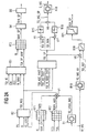
- An engine ( Figure 1) includes an internal combustion engine.
- the internal combustion engine has an intake tract 1 with a Throttle valve 10 and an engine block 2, which is a cylinder 20 and a crankshaft 23.
- a piston 21 and one Connecting rod 22 are assigned to cylinder 20.
- the connecting rod 22 is connected to the piston 21 and the crankshaft 23.
- a cylinder head 3 is provided in which a valve train is arranged is with at least one inlet valve 30, an outlet valve 31 and one each assigned to the inlet valve 30 Valve drive 32a and one associated with the exhaust valve 31 Valve actuator 32b.
- An injection valve 11 is introduced into the intake tract 1, which is arranged so that the fuel in the intake tract 1 is measured.
- the injection valve 11 can alternatively also be introduced into the cylinder head 3 and arranged there be that the fuel directly into the interior of the Cylinder 20 is metered.
- a spark plug 34 is in a Recess of the cylinder head 3 introduced.
- the internal combustion engine is shown in Figure 1 with a cylinder. However, it can also comprise several cylinders.
- An exhaust tract 4 is assigned to the internal combustion engine.
- Motor-generator 5 is provided, the rotor of which is non-positive is connected to the crankshaft 23.
- the engine generator is preferably designed as an asynchronous machine. However, he can also as a synchronous machine or as a DC motor be trained.
- the crankshaft 23 is the in engine operation Output shaft of the motor generator and in generator operation the drive shaft of the motor generator.
- the motor generator 5 replaces the starter and the usual generator one Internal combustion engine. The engine is therefore essential compact.
- the crankshaft 23 is not connected to a clutch 6 shown transmission can be coupled. If the transmission as an automatic transmission is formed, then the clutch 6 is for example preferably as a lockup clutch a hydrodynamic converter.
- a control device 7 for the engine is provided, the sensors are assigned to the various measured variables record and determine the measured value of the measured variable.
- the Control device 7 determines depending on at least one Operating variable one or more control signals that an actuator Taxes.
- the sensors are a pedal position sensor 81, which is a pedal position PV of the accelerator pedal 8 detects a throttle position transmitter 12, which detects an opening degree of the throttle valve, an air mass meter 13 which detects an air mass flow and / or an intake manifold pressure sensor 14, which is an intake manifold pressure detected in the intake tract 1, a first temperature sensor 15 which detects an intake air temperature, a speed sensor 24, which detects a rotational speed N of the crankshaft 23, and a second and third temperature sensor 26, 27, which is an oil temperature TOIL or a coolant temperature TCO to capture. Furthermore, a measuring unit 51 is provided which characteristic operating variable of the motor generator 5 detected. The characteristic operating size of the motor generator 5 can be, for example, a current or a voltage or be an achievement.
- the control device 7 can any subset of the sensors mentioned can be assigned, additional sensors can also be assigned here his.
- Operating variables include measured variables and those derived from them Sizes that are related to or from a map Observers are determined, the estimates of the farm sizes calculated.
- the actuators each include an actuator and a Actuator.
- the actuator is an electric motor drive, an electromagnetic drive, a mechanical one or another drive known to the person skilled in the art.
- the actuators are as a throttle valve 10, as an injection valve 11, as a spark plug 34 or as another to the specialist in internal combustion engines known actuators trained.
- On the Actuators are assigned below with the respectively Actuator referred.
- the control device is preferably an electronic engine control educated. However, it can also have several control units include the electrically connected together are, e.g. with a bus system.
- a map KF1 is provided, from which a first contribution TQFR to a loss torque TQ_LOSS depending on the Speed N, and the estimated value MAF_CYL of the air mass flow is determined in the cylinder 20.
- the first contribution to the TQFR Loss torque TQ_LOSS takes pump losses into account Internal combustion engine and losses caused by friction at given Reference values of the coolant temperature TCO and the Oil temperature TOIL occur.
- a second contribution TQFR_ADD to the loss torque TQ_LOSS is determined from a map KF2 depending on the oil temperature TOIL and / or the coolant temperature TCO. Furthermore, a third contribution TQ_LOSS_MG to the loss torque is determined as a function of the measurement signal M_MG that is generated by the measurement unit 51. The third contribution TQ_LOSS_MG to the loss torque TQ_LOSS is determined in a block B1 using a dynamic model of the losses of the motor generator.
- the dynamic model of the losses of the motor generator 5 preferably comprises a characteristic curve in which the characteristic values of the third contribution TQ_LOSS_MG are stored as a function of a detected current through the motor generator 5.
- the characteristic values are corrected with a correction factor which depends on the temperature of the motor generator, this correction factor preferably being subjected to PD 1 filtering.
- the temperature of the motor generator is either determined directly or determined from a map depending on the power supplied or removed by the motor generator.
- the intake temperature is also taken into account when correcting the third contribution TQ_LOSS_MG to the loss torque TQ_LOSS.
- the contributions TQFR, TQFR_ADD, TQ_LOSS_MG are added in a node V1. Their sum then forms the loss torque TQ_LOSS.
- block B2 there is an available torque range depending on the loss torque TQ_LOSS and the speed N determined. From the accelerator pedal position PV and the speed N is determined, what proportion of the available adjustable torque range requested by the driver becomes. From the requested portion of the torque and the The torque that can be made available is then a driver's request corresponding value TQI_REQ of the torque is determined. Filtering of the driver's request is also preferred corresponding value TQI_REQ of the torque is provided, to ensure that no load jumps can occur, which lead to an uncomfortable jerking of the vehicle, in which the engine is arranged.
- a setpoint TQI_SP_MAF of the Determined air mass flow torque there in addition to the value TQI_REQ of the torque, lead values considered. For example, a lead value TQI_IS specified by an idle controller, a lead value TQI_CH of a function for heating a catalytic converter specified, a lead value TQI_ASC from an anti-slip control specified, a lead value TQI_N_MAX of a function for speed limitation, or a Lead value TQI_MSR from a motor drag torque control specified.
- the setpoint TQI_SP_MAF of the air mass flow Torque to be set can thus be greater or be less than the value TQI_REQ of the torque corresponding to the Driver request corresponds.
- the setpoint TQI_SP_MAF of the is via a map KF3 the air mass flow to be set depending on a nominal value MAF_SP of the air mass flow is assigned to the speed N.
- the values of the map KF3 are from measurements on one Engine test bench with a reference air ratio LAM_REF and at a reference ignition angle IGA_REF derived or by a simulation calculation is determined.
- a control signal is generated in a block B5 determined to control the throttle valve 10, preferably from a position controller of the throttle valve 10.
- the setpoint TQI_SP_MAF to be set via the air mass flow Torque anticipates this under taking into account the dynamics of the intake tract Torque.
- a setpoint TQI_SP of the torque determined to set within a predetermined period of time is.
- the predetermined time period preferably corresponds the length of time determined by a crankshaft segment is.
- a crankshaft segment is determined by the angle between two top dead centers of two neighboring in the firing order Cylinder or even by the ignition interval of two in the firing order of neighboring cylinders.
- the setpoint TQI_SP of the Torque must therefore be very fast, e.g. within a Working cycle of the internal combustion engine to be adjustable.
- the setpoint TQI_SP of the torque depending on the value TQI_REQ corresponding to the driver's request of the torque and torque requirements TQI_ASC_FAST, TQI_GS_FAST, TQI_N_MAX_FAST an anti-slip control, one Transmission control and a function to limit the speed N calculated.
- other torque requirements can also be met be taken into account.
- a map KF4 is provided, from which depends from the estimated value MAF_CYL and the speed N a reference value TQI_REF of the torque is determined.
- the values of Kennfelds KF4 are from measurements on an engine test bench a reference air ratio LAM_REF and at a reference ignition angle IGA_REF derived or by a simulation calculation determined.
- the reference value TQI_REF of the torque is therefore always the torque that the corresponding Speed and the corresponding air mass flow in the Cylinder can theoretically be realized at maximum if at the same time the efficiency EFF_IGA related to the ignition angle and the efficiency EFF_LAM based on the air ratio are maximum.
- the reference ignition angle IGA_REF is shown in a map KF5 depending on the speed, the estimated value MAF_CYL of the air mass flow in the cylinder 20 and the coolant temperature TCO determined.
- the efficiency EFF_IGA of the ignition angle is standardized to the Efficiency of the ignition angle at the reference ignition angle IGA_REF.
- the reference air ratio LAM_REF is dependent on a map KF7 of the speed N and the estimated value MAF_CYL des Air mass flow in the cylinder 20 is determined.
- a pareto optimal The basic air ratio LAM_BAS is converted from a map KF8 depending on the speed N and an estimate MAF_CYL des Air mass flow in the cylinder 20 is determined.
- In a tie point V3 becomes the difference in the basic air ratio LAM_BAS and the reference air ratio LAM_REF formed and then the efficiency EFF_LAM of the air ratio is standardized in block B9 determined on the efficiency at the reference air ratio LAM_REF.
- the estimated value TQI_BAS is the maximum Torque from the product of the reference value TQI_REF des Torque of the efficiency EFF_IGA of the ignition angle and of the EFF_LAM efficiency of the air ratio.
- the Estimated value TQI_BAS of the maximum torque is therefore the highest value of the torque actually at a given MAF_CYL estimate of the air mass flow into the cylinder 20, the speed N and the coolant temperature through the Internal combustion engine can be applied.
- the underlying TQI_BAS of the torque is therefore always less than or equal to the reference value TQI_REF of the torque.
- a minimum air ratio is shown in a map KF11 LAM_MIN depending on the speed and the estimated value MAF_CYL of the air mass flow in the cylinder 20 a minimum air ratio LAM_MIN determined.
- LAM_MIN the Difference between the minimum air ratio LAM_MIN and the reference air ratio LAM_REF formed.
- EFF_SCC Cylinder deactivation efficiency depending on the Number of shutdowns in the overrun mode of the internal combustion engine Cylinder determined.
- the minimum torque estimate TQI_MIN is then in block B13 by forming the product of the reference value the torque TQI_REF, the efficiency EFF_IGA, the ignition angle, the efficiency EFF_LAM, the air ratio and the efficiency EFF_SCC of cylinder deactivation determined.
- the estimated value TQI_MIN of the minimum torque is therefore the lowest value of the torque that is actually at one given estimate MAF_CYL of the air mass flow into the cylinder 20, the speed N and the coolant temperature the internal combustion engine can be applied.
- connection point V6 Figure 2a
- one block B15 will lower this difference to a predetermined one Threshold limited.
- the lower threshold can be special simply be chosen to be zero. It can also be smaller Be selected zero or depending on the temperature of the motor generator or the degree of loading of a voltage supply (Battery) of the vehicle in which the engine is arranged to be determined. This can be done in a simple way the availability of the motor generator, d. H. the time between two failures of the motor generator are increased.
- the state of charge of the battery can also be set to a predetermined level advantageous value can be kept.
- the difference in the setpoint is shown in a node V7 TQI_SP of the torque and the estimated value TQI_MIN of the minimum torque is formed.
- a block B16 then limiting this difference to an upper threshold which is either the fixed value zero or one has a predetermined value greater than zero or has a value which depends on the temperature of the motor generator 5 or the degree of charge of the battery.
- the physical model comprises, for example, a characteristic curve from which the control signal S_MG of the motor generator is determined depending on the setpoint TQ_MG_SP of the torque to be applied by the motor generator 5.
- the control signal S_MG of the motor generator 5 is then multiplicatively corrected depending on a correction value.
- the correction value is determined from a characteristic diagram as a function of the temperature of the motor generator 5 and the speed N and is then subjected to PD 1 filtering.
- a model describes the dynamic behavior of the motor generator with sufficient accuracy.
- the motor generator 5 is controlled with the control signal S_MG.
- the control signal S_MG can either be a current through the Windings of the motor generator 5 or a voltage.
- the decisive signal parameter is either the amplitude or the frequency of the voltage or current.
- an estimate TQ_MG_AV of the by Motor-generator 5 applied torque to the inverse physical model described in block B18 of the motor generator determined.
- the determination is made of the estimated value TQ_MG_AV of that applied by the motor generator Torque depending on the measurement signal M_MG of the Motor generator, for example the voltage or the Current through the motor generator 5 is.
- the difference in the setpoint is shown in a node V8 TQI_SP of the torque and the estimated value TQ_MG_AV of the torque actually applied by the motor generator determined.
- the determined in node V8 Difference therefore represents the proportion of the setpoint TQI_SP Torque represents that is not applied by the motor generator 5 becomes.
- a block B20 the quotient that is in the node V8 determined difference and the reference value TQI_REF of the torque determined.
- the quotient is then the input variable a characteristic curve in a block B21, from which a Setpoint IGA_SP of the ignition angle is determined.
- the spark plug 34 is then corresponding to the setpoint IGA_SP of the ignition angle driven.
- the control device 7 is characterized in that the Reserve values TQI_IS, TQI_CH, TQI_ASC and TQI_N_MAX low can be chosen because of an actual requirement of this torque, i.e. with a high dynamic of the setpoint TQI_SP quick adjustment via the motor generator 5 can take place, its response time is essential is less than the response time of the intake tract to changes the throttle position.
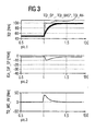
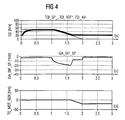
- 3 and 4 are time profiles of the setpoint TQI_SP of the torque with a positive jump in the setpoint TQI_SP, the estimated value TQI_BAS of the maximum torque and an estimate of one actually in the internal combustion engine realized torque, the difference of the reference ignition angle IGA_REF and the setpoint IGA_SP of the Ignition angle and the estimated value TQI_MG_AV of the actual torque applied by the motor generator 5 represented over time t.
- the estimated value TQI_MIN in FIG. 3 the value 20 Nm.
Abstract
Description
Die Erfindung betrifft ein Verfahren gemäß dem Oberbegriff
von Patentanspruch 1 und eine Einrichtung gemäß dem Oberbegriff
des Patentanspruchs 9.The invention relates to a method according to the preamble
of
Ein Verfahren zum Steuern einer Brennkraftmaschine ist aus der DE 196 12 455 A1 bekannt. Ein Sollwert eines Drehmoments wird abhängig von der Fahrpedalstellung eines Fahrpedals, der Drehzahl und weiteren Betriebsgrößen wie dem Luftmassenstrom, der Kühlmitteltemperatur und der Öltemperatur ermittelt. Abhängig von dem Solldrehmoment wird ein Ansteuersignal für einen Drosselklappensteller ermittelt. Das über den Luftmassenstrom einzustellende Drehmoment wird ermittelt unter der Berücksichtigung des Solldrehmoments und Vorhaltewerten des Drehmoments, die von Funktionen zum Steuern der Brennkraftmaschine, wie einer Antriebsschlupfregelung, einer Drehzahlbegrenzung, einer Geschwindigkeitsbegrenzung und einer Katalysator-Heizfunktion, angefordert werden. Ferner ist ein Sollwert des Drehmoments, das schnell einzustellen ist, abhängig von dem Solldrehmoment und Drehmomentanforderungen der weiteren Funktionen zum Steuern der Brennkraftmaschine. Ein Stellsignal für eine Zündkerze ist abhängig von dem Sollwert des Drehmoments. Durch ein Verändern des Zündwinkels kann innerhalb eines Kurbelwellensegments das tatsächlich in einem Zylinder der Brennkraftmaschine erzeugte Drehmoment verändert werden. Die Zeitdauer eines Kurbelwellensegments ist beispielsweise durch den zeitlichen Abstand der Zündungen zweier in der Zündfolge benachbarter Zylinder definiert.A method for controlling an internal combustion engine is off known from DE 196 12 455 A1. A setpoint of a torque becomes dependent on the accelerator pedal position of an accelerator pedal, the Speed and other operating parameters such as air mass flow, the coolant temperature and the oil temperature. Dependent a control signal for a Throttle valve actuator determined. That about the air mass flow The torque to be set is determined taking into account of the target torque and lead values of Torque by functions to control the internal combustion engine, such as traction control, speed limitation, a speed limit and a catalyst heating function, be requested. There is also a setpoint of the torque that can be set quickly from the target torque and torque requirements of the others Functions for controlling the internal combustion engine. An actuating signal for a spark plug depends on the setpoint of the Torque. By changing the ignition angle can be within of a crankshaft segment that is actually in a cylinder the torque generated by the internal combustion engine is changed become. The duration of a crankshaft segment is, for example by the time interval between the ignitions of two defined in the firing order of adjacent cylinders.
Aufgrund der Trägheit des Ansaugtraktes kann der Sollwert des über den Luftmassenstrom einzustellenden Drehmoments nur langsam eingestellt werden. Weist das tatsächlich von der Brennkraftmaschine zu erzeugende Drehmoment eine hohe Dynamik auf, so müssen die Vorhaltewerte groß gewählt werden, um das Drehmoment mit hoher Güte einzustellen. Dies hat jedoch hohe Abgas-Emissionen der Brennkraftmaschine und einen hohen Kraftstoffverbrauch zur Folge.Due to the inertia of the intake tract, the setpoint of the Torque to be set via the air mass flow only be adjusted slowly. Does that actually tell of the Torque to be generated by the internal combustion engine is highly dynamic on, the lead values must be chosen large in order to Set torque with high quality. However, this has high Exhaust emissions from the internal combustion engine and a high Result in fuel consumption.
Aus der den nächstliegenden Stand der Technik bildenden JP-A-09084211 ist ein weiteres Verfahren zum Steuern einer Kraftmaschine, die eine Brennkraftmaschine umfasst, bekannt. Bei diesem Verfahren wird ein Sollwert eines Drehmoments abhängig von einer den Fahrerwunsch repräsentierenden Größe und Betriebsgrößen der Brennkraftmaschine ermittelt. Stellsignale für Stellglieder der Brennkraftmaschine werden ermittelt abhängig von dem Sollwert des Drehmoments. Ein Schätzwert eines maximalen Drehmoments wird ermittelt, dass über die Stellglieder der Brennkraftmaschine innerhalb einer vorgegebenen Zeitdauer einstellbar ist. Die Ermittlung dieses Schätzwertes erfolgt durch Addieren eines Drehmoment-Erhöhungswertes pro vorgegebener Zeitdauer, zu dem in einem vorangegangenen Berechnungszyklus eingestellten alten Drehmomentwert. Ein Stellsignal für einen Motor-Generator wird dann abhängig von dem Sollwert und dem Schätzwert des maximalen Drehmoments ermittelt.From the closest prior art JP-A-09084211 is another method for controlling one An engine comprising an internal combustion engine is known. In this method, a setpoint of a torque is dependent of a size and representing the driver's request Operating variables of the internal combustion engine determined. control signals for actuators of the internal combustion engine are determined dependent from the setpoint of the torque. An estimate of one maximum torque is determined using the actuators the internal combustion engine within a predetermined Time is adjustable. The determination of this estimate is done by adding a torque increase value per predetermined period of time at which in a previous calculation cycle set old torque value. On Control signal for a motor generator is then dependent on the target value and the estimated value of the maximum torque.
Die Aufgabe der Erfindung ist es, eine Einrichtung und ein Verfahren zum Steuern einer Kraftmaschine zu schaffen, die/das einen komfortablen und gleichzeitig emissionsarmen Betrieb der Brennkraftmaschine mit einem hohen Wirkungsgrad der Kraftmaschine gewährleistet und präzise ist.The object of the invention is a device and a To provide methods of controlling an engine which is comfortable and low in emissions Operation of the internal combustion engine with high efficiency the engine is guaranteed and precise.
Die Aufgabe wird durch die Merkmale der unabhängigen Patentansprüche gelöst. Die Erfindung zeichnet sich dadurch aus, daß ein Stellsignal für ein Motorgenerator, der auf der Antriebswelle der Brennkraftmaschine angeordnet ist, abhängig von dem Sollwert des Drehmoments ermittelt wird. Der Motor-Generator hat eine Ansprechzeit, die deutlich niedriger ist als die Zeitdauer bis ein Sprung des Sollwertes des Drehmoments über den Luftmassenstrom eingestellt ist. So können die Vorhaltewerte bei dem über den Luftmassenstrom einzustellenden Drehmoment niedriger gewählt werden ohne dabei Komforteinbußen in Kauf nehmen zu müssen.The object is achieved through the features of the independent claims solved. The invention is characterized in that that a control signal for a motor generator that is on the drive shaft the internal combustion engine is arranged, depending is determined from the nominal value of the torque. The engine generator has a response time that is significantly lower than the length of time until a jump in the setpoint torque is set via the air mass flow. So they can Reserve values for the one to be set via the air mass flow Torque can be selected lower without sacrificing comfort to have to put up with.
Die Erfindung zeichnet sich ferner dadurch aus, dass das Stellsignal für das als Zündkerze oder Einspritzventil ausgebildete Stellglied abhängig ist von einem Sollwert des Drehmoments und dem Schätzwert des tatsächlichen Motor-Generator Drehmoments. Dadurch ist eine äußerst präzise Einstellung des Sollwerts des Drehmoments ermöglicht.The invention is further characterized in that the Control signal for that designed as a spark plug or injection valve Actuator depends on a setpoint of the torque and the estimate of the actual motor generator Torque. This is an extremely precise adjustment of the Torque setpoint enabled.
Vorteilhafte Ausgestaltungen der Erfindung sind in den Unteransprüchen gekennzeichnet. Ein Ausführungsbeispiel der Erfindung ist im folgenden unter Bezugnahme auf die schematischen Zeichnungen näher erläutert. Es zeigen:
Figur 1- eine Kraftmaschine mit einer Brennkraftmaschine und einem Motor-Generator,
Figur 2- a bis c Blockschaltbilder der erfindungsgemäßen Steuerung,
Figur 3, 4- Signalverläufe aufgetragen über die Zeit t.
- Figure 1
- an engine with an internal combustion engine and a motor generator,
- Figure 2
- a to c block diagrams of the control according to the invention,
- Figures 3, 4
- Waveforms plotted over time t.
Elemente gleicher Konstruktion und Funktion sind figurenübergreifend mit den gleichen Bezugszeichen versehen.Elements of the same construction and function are common to all figures provided with the same reference numerals.
Eine Kraftmaschine (Figur 1) umfaßt eine Brennkraftmaschine.
Die Brennkraftmaschine hat einen Ansaugtrakt 1 mit einer
Drosselklappe 10 und einem Motorblock 2, der einen Zylinder
20 und eine Kurbelwelle 23 aufweist. Ein Kolben 21 und eine
Pleuelstange 22 sind dem Zylinder 20 zugeordnet. Die Pleuelstange
22 ist mit dem Kolben 21 und der Kurbelwelle 23 verbunden.An engine (Figure 1) includes an internal combustion engine.
The internal combustion engine has an
Ein Zylinderkopf 3 ist vorgesehen, in dem ein Ventiltrieb angeordnet
ist mit mindestens einem Einlaßventil 30, einem Auslaßventil
31 und jeweils einem dem Einlaßventil 30 zugeordneten
Ventilantrieb 32a und einem dem Auslaßventil 31 zugeordneten
Ventilantrieb 32b.A
In den Ansaugtrakt 1 ist ein Einspritzventil 11 eingebracht,
das so angeordnet ist, daß der Kraftstoff in den Ansaugtrakt
1 zugemessen wird. Das Einspritzventil 11 kann alternativ
auch in dem Zylinderkopf 3 eingebracht sein und dort so angeordnet
sein, daß der Kraftstoff direkt in den Innenraum des
Zylinders 20 zugemessen wird. Eine Zündkerze 34 ist in eine
Ausnehmung des Zylinderkopfes 3 eingebracht. Die Brennkraftmaschine
ist in der Figur 1 mit einem Zylinder dargestellt.
Sie kann jedoch auch mehrere Zylinder umfassen.An injection valve 11 is introduced into the
Ein Abgastrakt 4 ist der Brennkraftmaschine zugeordnet. Ein
Motor-Generator 5 ist vorgesehen, dessen Rotor kraftschlüssig
mit der Kurbelwelle 23 verbunden ist. Der Motor-Generator ist
vorzugsweise als Asynchron-Maschine ausgebildet. Er kann jedoch
auch als Synchron-Maschine oder als Gleichstrommotor
ausgebildet sein. Die Kurbelwelle 23 ist im Motorbetrieb die
Abtriebswelle des Motor-Generators und im Generatorbetrieb
die Antriebswelle des Motor-Generators. Der Motor-Generator 5
ersetzt den Starter und den sonst üblichen Generator einer
Brennkraftmaschine. Die Kraftmaschine ist somit wesentlich
kompakter.An exhaust tract 4 is assigned to the internal combustion engine. On
Motor-
Die Kurbelwelle 23 ist über eine Kupplung 6 mit einem nicht
dargestellten Getriebe koppelbar. Wenn das Getriebe als Automatikgetriebe
ausgebildet ist, dann ist die Kupplung 6 beispielsweise
als Wandlerüberbrückungskupplung vorzugsweise mit
einem hydrodynamischen Wandler ausgebildet.The
Eine Steuereinrichtung 7 für die Kraftmaschine ist vorgesehen, der Sensoren zugeordnet sind, die verschiedene Meßgrößen erfassen und jeweils den Meßwert der Meßgröße ermitteln. Die Steuereinrichtung 7 ermittelt abhängig von mindestens einer Betriebsgröße ein oder mehrere Stellsignale, die ein Stellgerät steuern.A control device 7 for the engine is provided, the sensors are assigned to the various measured variables record and determine the measured value of the measured variable. The Control device 7 determines depending on at least one Operating variable one or more control signals that an actuator Taxes.
Die Sensoren sind ein Pedalstellungsgeber 81, der eine Pedalstellung
PV des Fahrpedals 8 erfaßt, ein Drosselklappenstellungsgeber
12, der einen Öffnungsgrad der Drosselklappe erfaßt,
ein Luftmassenmesser 13, der einen Luftmassenstrom erfaßt
und/oder ein Saugrohrdrucksensor 14, der einen Saugrohrdruck
in dem Ansaugtrakt 1 erfaßt, ein erster Temperatursensor
15 der eine Ansauglufttemperatur erfaßt, ein Drehzahlgeber
24, der eine Drehzahl N der Kurbelwelle 23 erfaßt, und
ein zweiter und dritter Temperatursensor 26, 27, die eine Öltemperatur
TOIL beziehungsweise eine Kühlmitteltemperatur TCO
erfassen. Ferner ist eine Meßeinheit 51 vorgesehen, die eine
charakteristische Betriebsgröße des Motor-Generators 5 erfaßt.
Die charakteristische Betriebsgröße des Motor-Generators
5 kann beispielsweise ein Strom oder eine Spannung
oder eine Leistung sein. Der Steuereinrichtung 7 kann eine
beliebige Untermenge der genannten Sensoren zugeordnet sein,
es können hier aber auch zusätzliche Sensoren zugeordnet
sein.The sensors are a
Betriebsgrößen umfassen Meßgrößen sowie von diesen abgeleitete Größen, die über einen Kennfeldzusammenhang oder von einem Beobachter ermittelt werden, der Schätzwerte der Betriebsgrößen berechnet.Operating variables include measured variables and those derived from them Sizes that are related to or from a map Observers are determined, the estimates of the farm sizes calculated.
Die Stellgeräte umfassen jeweils einen Stellantrieb und ein
Stellglied. Der Stellantrieb ist ein elektromotorischer Antrieb,
eine elektromagnetischer Antrieb, ein mechanischer
oder ein weiterer dem Fachmann bekannter Antrieb. Die Stellglieder
sind als Drosselklappe 10, als Einspritzventil 11,
als Zündkerze 34 oder als sonstige dem Fachmann bei Brennkraftmaschinen
bekannte Stellglieder ausgebildet. Auf die
Stellgeräte wird im folgenden mit dem jeweils zugeordneten
Stellglied bezug genommen.The actuators each include an actuator and a
Actuator. The actuator is an electric motor drive,
an electromagnetic drive, a mechanical one
or another drive known to the person skilled in the art. The actuators
are as a
Die Steuereinrichtung ist vorzugsweise als elektronische Motorsteuerung ausgebildet. Sie kann jedoch auch mehrere Steuergeräte umfassen, die elektrisch leitend miteinander verbunden sind, so z.B. bei einem Bussystem.The control device is preferably an electronic engine control educated. However, it can also have several control units include the electrically connected together are, e.g. with a bus system.
Im folgenden wird die Funktion des erfindungsrelevanten Teils
der Steuereinrichtung 7 anhand der Blockschaltbilder der Figuren
2a, 2b, 2c beschrieben. Ein Schätzwert MAF_CYL (siehe
Figur 2a) des Luftmassenstrom in den Zylinder 20 wird mit einem
Füllungsmodell des Ansaugtraktes 1 abhängig von dem Meßwert
MAF_MES des Luftmassenstroms und weiteren Betriebsgrößen
berechnet. Ein derartiges Modell ist in der WO 96/32579 offenbart,
deren Inhalt hiermit diesbezüglich einbezogen ist.The following is the function of the part relevant to the invention
the control device 7 using the block diagrams of the figures
2a, 2b, 2c. An estimate of MAF_CYL (see
Figure 2a) of the air mass flow in the
Ein Kennfeld KF1 ist vorgesehen, aus dem ein erster Beitrag
TQFR zu einem Verlustdrehmoment TQ_LOSS abhängig von der
Drehzahl N, und dem Schätzwert MAF_CYL des Luftmassenstroms
im Zylinder 20 ermittelt wird. Der erste Beitrag TQFR zu dem
Verlustdrehmoment TQ_LOSS berücksichtigt Pumpverluste in der
Brennkraftmaschine und Verluste, die durch Reibung bei vorgegebenen
Referenzwerten der Kühlmitteltemperatur TCO und der
Öltemperatur TOIL auftreten.A map KF1 is provided, from which a first contribution
TQFR to a loss torque TQ_LOSS depending on the
Speed N, and the estimated value MAF_CYL of the air mass flow
is determined in the
Ein zweiter Beitrag TQFR_ADD zu dem Verlustdrehmoment TQ_LOSS
wird aus einem Kennfeld KF2 abhängig von der Öltemperatur
TOIL und/oder der Kühlmitteltemperatur TCO ermittelt. Ferner
wird ein dritter Beitrag TQ_LOSS_MG zum Verlustdrehmoment abhängig
von dem Meßsignal M_MG, das von der Meßeinheit 51 erzeugt
wird, ermittelt. Der dritte Beitrag TQ_LOSS_MG zum Verlustdrehmoment
TQ_LOSS wird in einem Block B1 über ein dynamisches
Modell der Verluste des Motor-Generators ermittelt.
Vorzugsweise umfaßt das dynamische Modell der Verluste des
Motor-Generators 5 eine Kennlinie, in der Kennwerte des dritten
Beitrags TQ_LOSS_MG abhängig von einem erfaßten Strom
durch den Motor-Generator 5 abgelegt sind. Die Kennwerte werden
mit einem Korrekturfaktor korrigiert, der abhängt von der
Temperatur des Motor-Generators, wobei dieser Korrekturfaktor
vorzugsweise einer PD1-Filterung unterzogen wird. Die Temperatur
des Motor-Generators wird entweder direkt ermittelt
oder aus einem Kennfeld abhängig von der zu- oder abgeführten
Leistung des Motor-Generators ermittelt. Vorzugsweise wird
bei der Korrektur des dritten Beitrages TQ_LOSS_MG zum Verlustdrehmoment
TQ_LOSS auch die Ansaugtemperatur berücksichtigt.
Die Beiträge TQFR, TQFR_ADD, TQ_LOSS_MG werden in einem
Verknüpfungspunkt V1 addiert. Ihre Summe bildet dann das Verlustdrehmoment
TQ_LOSS.A second contribution TQFR_ADD to the loss torque TQ_LOSS is determined from a map KF2 depending on the oil temperature TOIL and / or the coolant temperature TCO. Furthermore, a third contribution TQ_LOSS_MG to the loss torque is determined as a function of the measurement signal M_MG that is generated by the
In einem Block B2 wird ein zur Verfügung stellbarer Drehmomentbereich abhängig von dem Verlustdrehmoment TQ_LOSS und der Drehzahl N ermittelt. Aus der Fahrpedalstellung PV und der Drehzahl N wird ermittelt, welcher Anteil des zur Verfügung stellbaren Drehmomentbereichs von dem Fahrer angefordert wird. Aus dem angeforderten Anteil des Drehmoments und dem zur Verfügung stellbaren Drehmoment wird dann ein dem Fahrerwunsch entsprechender Wert TQI_REQ des Drehmoments ermittelt. Dabei ist vorzugsweise auch eine Filterung des dem Fahrerwunsch entsprechenden Wertes TQI_REQ des Drehmoments vorgesehen, um sicherzustellen, daß keine Lastsprünge auftreten können, die zu einem unangenehmen Ruckeln des Fahrzeugs führen, in dem die Kraftmaschine angeordnet ist.In block B2 there is an available torque range depending on the loss torque TQ_LOSS and the speed N determined. From the accelerator pedal position PV and the speed N is determined, what proportion of the available adjustable torque range requested by the driver becomes. From the requested portion of the torque and the The torque that can be made available is then a driver's request corresponding value TQI_REQ of the torque is determined. Filtering of the driver's request is also preferred corresponding value TQI_REQ of the torque is provided, to ensure that no load jumps can occur, which lead to an uncomfortable jerking of the vehicle, in which the engine is arranged.
In einem Block B3 wird ein Sollwert TQI_SP_MAF des über den Luftmassenstrom einzustellenden Drehmoments ermittelt. Dabei werden neben dem Wert TQI_REQ des Drehmoments Vorhaltewerte berücksichtigt. So wird beispielsweise ein Vorhaltewert TQI_IS von einem Leerlaufregler vorgegeben, ein Vorhaltewert TQI_CH von einer Funktion zum Aufheizen eines Katalysators vorgegeben, ein Vorhaltewert TQI_ASC von einer Anti-Schlupfregelung vorgegeben, ein Vorhaltewert TQI_N_MAX von einer Funktion zur Drehzahlbegrenzung vorgegeben, oder ein Vorhaltewert TQI_MSR von einer Motorschleppmomentregelung vorgegeben. Der Sollwert TQI_SP_MAF des über den Luftmassenstrom einzustellenden Drehmoments kann somit größer oder kleiner sein als der Wert TQI_REQ des Drehmoments, der dem Fahrerwunsch entspricht.In a block B3, a setpoint TQI_SP_MAF of the Determined air mass flow torque. there in addition to the value TQI_REQ of the torque, lead values considered. For example, a lead value TQI_IS specified by an idle controller, a lead value TQI_CH of a function for heating a catalytic converter specified, a lead value TQI_ASC from an anti-slip control specified, a lead value TQI_N_MAX of a function for speed limitation, or a Lead value TQI_MSR from a motor drag torque control specified. The setpoint TQI_SP_MAF of the air mass flow Torque to be set can thus be greater or be less than the value TQI_REQ of the torque corresponding to the Driver request corresponds.
Über ein Kennfeld KF3 wird dem Sollwert TQI_SP_MAF des über den Luftmassenstrom einzustellenden Drehmoments abhängig von der Drehzahl N ein Sollwert MAF_SP des Luftmassenstroms zugeordnet. Die Werte des Kennfelds KF3 sind aus Messungen an einem Motorprüfstand bei einer Referenz-Luftzahl LAM_REF und bei einem Referenz-Zündwinkel IGA_REF abgeleitet oder durch eine Simulationsrechnung ermittelt.The setpoint TQI_SP_MAF of the is via a map KF3 the air mass flow to be set depending on a nominal value MAF_SP of the air mass flow is assigned to the speed N. The values of the map KF3 are from measurements on one Engine test bench with a reference air ratio LAM_REF and at a reference ignition angle IGA_REF derived or by a simulation calculation is determined.
In einem Block B4 wird ein Sollwert THR_SP des Öffnungsgrades
der Drosselklappe 10 abhängig von dem Sollwert MAF_SP des
Luftmassenstroms ermittelt. In einem Block B5 wird ein Stellsignal
zum Ansteuern der Drosselklappe 10 ermittelt, vorzugsweise
von einem Lageregler der Drosselklappe 10.In a block B4, a setpoint THR_SP of the degree of opening
of the
Der Sollwert TQI_SP_MAF des über den Luftmassenstrom einzustellenden Drehmoments berücksichtigt vorausschauend das unter der Berücksichtigung der Dynamik des Ansaugtraktes einzustellende Drehmoment.The setpoint TQI_SP_MAF to be set via the air mass flow Torque anticipates this under taking into account the dynamics of the intake tract Torque.
In einem Block B6 wird ein Sollwert TQI_SP des Drehmoments ermittelt, der innerhalb einer vorgegebenen Zeitdauer einzustellen ist. Die vorgegebene Zeitdauer entspricht vorzugsweise der Zeitdauer, die durch ein Kurbelwellensegment bestimmt ist. Ein Kurbelwellensegment ist bestimmt durch den Winkel zwischen zwei oberen Totpunkten zweier in der Zündfolge benachbarter Zylinder oder auch durch den Zündabstand zweier in der Zündfolge benachbarter Zylinder. Der Sollwert TQI_SP des Drehmoments muß demnach sehr schnell, also z.B. innerhalb eines Arbeitsspiels der Brennkraftmaschine, einstellbar sein.In a block B6, a setpoint TQI_SP of the torque determined to set within a predetermined period of time is. The predetermined time period preferably corresponds the length of time determined by a crankshaft segment is. A crankshaft segment is determined by the angle between two top dead centers of two neighboring in the firing order Cylinder or even by the ignition interval of two in the firing order of neighboring cylinders. The setpoint TQI_SP of the Torque must therefore be very fast, e.g. within a Working cycle of the internal combustion engine to be adjustable.
In einem Block B6 wird der Sollwert TQI_SP des Drehmoments abhängig von dem dem Fahrerwunsch entsprechenden Wert TQI_REQ des Drehmoments und Drehmomentanforderungen TQI_ASC_FAST, TQI_GS_FAST, TQI_N_MAX_FAST einer Anti-Schlupfregelung, einer Getriebesteuerung und einer Funktion zur Begrenzung der Drehzahl N berechnet. Daneben können auch weitere Drehmomentanforderungen berücksichtigt werden.In a block B6, the setpoint TQI_SP of the torque depending on the value TQI_REQ corresponding to the driver's request of the torque and torque requirements TQI_ASC_FAST, TQI_GS_FAST, TQI_N_MAX_FAST an anti-slip control, one Transmission control and a function to limit the speed N calculated. In addition, other torque requirements can also be met be taken into account.
Das Ermitteln eines Schätzwertes TQI_BAS des maximalen Drehmoments, das innerhalb der vorgegebenen Zeitdauer eingestellt werden kann, wird im folgenden anhand von Figur 2b erläutert. Ein Kennfeld KF4 ist vorgesehen, aus dem abhängig von dem Schätzwert MAF_CYL und der Drehzahl N ein Referenzwert TQI_REF des Drehmoments ermittelt wird. Die Werte des Kennfelds KF4 sind aus Messungen an einem Motorprüfstand bei einer Referenz-Luftzahl LAM_REF und bei einem Referenz-Zündwinkel IGA_REF abgeleitet oder durch eine Simulationsrechnung ermittelt. Der Referenzwert TQI_REF des Drehmoments ist demnach jeweils das Drehmoment, das bei der entsprechenden Drehzahl und dem entsprechenden Luftmassenstrom in den Zylinder maximal theoretisch realisiert werden kann, wenn gleichzeitig der Wirkungsgrad EFF_IGA bezogen auf den Zündwinkel und der Wirkungsgrad EFF_LAM bezogen auf die Luftzahl maximal sind.Determining an estimate TQI_BAS of the maximum Torque set within the specified time can be explained below with reference to Figure 2b. A map KF4 is provided, from which depends from the estimated value MAF_CYL and the speed N a reference value TQI_REF of the torque is determined. The values of Kennfelds KF4 are from measurements on an engine test bench a reference air ratio LAM_REF and at a reference ignition angle IGA_REF derived or by a simulation calculation determined. The reference value TQI_REF of the torque is therefore always the torque that the corresponding Speed and the corresponding air mass flow in the Cylinder can theoretically be realized at maximum if at the same time the efficiency EFF_IGA related to the ignition angle and the efficiency EFF_LAM based on the air ratio are maximum.
In einem Kennfeld KF5 wird der Referenz-Zündwinkel IGA_REF
abhängig von der Drehzahl, dem Schätzwert MAF_CYL des Luftmassenstroms
im Zylinder 20 und der Kühlmitteltemperatur TCO
ermittelt.The reference ignition angle IGA_REF is shown in a map KF5
depending on the speed, the estimated value MAF_CYL of the air mass flow
in the
In einem Kennfeld KF6 wird ein pareto-optimaler Basis-Zündwinkel
IGA_BAS abhängig von der Drehzahl N, dem Schätzwert
MAF_CYL des Luftmassenstroms in den Zylinder 20 und der
Kühlmitteltemperatur TCO ermittelt.In a map KF6 there is a pareto-optimal basic ignition angle
IGA_BAS depending on the speed N, the estimated value
MAF_CYL of the air mass flow in the
In einem Verknüpfungspunkt V2 wird die Differenz des Basis-Zündwinkels IGA_BAS und des Referenz-Zündwinkels IGA_REF gebildet. In einem Block B8 wird dann abhängig von dieser Differenz der Wirkungsgrad EFF_IGA des Zündwinkels ermittelt. Der Wirkungsgrad EFF_IGA des Zündwinkels ist normiert auf den Wirkungsgrad des Zündwinkels bei dem Referenz-Zündwinkel IGA_REF.At a node V2, the difference in the basic ignition angle IGA_BAS and the reference ignition angle IGA_REF formed. In block B8, this difference then becomes dependent the efficiency EFF_IGA of the ignition angle is determined. The efficiency EFF_IGA of the ignition angle is standardized to the Efficiency of the ignition angle at the reference ignition angle IGA_REF.
Die Referenz-Luftzahl LAM_REF wird aus einem Kennfeld KF7 abhängig
von der Drehzahl N und dem Schätzwert MAF_CYL des
Luftmassenstroms in den Zylinder 20 ermittelt. Eine paretooptimaler
Basis-Luftzahl LAM_BAS wird aus einem Kennfeld KF8
abhängig von der Drehzahl N und einem Schätzwert MAF_CYL des
Luftmassenstroms in den Zylinder 20 ermittelt. In einem Verknüpfungspunkt
V3 wird die Differenz der Basis-Luftzahl
LAM_BAS und der Referenz-Luftzahl LAM_REF gebildet und dann
im Block B9 der Wirkungsgrad EFF_LAM der Luftzahl normiert
auf den Wirkungsgrad bei der Referenz-Luftzahl LAM_REF ermittelt.The reference air ratio LAM_REF is dependent on a map KF7
of the speed N and the estimated value MAF_CYL des
Air mass flow in the
In einem Block B10 wird der Schätzwert TQI_BAS des maximalen
Drehmoments aus dem Produkt des Referenzwertes TQI_REF des
Drehmoments des Wirkungsgrades EFF_IGA des Zündwinkels und
des Wirkungsgrades EFF_LAM der Luftzahl ermittelt. Der
Schätzwert TQI_BAS des maximalen Drehmoments ist demnach der
höchste Wert des Drehmoments, der tatsächlich bei einem gegebenen
Schätzwert MAF_CYL des Luftmassenstroms in den Zylinder
20, der Drehzahl N und der Kühlmitteltemperatur durch die
Brennkraftmaschine aufgebracht werden kann. Der Basiswert
TQI_BAS des Drehmoments ist somit immer kleiner oder gleich
dem Referenzwert TQI_REF des Drehmoments.In block B10, the estimated value TQI_BAS is the maximum
Torque from the product of the reference value TQI_REF des
Torque of the efficiency EFF_IGA of the ignition angle and
of the EFF_LAM efficiency of the air ratio. The
Estimated value TQI_BAS of the maximum torque is therefore the
highest value of the torque actually at a given
MAF_CYL estimate of the air mass flow into the
Zum Ermitteln eines Schätzwertes TQI_MIN (Figur 2c) des minimalen Drehmoments wird im Unterschied zu der Ermittlung des Schätzwertes TQI_BAS des maximalen Drehmoments aus einem Kennfeld KF10 ein Minimal-Zündwinkel IGA_MIN abhängig von der Drehzahl N, dem Schätzwert MAF_CYL und der Kühlmitteltemperatur TCO ermittelt, und dann in dem Verknüpfungspunkt V2 die Differenz des Minimal-Zündwinkels IGA_MIN und des Referenz-Zündwinkels IGA_REF gebildet.To determine an estimate TQI_MIN (Figure 2c) of the minimum Torque is different from the determination of the Estimated value TQI_BAS of the maximum torque from one Map KF10 a minimum ignition angle IGA_MIN depending on the Speed N, the estimated value MAF_CYL and the coolant temperature TCO determined, and then in node V2 the Difference between the minimum ignition angle IGA_MIN and the reference ignition angle IGA_REF formed.
Ferner wird in einem Kennfeld KF11 eine Minimal-Luftzahl LAM_MIN abhängig von der Drehzahl und dem Schätzwert MAF_CYL des Luftmassenstroms in den Zylinder 20 eine Minimal-Luftzahl LAM_MIN ermittelt. In dem Verknüpfungspunkt V3 wird dann die Differenz der Minimal-Luftzahl LAM_MIN und der Referenz-Luftzahl LAM_REF gebildet. Ferner wird in einem Block B12 ein Zylinderabschaltungs-Wirkungsgrad EFF_SCC abhängig von der Anzahl der im Schubbetrieb der Brennkraftmaschine abgeschalteten Zylinder ermittelt. Furthermore, a minimum air ratio is shown in a map KF11 LAM_MIN depending on the speed and the estimated value MAF_CYL of the air mass flow in the cylinder 20 a minimum air ratio LAM_MIN determined. In node V3 the Difference between the minimum air ratio LAM_MIN and the reference air ratio LAM_REF formed. Furthermore, in a block B12 Cylinder deactivation efficiency EFF_SCC depending on the Number of shutdowns in the overrun mode of the internal combustion engine Cylinder determined.
Der Schätzwert TQI_MIN des minimalen Drehmoments wird dann in
dem Block B13 durch Bildung des Produkts aus dem Referenzwert
des Drehmoments TQI_REF, des Wirkungsgrades EFF_IGA des Zündwinkels,
des Wirkungsgrades EFF_LAM der Luftzahl und des Wirkungsgrades
EFF_SCC der Zylinderabschaltung ermittelt. Der
Schätzwert TQI_MIN des minimalen Drehmoments ist demnach der
niedrigste Wert des Drehmoments, der tatsächlich bei einem
gegebenen Schätzwert MAF_CYL des Luftmassenstroms in den Zylinder
20, der Drehzahl N und der Kühlmitteltemperatur durch
die Brennkraftmaschine aufgebracht werden kann.The minimum torque estimate TQI_MIN is then in
block B13 by forming the product of the reference value
the torque TQI_REF, the efficiency EFF_IGA, the ignition angle,
the efficiency EFF_LAM, the air ratio and the efficiency
EFF_SCC of cylinder deactivation determined. The
The estimated value TQI_MIN of the minimum torque is therefore the
lowest value of the torque that is actually at one
given estimate MAF_CYL of the air mass flow into the
In einer Verknüpfungsstelle V6 (Figur 2a) wird die Differenz des Sollwertes TQI_SP des Drehmoments und des Schätzwertes TQI_BAS des maximalen Drehmomentes ermittelt. In einem Block B15 wird diese Differenz auf einen vorgegebenen unteren Schwellenwert begrenzt. Der untere Schwellenwert kann besonders einfach gleich Null gewählt werden. Er kann ebenso kleiner Null gewählt werden oder auch abhängig von der Temperatur des Motor-Generators oder dem Beladungsgrad einer Spannungsversorgung (Batterie) des Fahrzeugs, in dem die Kraftmaschine angeordnet ist, bestimmt werden. So kann auf einfache Weise die Verfügbarkeit des Motor-Generators, d. h. die Zeit zwischen zwei Ausfällen des Motor-Generators erhöht werden. Ebenso kann so der Ladezustand der Batterie auf einem vorgegebenen vorteilhaften Wert gehalten werden.In a connection point V6 (Figure 2a), the difference the setpoint TQI_SP of the torque and the estimated value TQI_BAS of the maximum torque determined. In one block B15 will lower this difference to a predetermined one Threshold limited. The lower threshold can be special simply be chosen to be zero. It can also be smaller Be selected zero or depending on the temperature of the motor generator or the degree of loading of a voltage supply (Battery) of the vehicle in which the engine is arranged to be determined. This can be done in a simple way the availability of the motor generator, d. H. the time between two failures of the motor generator are increased. The state of charge of the battery can also be set to a predetermined level advantageous value can be kept.
In einem Verknüpfungspunkt V7 wird die Differenz des Sollwertes
TQI_SP des Drehmoments und des Schätzwertes TQI_MIN des
minimalen Drehmoments gebildet. In einem Block B16 erfolgt
dann die Begrenzung dieser Differenz auf einen oberen Schwellenwert
der entweder den fest vorgegebenen Wert Null oder einen
fest vorgegebenen Wert größer Null oder einen Wert hat,
der abhängt von der Temperatur des Motor-Generators 5 oder
dem Beladungsgrad der Batterie. The difference in the setpoint is shown in a node V7
TQI_SP of the torque and the estimated value TQI_MIN of the
minimum torque is formed. In a block B16
then limiting this difference to an upper threshold
which is either the fixed value zero or one
has a predetermined value greater than zero or has a value
which depends on the temperature of the
In einem Verknüpfungspunkt V8 wird dann die Summe der Ausgangsgrößen
der Blöcke B15 und B16 gebildet und einem Sollwert
TQ_MG_SP des durch den Motor-Generator 5 aufzubringenden
Drehmoments zugeordnet. In einem Block B18 wird dann ein
Stellsignal S_MG für den Motor-Generator 5 über ein physikalisches
Modell des Motor-Generators abhängig von dem Sollwert
TQ_MG_SP des durch den Motor-Generator aufzubringenden
Drehmoments, der Temperatur des Motor-Generators 5 und der
Drehzahl N erzeugt.The sum of the output variables is then at a node V8
of blocks B15 and B16 and a setpoint
TQ_MG_SP of the
Das physikalische Modell umfaßt beispielsweise eine Kennlinie
aus der abhängig von dem Sollwert TQ_MG_SP des durch den Motor-Generator
5 aufzubringenden Drehmoments das Stellsignal
S_MG des Motor-Generators ermittelt wird. Das Stellsignal
S_MG des Motor-Generators 5 wird dann noch abhängig von einem
Korrekturwert multiplikativ korrigiert. Der Korrekturwert
wird aus einem Kennfeld abhängig von der Temperatur des Motor-Generators
5 und der Drehzahl N ermittelt und dann einer
PD1-Filertung unterzogen. Ein derartiges Modell beschreibt
das dynamische Verhalten des Motor-Generators hinreichend genau.The physical model comprises, for example, a characteristic curve from which the control signal S_MG of the motor generator is determined depending on the setpoint TQ_MG_SP of the torque to be applied by the
Mit dem Stellsignal S_MG wird der Motor-Generator 5 angesteuert.
Das Stellsignal S_MG kann entweder ein Strom durch die
Wicklungen des Motor-Generators 5 oder eine Spannung sein.
Der entscheidende Signalparameter ist entweder die Amplitude
oder die Frequenz der Spannung oder des Stroms.The
In dem Block B19 wird ein Schätzwert TQ_MG_AV des durch den
Motor-Generator 5 aufgebrachten Drehmoments über das zu dem
in dem Block B18 beschriebene inverse physikalische Modell
des Motor-Generators ermittelt. Dabei erfolgt die Ermittlung
des Schätzwertes TQ_MG_AV des durch den Motor-Generator aufgebrachten
Drehmoments abhängig von dem Meßsignal M_MG des
Motor-Generators, das beispielsweise die Spannung oder der
Strom durch den Motor-Generator 5 ist.In block B19, an estimate TQ_MG_AV of the by
Motor-
In einem Verknüpfungspunkt V8 wird die Differenz des Sollwertes
TQI_SP des Drehmoments und des Schätzwertes TQ_MG_AV des
tatsächlich durch den Motor-Generator aufgebrachten Drehmoments
ermittelt. Die in dem Verknüpfungspunkt V8 ermittelte
Differenz stellt demnach den Anteil des Sollwertes TQI_SP des
Drehmoments dar, der durch den Motor-Generator 5 nicht aufgebracht
wird.The difference in the setpoint is shown in a node V8
TQI_SP of the torque and the estimated value TQ_MG_AV of the
torque actually applied by the motor generator
determined. The determined in node V8
Difference therefore represents the proportion of the setpoint TQI_SP
Torque represents that is not applied by the
In einem Block B20 wird der Quotient, der in dem Verknüpfungspunkt
V8 ermittelten Differenz und des Referenzwertes
TQI_REF des Drehmoments ermittelt. Der Quotient ist dann Eingangsgröße
einer Kennlinie in einem Block B21, aus der ein
Sollwert IGA_SP des Zündwinkels ermittelt wird. Die Zündkerze
34 wird dann entsprechend des Sollwertes IGA_SP des Zündwinkels
angesteuert.In a block B20, the quotient that is in the node
V8 determined difference and the reference value
TQI_REF of the torque determined. The quotient is then the input variable
a characteristic curve in a block B21, from which a
Setpoint IGA_SP of the ignition angle is determined. The
Die Steuereinrichtung 7 zeichnet sich dadurch aus, daß die
Vorhaltewerte TQI_IS, TQI_CH, TQI_ASC und TQI_N_MAX niedrig
gewählt werden können, da bei einer tatsächlichen Anforderung
dieses Drehmoments, also bei hoher Dynamik des Sollwertes
TQI_SP eine schnelle Einstellung zusätzlich über den Motor-Generator
5 erfolgen kann, dessen Ansprechzeit wesentlich
niedriger ist als die Ansprechzeit des Ansaugtraktes auf Änderungen
der Drosselklappenstellung.The control device 7 is characterized in that the
Reserve values TQI_IS, TQI_CH, TQI_ASC and TQI_N_MAX low
can be chosen because of an actual requirement
of this torque, i.e. with a high dynamic of the setpoint
TQI_SP quick adjustment via the
Durch eine geeignete Wahl des oberen und unteren Schwellenwertes
in den Blöcken B16 und B17 kann zudem gewährleistet
werden, daß auch beim instationären Betrieb der Kraftmaschine
ein Drehmomentvorhalt TQI_CH bestehen bleibt, um hohe Abgastemperaturen
zum Aufheizen des Katalysators zu gewährleisten.
Über den Motor-Generator kann jeweils das über eine
Verstellung des Zündwinkels nicht zu erreichende Änderung des
Drehmoments erreicht werden. Darüber hinaus erfolgt eine präzise
Einstellung des Sollwertes TQI_SP des Drehmoments über
das Stellglied Zündkerze 34. Ferner kann bei negativen Sprüngen
des Sollwertes TQI_SP ein Aufladen der Batterie des Fahrzeugs
erfolgen, statt einer Umwandlung in Verlustwärme.By a suitable choice of the upper and lower threshold
in blocks B16 and B17 can also be guaranteed
be that even during transient operation of the engine
a torque reserve TQI_CH remains at high exhaust gas temperatures
to ensure heating of the catalyst.
The motor generator can do that in each case
Adjustment of the ignition angle not possible change of the
Torque can be achieved. In addition, there is a precise
Setting the setpoint TQI_SP of the torque via
the
Anhand der Figuren 3 und 4 sind Zeitverläufe des Sollwertes
TQI_SP des Drehmoments bei einem positiven Sprung des Sollwertes
TQI_SP, des Schätzwertes TQI_BAS des maximalen Drehmoments
und eines Schätzwertes eines tatsächlich in der Brennkraftmaschine
realisierten Drehmoments, der Differenz des Referenz-Zündwinkels
IGA_REF und des Sollwertes IGA_SP des
Zündwinkels und des Schätzwertes TQI_MG_AV des tatsächlichen
durch den Motor-Generator 5 aufgebrachten Drehmoments aufgetragen
über die Zeit t dargestellt. Die gleichen Größen wie
in Figur 3 sind auch in Figur 4 aufgetragen über die Zeit t
wobei hier der Sollwert TQI_SP des Drehmoments ab dem Zeitpunkt
T = 1 s von einem stationären Wert (50 Nm) auf den Wert
Null Nm sich verändert. Der Schätzwert TQI_MIN hat in Figur 3
den Wert 20 Nm.3 and 4 are time profiles of the setpoint
TQI_SP of the torque with a positive jump in the setpoint
TQI_SP, the estimated value TQI_BAS of the maximum torque
and an estimate of one actually in the internal combustion engine
realized torque, the difference of the reference ignition angle
IGA_REF and the setpoint IGA_SP of the
Ignition angle and the estimated value TQI_MG_AV of the actual
torque applied by the
Claims (7)
- Method for controlling a prime mover which comprises an internal combustion engine, wherebycharacterised in thata required value (TQI_SP) for a torque is dependent on a variable representing the driver's request and on operational variables relating to the internal combustion engine,actuating signals for actuators in the internal combustion engine are dependent on the required value (TQI_SP) for the torque,an estimated value (TQI_BAS, TQI_MIN) for a maximum or minimum torque is determined, which can be set by way of the actuators in the internal combustion engine within a predefined period of time,an actuating signal (S_MG) for a motor-generator set (5), which is located on the output shaft of the internal combustion engine, is dependent on the required value (TQI_SP) and the estimated value (TQI_BAS, TQI_MIN) for the maximum or minimum torque,an estimated value (TQ_MG_AV) for the actual motor-generator set torque is determined,an actuating signal for the actuator which takes the form of a spark plug (34) or injection valve (11) is a function of the required value (TQI_SP) for the torque and the estimated value (TQ_MG_AV) for the actual motor-generator set torque.
- Method according to Claim 1, characterised in that the actuating signal (S_MG) for the motor-generator set (5) is a function of the difference between the required value (TQI_SP) for the torque and the estimated value (TQI_BAS, TQI_MIN) for the maximum or minimum torque.
- Method according to one of the Claims 1 or 2, characterised in that the motor-generator set (5) is operated as a motor when the estimated value (TQI_BAS) for the maximum torque is less than the required value (TQI_SP) for the torque.
- Method according to one of the Claims 1 to 3, characterised in that the motor-generator set (5) is operated as a generator when the estimated value (TQI_MIN) for the minimum torque is greater than the required value (TQI_SP) for the torque.
- Method according to one of the Claims 1 to 4, characterised in that the motor-generator set (5) is operated as a motor when the difference between the required value (TQI_SP) for the torque and the estimated value (TQI_BAS) for the maximum torque is greater than a predefined threshold value.
- Method according to one of the Claims 1 to 5, characterised in that the predefined duration is defined by the duration of a crankshaft segment.
- Device for controlling a prime mover which comprises an internal combustion engine, wherebycharacterised in thatmeans are provided for determining a required value (TQI_SP) for a torque as a function of a variable representing the driver's request and of operational variables relating to the internal combustion engine,means are provided for generating actuating signals for actuators in the internal combustion engine as a function of the required value (TQI_SP) for the torque,means are provided for determining an estimated value (TQI_BAS, TQI_MIN) for a maximum or minimum torque, which can be set by way of the actuators in the internal combustion engine within a predefined period of time,means are provided for generating an actuating signal (S_MG) for a motor-generator set (5), which is located on the output shaft of the internal combustion engine, whereby the actuating signal (S_MG) for the motor-generator set (5) is a function of the required value (TQI_SP) and the estimated value (TQI_BAS, TQI_MIN) for the maximum or minimum torque, andmeans are provided for determining an estimated value (TQ_MG_AV) for the actual motor-generator set torque andmeans are provided for determining an actuating signal for the actuator which takes the form of a spark plug (34) or injection valve (11) as a function of the required value (TQI_SP) for the torque and the estimated value (TQ_MG_AV) for the actual motor-generator set torque.
Applications Claiming Priority (3)
| Application Number | Priority Date | Filing Date | Title |
|---|---|---|---|
| DE19824253 | 1998-05-29 | ||
| DE19824253 | 1998-05-29 | ||
| PCT/DE1999/001334 WO1999062735A1 (en) | 1998-05-29 | 1999-05-04 | Method and device for controlling a prime mover |
Publications (2)
| Publication Number | Publication Date |
|---|---|
| EP1082231A1 EP1082231A1 (en) | 2001-03-14 |
| EP1082231B1 true EP1082231B1 (en) | 2003-05-02 |
Family
ID=7869421
Family Applications (1)
| Application Number | Title | Priority Date | Filing Date |
|---|---|---|---|
| EP99932618A Expired - Lifetime EP1082231B1 (en) | 1998-05-29 | 1999-05-04 | Method and device for controlling a prime mover |
Country Status (6)
| Country | Link |
|---|---|
| US (1) | US6373144B2 (en) |
| EP (1) | EP1082231B1 (en) |
| JP (1) | JP2002517155A (en) |
| KR (1) | KR20010043926A (en) |
| DE (1) | DE59905335D1 (en) |
| WO (1) | WO1999062735A1 (en) |
Cited By (2)
| Publication number | Priority date | Publication date | Assignee | Title |
|---|---|---|---|---|
| EP1743794A1 (en) * | 2005-07-13 | 2007-01-17 | IAV GmbH Ingenieurgesellschaft Auto und Verkehr | Method for controlling the drive power distribution in a hybrid vehicle |
| DE102007027965A1 (en) * | 2007-06-19 | 2008-12-24 | Bayerische Motoren Werke Aktiengesellschaft | Drive unit for hybrid vehicle, has internal-combustion engine for generating drive moment, where electrical machine is provided with energy storing device for generating another drive moment |
Families Citing this family (19)
| Publication number | Priority date | Publication date | Assignee | Title |
|---|---|---|---|---|
| JP3633421B2 (en) * | 2000-02-25 | 2005-03-30 | トヨタ自動車株式会社 | Power output device |
| DE10016123C2 (en) * | 2000-03-31 | 2002-05-29 | Siemens Ag | Method for heating an exhaust gas catalytic converter for an internal combustion engine |
| JP3654128B2 (en) * | 2000-04-06 | 2005-06-02 | 日産自動車株式会社 | Vehicle control device |
| DE10038181B4 (en) * | 2000-08-04 | 2004-10-28 | Siemens Ag | Method and device for determining torque setpoints for drive units of motor vehicles with at least two drive units |
| US6636796B2 (en) * | 2001-01-25 | 2003-10-21 | Ford Global Technologies, Inc. | Method and system for engine air-charge estimation |
| US6655353B1 (en) * | 2002-05-17 | 2003-12-02 | General Motors Corporation | Cylinder deactivation engine control system with torque matching |
| US6717282B1 (en) * | 2002-07-03 | 2004-04-06 | William J. Maxwell | Combined motor and generator dynamometer system |
| AT6235U3 (en) * | 2003-02-28 | 2004-01-26 | Avl List Gmbh | METHOD FOR CONTROLLING A TEST BENCH |
| US7265456B2 (en) * | 2004-01-15 | 2007-09-04 | Vrb Bower Systems Inc. | Power generation system incorporating a vanadium redox battery and a direct current wind turbine generator |
| DE102004049345A1 (en) * | 2004-10-08 | 2006-04-13 | Robert Bosch Gmbh | Method and device for controlling a drive unit |
| US7467033B2 (en) * | 2005-03-07 | 2008-12-16 | Ford Global Technologies, Llc | Control method for a vehicle powertrain with protection against low load conditions |
| DE102005011027A1 (en) * | 2005-03-08 | 2006-09-14 | Robert Bosch Gmbh | Method and device for operating an internal combustion engine |
| DE102006008641A1 (en) * | 2006-02-24 | 2007-08-30 | Robert Bosch Gmbh | Vehicle-operating method for operating a hybrid vehicle uses two or more units with one unit as an internal combustion engine to provide torque for a hybrid vehicle's driving mechanism |
| DE102007011812B4 (en) * | 2007-03-12 | 2011-04-14 | Continental Automotive Gmbh | Method and device for operating a drive system |
| DE102011002890A1 (en) | 2011-01-20 | 2012-07-26 | Zf Friedrichshafen Ag | Method for controlling shifting of operation range of internal combustion engine and electric engine with different responding behaviors in hybrid driving mode in parallel-hybrid-drive train, involves controlling torque of electric engine |
| US9000709B2 (en) * | 2012-09-12 | 2015-04-07 | Electro-Motive Diesel, Inc. | System and method for control and analysis of a prime mover in an electrical machine using calculated torque |
| CN106662455B (en) * | 2014-08-06 | 2019-12-10 | 三菱电机株式会社 | Warning notification system and warning notification method |
| KR101683525B1 (en) * | 2015-09-02 | 2016-12-07 | 현대자동차 주식회사 | Engine control device and method of hybrid vehicel |
| FR3059289B1 (en) * | 2016-11-25 | 2018-11-09 | Renault S.A.S | METHOD FOR CONTROLLING A MOTOR VEHICLE HYBRID MOTOR PUSH WITH A GEAR BOX |
Family Cites Families (11)
| Publication number | Priority date | Publication date | Assignee | Title |
|---|---|---|---|---|
| US4305254A (en) * | 1980-02-20 | 1981-12-15 | Daihatsu Motor Co., Ltd. | Control apparatus and method for engine/electric hybrid vehicle |
| JPS59158357A (en) * | 1983-02-28 | 1984-09-07 | Honda Motor Co Ltd | Control method of idle speed in internal-combustion engine |
| DE4102150A1 (en) * | 1991-01-25 | 1992-07-30 | Audi Ag | METHOD FOR CONTROLLING A GENERATOR |
| DE4133014A1 (en) * | 1991-10-04 | 1993-04-08 | Mannesmann Ag | NON-TRACKED VEHICLE WITH ELECTRODYNAMIC CONVERTER AND LEVER |
| JP3019682B2 (en) * | 1993-09-17 | 2000-03-13 | トヨタ自動車株式会社 | Power generation control method for hybrid vehicles |
| JP3412352B2 (en) * | 1995-08-15 | 2003-06-03 | アイシン・エィ・ダブリュ株式会社 | Control device for vehicle drive unit |
| JP3211638B2 (en) * | 1995-08-31 | 2001-09-25 | トヨタ自動車株式会社 | Vehicle control device |
| JPH0984211A (en) * | 1995-09-11 | 1997-03-28 | Toyota Motor Corp | Output torque controller of vehicle |
| DE19612455C2 (en) * | 1996-03-28 | 1999-11-11 | Siemens Ag | Method for determining a target torque on the clutch of a motor vehicle |
| DE19633194C2 (en) * | 1996-08-17 | 1998-09-17 | Daimler Benz Ag | Serial hybrid drive, especially for a motor vehicle |
| JP3050141B2 (en) * | 1996-09-24 | 2000-06-12 | トヨタ自動車株式会社 | Power output device and control method thereof |
-
1999
- 1999-05-04 EP EP99932618A patent/EP1082231B1/en not_active Expired - Lifetime
- 1999-05-04 JP JP2000551972A patent/JP2002517155A/en not_active Withdrawn
- 1999-05-04 KR KR1020007013466A patent/KR20010043926A/en not_active Application Discontinuation
- 1999-05-04 WO PCT/DE1999/001334 patent/WO1999062735A1/en not_active Application Discontinuation
- 1999-05-04 DE DE59905335T patent/DE59905335D1/en not_active Expired - Lifetime
-
2000
- 2000-11-29 US US09/725,344 patent/US6373144B2/en not_active Expired - Fee Related
Cited By (4)
| Publication number | Priority date | Publication date | Assignee | Title |
|---|---|---|---|---|
| EP1743794A1 (en) * | 2005-07-13 | 2007-01-17 | IAV GmbH Ingenieurgesellschaft Auto und Verkehr | Method for controlling the drive power distribution in a hybrid vehicle |
| DE102005032670A1 (en) * | 2005-07-13 | 2007-02-01 | Iav Gmbh Ingenieurgesellschaft Auto Und Verkehr | Method for controlling the drive power distribution in a motor vehicle with hybrid drive |
| DE102007027965A1 (en) * | 2007-06-19 | 2008-12-24 | Bayerische Motoren Werke Aktiengesellschaft | Drive unit for hybrid vehicle, has internal-combustion engine for generating drive moment, where electrical machine is provided with energy storing device for generating another drive moment |
| DE102007027965B4 (en) * | 2007-06-19 | 2020-03-26 | Bayerische Motoren Werke Aktiengesellschaft | Drive unit for a hybrid vehicle and method for controlling a drive unit of a hybrid vehicle |
Also Published As
| Publication number | Publication date |
|---|---|
| EP1082231A1 (en) | 2001-03-14 |
| US6373144B2 (en) | 2002-04-16 |
| DE59905335D1 (en) | 2003-06-05 |
| KR20010043926A (en) | 2001-05-25 |
| US20010002090A1 (en) | 2001-05-31 |
| WO1999062735A1 (en) | 1999-12-09 |
| JP2002517155A (en) | 2002-06-11 |
Similar Documents
| Publication | Publication Date | Title |
|---|---|---|
| EP1082231B1 (en) | Method and device for controlling a prime mover | |
| EP1000235B1 (en) | Method for controlling an internal combustion engine | |
| DE69724691T2 (en) | Active damping for a powertrain | |
| DE19712843C2 (en) | Method and device for controlling an internal combustion engine | |
| EP0606316B1 (en) | Drive arrangement for a motor vehicle | |
| DE102006034576B4 (en) | Improve drivetrain shift quality in drivetrains equipped with a variable valve train engine | |
| EP0889795B1 (en) | Process for controlling an internal combustion engine | |
| DE4239711B4 (en) | Method and device for controlling a vehicle | |
| EP1725761B1 (en) | Method for controlling an internal combustion engine | |
| DE102009028038A1 (en) | Engine stop control device | |
| DE102008030519A1 (en) | Methods and systems for returning information from a coordinated torque control system | |
| EP1021649B1 (en) | Method and device for supervising an internal combustion engine | |
| DE102005010029B4 (en) | Engine control system for a multi-cylinder internal combustion engine | |
| DE4327912C1 (en) | Engine idling speed control module | |
| EP1857659A2 (en) | Method and device for operating a combustion engine | |
| EP0875673B1 (en) | Method for controlling an internal combustion engine | |
| DE19812485B4 (en) | Method and device for operating an internal combustion engine | |
| DE4405340B4 (en) | Method and device for adjusting the speed of a drive unit of a vehicle in idle | |
| WO2001075300A1 (en) | Method for starting an internal combustion engine and starter device for an internal combustion engine | |
| DE19708243C1 (en) | IC motor vehicle engine management method | |
| DE102007042350A1 (en) | Method for dynamic torque coordination of aggregates of a hybrid drive of a vehicle and corresponding device | |
| DE10249098A1 (en) | Method and device for controlling a drive unit with an internal combustion engine | |
| DE102007000043A1 (en) | Control unit and method of an internal combustion engine | |
| DE4335726B4 (en) | Method and device for controlling the drive power of a vehicle | |
| DE10065516B4 (en) | Method and device for controlling an internal combustion engine |
Legal Events
| Date | Code | Title | Description |
|---|---|---|---|
| PUAI | Public reference made under article 153(3) epc to a published international application that has entered the european phase |
Free format text: ORIGINAL CODE: 0009012 |
|
| 17P | Request for examination filed |
Effective date: 20001031 |
|
| AK | Designated contracting states |
Kind code of ref document: A1 Designated state(s): DE FR GB SE |
|
| 17Q | First examination report despatched |
Effective date: 20011029 |
|
| GRAH | Despatch of communication of intention to grant a patent |
Free format text: ORIGINAL CODE: EPIDOS IGRA |
|
| GRAH | Despatch of communication of intention to grant a patent |
Free format text: ORIGINAL CODE: EPIDOS IGRA |
|
| GRAA | (expected) grant |
Free format text: ORIGINAL CODE: 0009210 |
|
| AK | Designated contracting states |
Designated state(s): DE FR GB SE |
|
| REG | Reference to a national code |
Ref country code: GB Ref legal event code: FG4D Free format text: NOT ENGLISH |
|
| REF | Corresponds to: |
Ref document number: 59905335 Country of ref document: DE Date of ref document: 20030605 Kind code of ref document: P |
|
| GBT | Gb: translation of ep patent filed (gb section 77(6)(a)/1977) | ||
| REG | Reference to a national code |
Ref country code: SE Ref legal event code: TRGR |
|
| ET | Fr: translation filed | ||
| PLBE | No opposition filed within time limit |
Free format text: ORIGINAL CODE: 0009261 |
|
| STAA | Information on the status of an ep patent application or granted ep patent |
Free format text: STATUS: NO OPPOSITION FILED WITHIN TIME LIMIT |
|
| 26N | No opposition filed |
Effective date: 20040203 |
|
| PGFP | Annual fee paid to national office [announced via postgrant information from national office to epo] |
Ref country code: SE Payment date: 20080513 Year of fee payment: 10 |
|
| PGFP | Annual fee paid to national office [announced via postgrant information from national office to epo] |
Ref country code: GB Payment date: 20080522 Year of fee payment: 10 |
|
| GBPC | Gb: european patent ceased through non-payment of renewal fee |
Effective date: 20090504 |
|
| REG | Reference to a national code |
Ref country code: FR Ref legal event code: ST Effective date: 20100129 |
|
| PG25 | Lapsed in a contracting state [announced via postgrant information from national office to epo] |
Ref country code: FR Free format text: LAPSE BECAUSE OF NON-PAYMENT OF DUE FEES Effective date: 20090602 |
|
| PGFP | Annual fee paid to national office [announced via postgrant information from national office to epo] |
Ref country code: FR Payment date: 20080526 Year of fee payment: 10 |
|
| PG25 | Lapsed in a contracting state [announced via postgrant information from national office to epo] |
Ref country code: GB Free format text: LAPSE BECAUSE OF NON-PAYMENT OF DUE FEES Effective date: 20090504 |
|
| PG25 | Lapsed in a contracting state [announced via postgrant information from national office to epo] |
Ref country code: SE Free format text: LAPSE BECAUSE OF NON-PAYMENT OF DUE FEES Effective date: 20090505 |
|
| PGFP | Annual fee paid to national office [announced via postgrant information from national office to epo] |
Ref country code: DE Payment date: 20170531 Year of fee payment: 19 |
|
| REG | Reference to a national code |
Ref country code: DE Ref legal event code: R119 Ref document number: 59905335 Country of ref document: DE |
|
| PG25 | Lapsed in a contracting state [announced via postgrant information from national office to epo] |
Ref country code: DE Free format text: LAPSE BECAUSE OF NON-PAYMENT OF DUE FEES Effective date: 20181201 |