EP1082210B1 - Laminate - Google Patents
Laminate Download PDFInfo
- Publication number
- EP1082210B1 EP1082210B1 EP99927019A EP99927019A EP1082210B1 EP 1082210 B1 EP1082210 B1 EP 1082210B1 EP 99927019 A EP99927019 A EP 99927019A EP 99927019 A EP99927019 A EP 99927019A EP 1082210 B1 EP1082210 B1 EP 1082210B1
- Authority
- EP
- European Patent Office
- Prior art keywords
- layer
- fabric
- laminate
- joint
- layers
- Prior art date
- Legal status (The legal status is an assumption and is not a legal conclusion. Google has not performed a legal analysis and makes no representation as to the accuracy of the status listed.)
- Expired - Lifetime
Links
Images
Classifications
-
- F—MECHANICAL ENGINEERING; LIGHTING; HEATING; WEAPONS; BLASTING
- F16—ENGINEERING ELEMENTS AND UNITS; GENERAL MEASURES FOR PRODUCING AND MAINTAINING EFFECTIVE FUNCTIONING OF MACHINES OR INSTALLATIONS; THERMAL INSULATION IN GENERAL
- F16L—PIPES; JOINTS OR FITTINGS FOR PIPES; SUPPORTS FOR PIPES, CABLES OR PROTECTIVE TUBING; MEANS FOR THERMAL INSULATION IN GENERAL
- F16L55/00—Devices or appurtenances for use in, or in connection with, pipes or pipe systems
- F16L55/16—Devices for covering leaks in pipes or hoses, e.g. hose-menders
- F16L55/162—Devices for covering leaks in pipes or hoses, e.g. hose-menders from inside the pipe
- F16L55/165—Devices for covering leaks in pipes or hoses, e.g. hose-menders from inside the pipe a pipe or flexible liner being inserted in the damaged section
- F16L55/1656—Devices for covering leaks in pipes or hoses, e.g. hose-menders from inside the pipe a pipe or flexible liner being inserted in the damaged section materials for flexible liners
-
- B—PERFORMING OPERATIONS; TRANSPORTING
- B29—WORKING OF PLASTICS; WORKING OF SUBSTANCES IN A PLASTIC STATE IN GENERAL
- B29C—SHAPING OR JOINING OF PLASTICS; SHAPING OF MATERIAL IN A PLASTIC STATE, NOT OTHERWISE PROVIDED FOR; AFTER-TREATMENT OF THE SHAPED PRODUCTS, e.g. REPAIRING
- B29C53/00—Shaping by bending, folding, twisting, straightening or flattening; Apparatus therefor
- B29C53/36—Bending and joining, e.g. for making hollow articles
- B29C53/38—Bending and joining, e.g. for making hollow articles by bending sheets or strips at right angles to the longitudinal axis of the article being formed and joining the edges
- B29C53/382—Bending and joining, e.g. for making hollow articles by bending sheets or strips at right angles to the longitudinal axis of the article being formed and joining the edges using laminated sheets
-
- B—PERFORMING OPERATIONS; TRANSPORTING
- B29—WORKING OF PLASTICS; WORKING OF SUBSTANCES IN A PLASTIC STATE IN GENERAL
- B29C—SHAPING OR JOINING OF PLASTICS; SHAPING OF MATERIAL IN A PLASTIC STATE, NOT OTHERWISE PROVIDED FOR; AFTER-TREATMENT OF THE SHAPED PRODUCTS, e.g. REPAIRING
- B29C63/00—Lining or sheathing, i.e. applying preformed layers or sheathings of plastics; Apparatus therefor
- B29C63/26—Lining or sheathing of internal surfaces
- B29C63/34—Lining or sheathing of internal surfaces using tubular layers or sheathings
-
- B—PERFORMING OPERATIONS; TRANSPORTING
- B29—WORKING OF PLASTICS; WORKING OF SUBSTANCES IN A PLASTIC STATE IN GENERAL
- B29C—SHAPING OR JOINING OF PLASTICS; SHAPING OF MATERIAL IN A PLASTIC STATE, NOT OTHERWISE PROVIDED FOR; AFTER-TREATMENT OF THE SHAPED PRODUCTS, e.g. REPAIRING
- B29C70/00—Shaping composites, i.e. plastics material comprising reinforcements, fillers or preformed parts, e.g. inserts
- B29C70/04—Shaping composites, i.e. plastics material comprising reinforcements, fillers or preformed parts, e.g. inserts comprising reinforcements only, e.g. self-reinforcing plastics
- B29C70/28—Shaping operations therefor
- B29C70/30—Shaping by lay-up, i.e. applying fibres, tape or broadsheet on a mould, former or core; Shaping by spray-up, i.e. spraying of fibres on a mould, former or core
- B29C70/34—Shaping by lay-up, i.e. applying fibres, tape or broadsheet on a mould, former or core; Shaping by spray-up, i.e. spraying of fibres on a mould, former or core and shaping or impregnating by compression, i.e. combined with compressing after the lay-up operation
- B29C70/342—Shaping by lay-up, i.e. applying fibres, tape or broadsheet on a mould, former or core; Shaping by spray-up, i.e. spraying of fibres on a mould, former or core and shaping or impregnating by compression, i.e. combined with compressing after the lay-up operation using isostatic pressure
-
- B—PERFORMING OPERATIONS; TRANSPORTING
- B32—LAYERED PRODUCTS
- B32B—LAYERED PRODUCTS, i.e. PRODUCTS BUILT-UP OF STRATA OF FLAT OR NON-FLAT, e.g. CELLULAR OR HONEYCOMB, FORM
- B32B1/00—Layered products having a general shape other than plane
- B32B1/08—Tubular products
-
- B—PERFORMING OPERATIONS; TRANSPORTING
- B32—LAYERED PRODUCTS
- B32B—LAYERED PRODUCTS, i.e. PRODUCTS BUILT-UP OF STRATA OF FLAT OR NON-FLAT, e.g. CELLULAR OR HONEYCOMB, FORM
- B32B27/00—Layered products comprising a layer of synthetic resin
- B32B27/12—Layered products comprising a layer of synthetic resin next to a fibrous or filamentary layer
Definitions
- This invention relates to a laminate for lining a passage, entirely or partially surrounded by walls, on or under the ground, for instance pipelines for gas, water and/or a sewerage, channels for instance for ventilation, smoke and the like, comprising at least one layer of a reinforcement of continuous fibres, curable resin and a plastic foil or a plastic film, which is on the inside of the laminate when this one is introduced into the passage that shall be lined, there being arranged a fabric of fibres between the inner film and the reinforcement, which fabric on its side turned to the inner film carries cut fibres, and which together with its cut fibres form a combination fabric, absorbing resin, for concentration of curable resin to the inner surface of the cured laminate.
- Such a laminate is previously known by the international patent document WO 92/14606.
- the fabric of glass fibres has an axial joint.
- the portions adjacent to the joint are laid in that way that they overlap each other, which leads to a local increase of the thickness of the laminate.
- This in its turn can lead to high stress concentrations in this area with local increase of the thickness with a deteriorated life length of the laminate as a result.
- This invention intends to remove the problem with known technique and to provide a new laminate where the risk of increased stress concentrations is essentially eliminated. This has been made possible by a laminate of the type mentioned by way of introduction, which has the features mentioned in the claims.
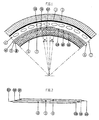
- Fig. 1 shows a section of the laminate in place in a passage
- Fig. 2 shows the construction of a fabric being a part of the laminate.
- the embodiment of the lining laminate according to the invention comprises a fabric 6 which is made of continuos glass fibres and which on its side turned to the inner film 5 carries cut fibres 7, preferably cut glass fibres, forming a combination fabric.
- the cut fibres can constitute a mat which is laid on the fabric 6.
- the material of the plaited reinforcement 4 is composed of roving and the roving can be of "KOSMOS", conventional or bulked type.
- the glass fibre, being a part of the combination fabric, i.e. the fabric 6 together with the cut glass fibres 7 put in it, can be composed of E-, ECR-, ADVANTEX-, C-glass or of other fibre materials of high quality.
- the fabric 6 with cut glass fibres 7, denoted combination fabric has among other things that quality that it absorbs resin to an essentially larger extent than the reinforcement 4 and due to that fact the resin, being part of the laminate 1, will in first hand be absorbed by the combination fabric 6, 7 until this one is saturated and thanks to that fact a concentration of resin to the inner surface portion or surface layer of the laminate is obtained.
- an internal surface layer comprising solely resin with cut glass fibres as a reinforcement is obtained, which layer is resistant to corrosion.
- the cured resin intimately connects the combination fabric 7 with adjacent reinforcement layer 4 so that a lining with a very high strength is created.
- the fabric 6, being part of the laminate, has a joint which extends in axial direction and comprises according to this embodiment three layers 8-10, put together.
- the three layers have in the starting-point displaced positions in relation to each other, which is shown in fig. 2.
- three layers 8-10 which are essentially of the same size, and which have been put on top of each other but are laterally displaced.
- the displacement is made in that way that the axial side portion B of the layer 8 has been pulled out outside the axial side portion B of the layer 8, the axial side portion B of which has been pulled out outside the axial side portion B of the layer 10.
- the described joint arrangement makes possible that the end portions of the different layers can slide in relation to each other during the installation/expansion phase. This fact makes the new laminate very flexible and adaptable, seen from a diametric point of view.
- the joint arrangement is designed in that way that the distances a 1 and a 2 (sec Fig. 1), which in the normal case are essentially of the same size, always are larger than the stretching out of the fabric 6, which means that the joint 9A/10B is landed inside the end portion 10A of the layer 10, whereas the joint 8A/9B is landed inside of the other end portion 8B of the layer 8. This fact means that the mentioned joints are protected by the end portions 10A and 8B, which leads to an extremely good strength of the laminate.
Abstract
Description
Claims (2)
- A laminate with a ring-Shaped cross-section for lining a passage, entirely or partially surrounded by walls, on or under the ground, for instance pipe lines for gas, water and/or a sewerage, channels for instance for ventilation, smoke and the like, comprising at least one layer of a reinforcement of continuous fibres, a curable resin and a plastic foil or a plastic film, which is on the inside of the laminate when this one is introduced into the passage that shall be lined, there being arranged a fabric of fibres between the inner film and the reinforcement, which fabric on its side turned to the inner film carries cut fibres, and which together with its cut fibres form a combination fabric, which can absorb resin and concentrate the curable resin at the inner surface of the cured laminate, characterized in that the fabric (6) comprises at least two layers (8-10), put together, each one of which in an inactive position having two essentially parallel side portions (A, B), and which are displaced in relation to each other in such a way that in an active position, i.e. when the side portions (A, B) have been laid to form a ring, there is formed a joint between the one side portion (A) of the one layer (8, 9) and the other end portion (B), of the other layer (9, 10), the remaining end portions (B, A) of the two layers (8, 9; 9, 10) being positioned in that way that they cover the joint on each side, and the joint arrangement making it possible for the end portions of the layers to be able to slide in relation to each other during the installation/expansion phase.
- A laminate according to claim 1, the fabric comprising three layers (8-10), put together, and the layer (8) being positioned on top and the layer (10) at the bottom at the starting point, characterized in that the first end portion (9A) of the intermediate layer forms, radially seen, an outer joint with the second end portion (10B) of the lowermost layer, that the first end portion (8B) of the uppermost layer forms, radially seen, an inner joint with the second end portion (9B) of the intermediate layer, and that the first end portion (10A) of the lowermost layer and the second end portion (8B) of the uppermost layer cover the mentioned joints (9A/10B) and (8A/9B) in such a way that even if the end portions of the layers slide in relation to each other at respective joint, the joints (9A/10B) and (8A/9B) will be covered by the mentioned end portions (10A, 8B).
Applications Claiming Priority (3)
| Application Number | Priority Date | Filing Date | Title |
|---|---|---|---|
| SE9801504 | 1998-04-29 | ||
| SE9801504A SE9801504L (en) | 1998-04-29 | 1998-04-29 | Laminates for lining pipelines |
| PCT/SE1999/000684 WO1999058326A1 (en) | 1998-04-29 | 1999-04-27 | Laminate |
Publications (2)
| Publication Number | Publication Date |
|---|---|
| EP1082210A1 EP1082210A1 (en) | 2001-03-14 |
| EP1082210B1 true EP1082210B1 (en) | 2004-08-11 |
Family
ID=20411132
Family Applications (1)
| Application Number | Title | Priority Date | Filing Date |
|---|---|---|---|
| EP99927019A Expired - Lifetime EP1082210B1 (en) | 1998-04-29 | 1999-04-27 | Laminate |
Country Status (8)
| Country | Link |
|---|---|
| EP (1) | EP1082210B1 (en) |
| JP (1) | JP2002514529A (en) |
| AT (1) | ATE273125T1 (en) |
| AU (1) | AU4401899A (en) |
| DE (1) | DE69919352D1 (en) |
| ES (1) | ES2226397T3 (en) |
| SE (1) | SE9801504L (en) |
| WO (1) | WO1999058326A1 (en) |
Cited By (1)
| Publication number | Priority date | Publication date | Assignee | Title |
|---|---|---|---|---|
| GB2606888B (en) * | 2018-10-16 | 2023-07-19 | Sanexen Services Environnementaux Inc | Liners for lining a conduit to transport a fluid |
Families Citing this family (2)
| Publication number | Priority date | Publication date | Assignee | Title |
|---|---|---|---|---|
| CA3088019A1 (en) | 2018-10-16 | 2020-04-23 | Sanexen Services Environnementaux Inc. | Systems and methods for rehabilitation of water conduits and other conduits |
| CN112677576B (en) * | 2020-11-30 | 2023-10-20 | 安徽工程大学 | Breathable clothing functional cloth |
Family Cites Families (5)
| Publication number | Priority date | Publication date | Assignee | Title |
|---|---|---|---|---|
| EP0087613B1 (en) * | 1982-02-26 | 1986-05-14 | Hüls Troisdorf Aktiengesellschaft | Method and device for the production of multi-layer insulating tubes of foamed plastic strips |
| SE9100525D0 (en) * | 1991-02-22 | 1991-02-22 | Inpipe Sweden Ab | LAMINATE |
| DK0795715T3 (en) * | 1991-12-04 | 2000-10-16 | Ashimori Ind Co Ltd | Method and material for lining before |
| FR2714448B1 (en) * | 1993-12-24 | 1996-01-26 | Chomarat & Cie | Reinforcement element usable in particular for the repair of pipes. |
| US5836357A (en) * | 1995-10-26 | 1998-11-17 | Bay Mills Ltd. | Pressure-expandable conduit liner |
-
1998
- 1998-04-29 SE SE9801504A patent/SE9801504L/en not_active IP Right Cessation
-
1999
- 1999-04-27 AT AT99927019T patent/ATE273125T1/en not_active IP Right Cessation
- 1999-04-27 JP JP2000548152A patent/JP2002514529A/en active Pending
- 1999-04-27 AU AU44018/99A patent/AU4401899A/en not_active Abandoned
- 1999-04-27 ES ES99927019T patent/ES2226397T3/en not_active Expired - Lifetime
- 1999-04-27 WO PCT/SE1999/000684 patent/WO1999058326A1/en active IP Right Grant
- 1999-04-27 EP EP99927019A patent/EP1082210B1/en not_active Expired - Lifetime
- 1999-04-27 DE DE69919352T patent/DE69919352D1/en not_active Expired - Lifetime
Cited By (1)
| Publication number | Priority date | Publication date | Assignee | Title |
|---|---|---|---|---|
| GB2606888B (en) * | 2018-10-16 | 2023-07-19 | Sanexen Services Environnementaux Inc | Liners for lining a conduit to transport a fluid |
Also Published As
| Publication number | Publication date |
|---|---|
| EP1082210A1 (en) | 2001-03-14 |
| ES2226397T3 (en) | 2005-03-16 |
| SE9801504D0 (en) | 1998-04-29 |
| SE510939C2 (en) | 1999-07-12 |
| DE69919352D1 (en) | 2004-09-16 |
| ATE273125T1 (en) | 2004-08-15 |
| SE9801504L (en) | 1999-07-12 |
| WO1999058326A1 (en) | 1999-11-18 |
| AU4401899A (en) | 1999-11-29 |
| JP2002514529A (en) | 2002-05-21 |
Similar Documents
| Publication | Publication Date | Title |
|---|---|---|
| EP0646060B1 (en) | Laminate | |
| US6923217B2 (en) | Fiber reinforced composite liner for lining an existing conduit and method of manufacture | |
| US6932116B2 (en) | Fiber reinforced composite liner for lining an existing conduit and method of manufacture | |
| US6196271B1 (en) | Liner hose for reconstruction of conduits and pipelines and a method for manufacture thereof | |
| KR880000383Y1 (en) | Underground piping | |
| KR100917943B1 (en) | Plastic hollow body, in particular plastic pipe | |
| CA2514890A1 (en) | Lining material for pipelines | |
| ATE283443T1 (en) | LINING HOSE WITH A FLEECE LAYER LAMINATED ONTO A FOIL HOSE | |
| JP2005507331A5 (en) | ||
| US11867343B2 (en) | Coated pipe and pipe combination | |
| EP1082210B1 (en) | Laminate | |
| JP2006194430A (en) | Pressure hose | |
| US9945504B2 (en) | Lining element for the rehabilitation of a pipeline | |
| US5030489A (en) | Plastic molding for pipe systems | |
| JP2011143684A (en) | Lining material | |
| US20220105700A1 (en) | Pipe liner | |
| PL242591B1 (en) | Layer of fibres, preferably a layer with non-unidirectional arrangement of fibres, for production of a sleeve for renovation of channels, multi-layered sheet, preferably for production of a sleeve for renovation of channels, and the layered sleeve for renovation of channels | |
| RU178927U1 (en) | POLYMER HOSE FOR PIPELINE | |
| RU2211397C2 (en) | Pipe line | |
| ITRE980092A1 (en) | INTERNAL COATING FOR PIPES AND / OR CONDUCTED IN PRESSURE. | |
| JP2001030225A (en) | Refractory double layer pipe |
Legal Events
| Date | Code | Title | Description |
|---|---|---|---|
| PUAI | Public reference made under article 153(3) epc to a published international application that has entered the european phase |
Free format text: ORIGINAL CODE: 0009012 |
|
| 17P | Request for examination filed |
Effective date: 20001019 |
|
| AK | Designated contracting states |
Kind code of ref document: A1 Designated state(s): AT BE CH DE DK ES FI FR GB IE IT LI NL SE |
|
| GRAP | Despatch of communication of intention to grant a patent |
Free format text: ORIGINAL CODE: EPIDOSNIGR1 |
|
| GRAS | Grant fee paid |
Free format text: ORIGINAL CODE: EPIDOSNIGR3 |
|
| GRAA | (expected) grant |
Free format text: ORIGINAL CODE: 0009210 |
|
| AK | Designated contracting states |
Kind code of ref document: B1 Designated state(s): AT BE CH DE DK ES FI FR GB IE IT LI NL SE |
|
| PG25 | Lapsed in a contracting state [announced via postgrant information from national office to epo] |
Ref country code: NL Free format text: LAPSE BECAUSE OF FAILURE TO SUBMIT A TRANSLATION OF THE DESCRIPTION OR TO PAY THE FEE WITHIN THE PRESCRIBED TIME-LIMIT Effective date: 20040811 Ref country code: LI Free format text: LAPSE BECAUSE OF FAILURE TO SUBMIT A TRANSLATION OF THE DESCRIPTION OR TO PAY THE FEE WITHIN THE PRESCRIBED TIME-LIMIT Effective date: 20040811 Ref country code: IT Free format text: LAPSE BECAUSE OF FAILURE TO SUBMIT A TRANSLATION OF THE DESCRIPTION OR TO PAY THE FEE WITHIN THE PRESCRIBED TIME-LIMIT;WARNING: LAPSES OF ITALIAN PATENTS WITH EFFECTIVE DATE BEFORE 2007 MAY HAVE OCCURRED AT ANY TIME BEFORE 2007. THE CORRECT EFFECTIVE DATE MAY BE DIFFERENT FROM THE ONE RECORDED. Effective date: 20040811 Ref country code: FR Free format text: LAPSE BECAUSE OF FAILURE TO SUBMIT A TRANSLATION OF THE DESCRIPTION OR TO PAY THE FEE WITHIN THE PRESCRIBED TIME-LIMIT Effective date: 20040811 Ref country code: FI Free format text: LAPSE BECAUSE OF FAILURE TO SUBMIT A TRANSLATION OF THE DESCRIPTION OR TO PAY THE FEE WITHIN THE PRESCRIBED TIME-LIMIT Effective date: 20040811 Ref country code: CH Free format text: LAPSE BECAUSE OF FAILURE TO SUBMIT A TRANSLATION OF THE DESCRIPTION OR TO PAY THE FEE WITHIN THE PRESCRIBED TIME-LIMIT Effective date: 20040811 Ref country code: BE Free format text: LAPSE BECAUSE OF FAILURE TO SUBMIT A TRANSLATION OF THE DESCRIPTION OR TO PAY THE FEE WITHIN THE PRESCRIBED TIME-LIMIT Effective date: 20040811 Ref country code: AT Free format text: LAPSE BECAUSE OF FAILURE TO SUBMIT A TRANSLATION OF THE DESCRIPTION OR TO PAY THE FEE WITHIN THE PRESCRIBED TIME-LIMIT Effective date: 20040811 |
|
| REG | Reference to a national code |
Ref country code: GB Ref legal event code: FG4D |
|
| REG | Reference to a national code |
Ref country code: CH Ref legal event code: EP |
|
| REG | Reference to a national code |
Ref country code: IE Ref legal event code: FG4D |
|
| REF | Corresponds to: |
Ref document number: 69919352 Country of ref document: DE Date of ref document: 20040916 Kind code of ref document: P |
|
| PG25 | Lapsed in a contracting state [announced via postgrant information from national office to epo] |
Ref country code: SE Free format text: LAPSE BECAUSE OF FAILURE TO SUBMIT A TRANSLATION OF THE DESCRIPTION OR TO PAY THE FEE WITHIN THE PRESCRIBED TIME-LIMIT Effective date: 20041111 Ref country code: DK Free format text: LAPSE BECAUSE OF FAILURE TO SUBMIT A TRANSLATION OF THE DESCRIPTION OR TO PAY THE FEE WITHIN THE PRESCRIBED TIME-LIMIT Effective date: 20041111 |
|
| PG25 | Lapsed in a contracting state [announced via postgrant information from national office to epo] |
Ref country code: DE Free format text: LAPSE BECAUSE OF FAILURE TO SUBMIT A TRANSLATION OF THE DESCRIPTION OR TO PAY THE FEE WITHIN THE PRESCRIBED TIME-LIMIT Effective date: 20041112 |
|
| NLV1 | Nl: lapsed or annulled due to failure to fulfill the requirements of art. 29p and 29m of the patents act | ||
| REG | Reference to a national code |
Ref country code: CH Ref legal event code: PL |
|
| REG | Reference to a national code |
Ref country code: ES Ref legal event code: FG2A Ref document number: 2226397 Country of ref document: ES Kind code of ref document: T3 |
|
| PG25 | Lapsed in a contracting state [announced via postgrant information from national office to epo] |
Ref country code: IE Free format text: LAPSE BECAUSE OF NON-PAYMENT OF DUE FEES Effective date: 20050427 Ref country code: GB Free format text: LAPSE BECAUSE OF NON-PAYMENT OF DUE FEES Effective date: 20050427 |
|
| PLBE | No opposition filed within time limit |
Free format text: ORIGINAL CODE: 0009261 |
|
| STAA | Information on the status of an ep patent application or granted ep patent |
Free format text: STATUS: NO OPPOSITION FILED WITHIN TIME LIMIT |
|
| 26N | No opposition filed |
Effective date: 20050512 |
|
| EN | Fr: translation not filed | ||
| EN | Fr: translation not filed | ||
| PGFP | Annual fee paid to national office [announced via postgrant information from national office to epo] |
Ref country code: ES Payment date: 20051130 Year of fee payment: 7 |
|
| GBPC | Gb: european patent ceased through non-payment of renewal fee |
Effective date: 20050427 |
|
| PG25 | Lapsed in a contracting state [announced via postgrant information from national office to epo] |
Ref country code: ES Free format text: LAPSE BECAUSE OF NON-PAYMENT OF DUE FEES Effective date: 20060428 |
|
| REG | Reference to a national code |
Ref country code: ES Ref legal event code: FD2A Effective date: 20060428 |