EP1081924A2 - Single-ended subscriber loop qualification for xDSL service - Google Patents
Single-ended subscriber loop qualification for xDSL service Download PDFInfo
- Publication number
- EP1081924A2 EP1081924A2 EP00307432A EP00307432A EP1081924A2 EP 1081924 A2 EP1081924 A2 EP 1081924A2 EP 00307432 A EP00307432 A EP 00307432A EP 00307432 A EP00307432 A EP 00307432A EP 1081924 A2 EP1081924 A2 EP 1081924A2
- Authority
- EP
- European Patent Office
- Prior art keywords
- subscriber loop
- loop
- subscriber
- xdsl
- electrical characteristics
- Prior art date
- Legal status (The legal status is an assumption and is not a legal conclusion. Google has not performed a legal analysis and makes no representation as to the accuracy of the status listed.)
- Withdrawn
Links
- 238000012797 qualification Methods 0.000 title abstract description 22
- 238000000034 method Methods 0.000 claims abstract description 75
- 238000012360 testing method Methods 0.000 claims abstract description 34
- 230000005540 biological transmission Effects 0.000 claims description 16
- 238000009434 installation Methods 0.000 claims description 10
- 238000009413 insulation Methods 0.000 claims description 9
- 238000004364 calculation method Methods 0.000 claims description 8
- 239000004020 conductor Substances 0.000 claims description 8
- 239000004606 Fillers/Extenders Substances 0.000 claims description 7
- 239000000969 carrier Substances 0.000 claims description 4
- 239000000523 sample Substances 0.000 claims description 4
- 238000004891 communication Methods 0.000 claims description 3
- 238000004590 computer program Methods 0.000 claims description 3
- 230000006698 induction Effects 0.000 claims description 2
- 230000003472 neutralizing effect Effects 0.000 claims description 2
- 238000001514 detection method Methods 0.000 claims 1
- 230000004044 response Effects 0.000 abstract description 2
- 238000012216 screening Methods 0.000 abstract 1
- 238000010586 diagram Methods 0.000 description 12
- 230000008569 process Effects 0.000 description 9
- 238000005516 engineering process Methods 0.000 description 6
- 238000005259 measurement Methods 0.000 description 5
- 230000000704 physical effect Effects 0.000 description 3
- RYGMFSIKBFXOCR-UHFFFAOYSA-N Copper Chemical compound [Cu] RYGMFSIKBFXOCR-UHFFFAOYSA-N 0.000 description 2
- 230000003213 activating effect Effects 0.000 description 1
- 230000003044 adaptive effect Effects 0.000 description 1
- 238000004422 calculation algorithm Methods 0.000 description 1
- 229910052802 copper Inorganic materials 0.000 description 1
- 239000010949 copper Substances 0.000 description 1
- 230000001934 delay Effects 0.000 description 1
- 238000011161 development Methods 0.000 description 1
- 238000011156 evaluation Methods 0.000 description 1
- 239000012212 insulator Substances 0.000 description 1
- 239000011159 matrix material Substances 0.000 description 1
- 230000009467 reduction Effects 0.000 description 1
- 230000008054 signal transmission Effects 0.000 description 1
- 238000004088 simulation Methods 0.000 description 1
Images


Classifications
-
- H—ELECTRICITY
- H04—ELECTRIC COMMUNICATION TECHNIQUE
- H04M—TELEPHONIC COMMUNICATION
- H04M3/00—Automatic or semi-automatic exchanges
- H04M3/22—Arrangements for supervision, monitoring or testing
- H04M3/26—Arrangements for supervision, monitoring or testing with means for applying test signals or for measuring
- H04M3/28—Automatic routine testing ; Fault testing; Installation testing; Test methods, test equipment or test arrangements therefor
- H04M3/30—Automatic routine testing ; Fault testing; Installation testing; Test methods, test equipment or test arrangements therefor for subscriber's lines, for the local loop
- H04M3/305—Automatic routine testing ; Fault testing; Installation testing; Test methods, test equipment or test arrangements therefor for subscriber's lines, for the local loop testing of physical copper line parameters, e.g. capacitance or resistance
- H04M3/306—Automatic routine testing ; Fault testing; Installation testing; Test methods, test equipment or test arrangements therefor for subscriber's lines, for the local loop testing of physical copper line parameters, e.g. capacitance or resistance for frequencies above the voice frequency, e.g. xDSL line qualification
-
- H—ELECTRICITY
- H04—ELECTRIC COMMUNICATION TECHNIQUE
- H04B—TRANSMISSION
- H04B3/00—Line transmission systems
- H04B3/02—Details
- H04B3/46—Monitoring; Testing
-
- H—ELECTRICITY
- H04—ELECTRIC COMMUNICATION TECHNIQUE
- H04M—TELEPHONIC COMMUNICATION
- H04M3/00—Automatic or semi-automatic exchanges
- H04M3/22—Arrangements for supervision, monitoring or testing
- H04M3/26—Arrangements for supervision, monitoring or testing with means for applying test signals or for measuring
- H04M3/28—Automatic routine testing ; Fault testing; Installation testing; Test methods, test equipment or test arrangements therefor
- H04M3/30—Automatic routine testing ; Fault testing; Installation testing; Test methods, test equipment or test arrangements therefor for subscriber's lines, for the local loop
-
- H—ELECTRICITY
- H04—ELECTRIC COMMUNICATION TECHNIQUE
- H04M—TELEPHONIC COMMUNICATION
- H04M3/00—Automatic or semi-automatic exchanges
- H04M3/005—Interface circuits for subscriber lines
-
- H—ELECTRICITY
- H04—ELECTRIC COMMUNICATION TECHNIQUE
- H04M—TELEPHONIC COMMUNICATION
- H04M3/00—Automatic or semi-automatic exchanges
- H04M3/22—Arrangements for supervision, monitoring or testing
- H04M3/26—Arrangements for supervision, monitoring or testing with means for applying test signals or for measuring
- H04M3/28—Automatic routine testing ; Fault testing; Installation testing; Test methods, test equipment or test arrangements therefor
- H04M3/30—Automatic routine testing ; Fault testing; Installation testing; Test methods, test equipment or test arrangements therefor for subscriber's lines, for the local loop
- H04M3/305—Automatic routine testing ; Fault testing; Installation testing; Test methods, test equipment or test arrangements therefor for subscriber's lines, for the local loop testing of physical copper line parameters, e.g. capacitance or resistance
Definitions
- the invention relates generally to the provision of data services over subscriber loops in the Public Switched Telephone Network and, in particular, to a method and apparatus for the single ended qualification of subscriber loops to determine the suitability of such loops for the provision of high-speed data services.
- DSL Digital Subscriber Line
- ADSL Asymmetrical Digital Subscriber Line
- HDSL High-bit-rate Digital Subscriber Line
- RDSL Rate Adaptive Digital Subscriber Line
- SDSL Symmetric Digital Subscriber Line
- VDSL Very High-speed Digital Subscriber Line
- a problem encountered in the provision of xDSL services is that the subscriber loops have been largely neglected from a technology upgrade perspective.
- Existing subscriber loops were designed for voice telephony as opposed to high-speed data services. Consequently, many subscriber loops include wire gage changes and bridged taps (unused extension lines) which limit the available bandwidth.
- Other equipment installed on subscriber loops may also render the loop unsuitable for the provision of xDSL service. For example, load coils, voice frequency repeaters, loop extenders, Private Branch Exchanges (PBXs), line intercepts and incompatible data services all render subscriber loops unsuitable for the provision of xDSL service.
- PBXs Private Branch Exchanges
- TDR Time Domain Reflectrometry
- an aspect of the invention provides a method of qualifying a subscriber loop for xDSL services.
- the subscriber loop is connected to a public switched telephone network (PSTN) via a switch at a central office (CO).
- PSTN public switched telephone network
- CO central office
- the method comprises the steps of: determining, from a CO end of the subscriber loop, one or more electrical characteristics of the subscriber loop; and estimating, based on the determined electrical characteristics, an xDSL bandwidth available on the subscriber loop.
- a further aspect of the present invention provides a system for qualifying a subscriber loop for xDSL services.
- the subscriber loop is connected to a public switched telephone network (PSTN) via a switch at a central office (CO).
- PSTN public switched telephone network
- CO central office
- the system comprises a processor adapted to determine, from a CO end of the subscriber loop, one or more electrical characteristics of the subscriber loop, and to estimate an xDSL bandwidth of the subscriber loop based on the determined electrical characteristics.
- the present invention provides a method and apparatus for single ended qualification of subscriber loops for xDSL services.
- Electrical characteristics of the subscriber loop preferably include values for: resistance (R); capacitance (C); inductance (L); and conductance (G) for each cable segment forming the subscriber loop.
- Additional electrical characteristics can, for example, include a wide band noise (WBN) value on the subscriber loop, and the presence of any one or more of: bridged taps; load coils; loop extenders; and other devices in the subscriber loop.
- WBN wide band noise
- the electrical characteristics of the subscriber loop can be determined by any one or more of; probing the subscriber loop from the CO end; estimation based on physical characteristics of the subscriber loop, and use of default values.
- values of R, L, G, and C are contained in a cable properties database and may be accessed on the basis of the physical characteristics of the subscriber loop.
- the physical characteristics of the subscriber loop preferably include information of: length; conductor size; cable insulation type; and cable installation type of each cable segment forming the subscriber loop, as well as information of devices installed on the subscriber loop. These physical characteristics of the subscriber loop are preferably obtained from database queries, but at least some physical characteristics can be estimated from measured electrical properties of the subscriber loop, and/or approximated using default values.
- a carrier service database includes information of physical characteristics of the subscriber loop as well as devices and services installed on the subscriber loop.
- a subscriber loop record containing information specific to the loop is extracted from the data base and screened for devices and services known to be incompatible with xDSL services. If any such incompatible devices or services are found, the loop is disqualified. On the other hand, if no incompatible devices or services are found, the electrical characteristics of the subscriber loop are used to calculate estimates of the up-stream and down-stream bit-rates (band-width) of wide-band xDSL signals transmitted over the subscriber loop.
- the subscriber loop prior to band-width estimation, is probed to detect the presence of any one or more of metallic faults, load coils, or line intercepts. If any of these conditions are detected, the subscriber loop is disqualified.
- the present invention therefore provides a method and apparatus to permit the single ended qualification of subscriber loops, and thus a service provider benefits from a reduction in the skill level required by operators/technicians performing the qualification.
- the method and apparatus of the preferred embodiments therefore enable the pre-qualification of subscriber loops to permit a service provider to inform any service subscriber of the qualification of their subscriber loop on request.
- the present invention provides a simple and economical method and apparatus for the single ended qualification of subscriber loops for xDSL service.
- the invention provides a method and apparatus for the single ended qualification of copper wire subscriber loops in a switched telephone network.
- FIG. 1 is a schematic diagram showing a central office (CO) 110 in a switched telephone network connected to a plurality of voice-grade subscriber loops.
- a processor 100 may access the CO 110, and various test equipment for qualifying subscriber loops. Access may be accomplished, for example, via a wide area network (WAN) 102 to which the processor 100 is connected by a data link 104.
- WAN wide area network
- Processor 100 executes an algorithm for subscriber loop qualification to determine the suitability of the subscriber loops for xDSL services.
- a carrier service database 106 is connected to the WAN by a link 108.
- the carrier service database 106 which may either be located at the switch or (preferably) on a server attached to the WAN, contains subscriber equipment records indexed by subscriber directory numbers, for example.
- the carrier service database may include the physical characteristics of the subscriber loops, such as loop length, wire gauge, bridge taps, etc. Also, addressable on the local area network are other central offices (not shown) providing telephone services to other subscribers.
- Telephone services are provided to a subscriber 114 via a subscriber loop divided in two segments 116 and 118.
- This particular subscriber loop includes a load coil 120 installed between segments 116 and 118. Load coils are the used to improve transmission of signals in the voice frequency band.
- Telephone services are provided to subscriber 122 via a subscriber loop comprising two segments 124 and 126. Installed between subscriber loop segment 124 and subscriber loop segment 126 is a voice frequency repeater 128. Voice frequency repeaters are used to amplify and retransmit signals in the voice frequency band. Telephone services are provided to subscriber 130 via a subscriber loop divided into two segments 132 and 134. Installed between loop segments 132 and 134 is a loop extender 136. Loop extenders are used to amplify signals in the voice frequency band. Telephone services are provided to subscribers 138 and 140 connected to a key system 142 via subscriber loop 144. Subscribers 138 and 140 are connected to the key system 142 via links 146 and 148.
- Intercepted telephone services are provided to subscriber 150 via subscriber loop 152.
- Installed on subscriber loop 152 is a recording system 154 which records all the voice frequency payload carried by the subscriber loop 152.
- Integrated Services Digital Network (ISDN) services are provided to subscriber 156 over subscriber loop 158.
- Plain Old Telephone Service (POTS) voice-grade telephone service is provided to a subscriber 160 by a single segment subscriber loop 162.
- POTS Plain Old Telephone Service
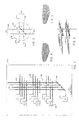
- FIG. 2 is a schematic diagram showing a portion of the public switch 110 which serves subscriber loop 200 terminated on line card 202.
- Test equipment 204 can be connected to individual subscriber loops through an access grid 206 which consists of an hierarchy of buses 208 and 210.
- Subscriber loop 200 can be respectively connected to the access grid 206 by electrically activating a connection point 212. This permits the probing of individual subscriber loops to determine electrical characteristics of each loop.
- FIG. 3 shows the details of the connection point 212.
- Each line card 202 provides a tip and ring pair of conductors 214 and 216.
- tip and ring pairs 214 and 216 are connected to the tip and ring pairs 218 and 220 of the subscriber loop 200.
- This connection is provided at the connection point by relays 222.
- the tip and ring pair 218 and 220 of subscriber loop 200 is connected to an associated tip and ring pair 224 and 226 of a bus 210 in the access grid 206. This interconnection permits the test equipment 204 to be connected directly to the subscriber loop 200.
- FIGs. 4, 5 and 6 illustrate different methods used to install cables carrying subscriber loops between the central office and subscriber premises. These methods of installation comprise: buried cable shown in FIG. 4 in which the cable is simply laid in a trench and carried with earth.; underground cable shown in FIG. 5 in which the cable is run through a conduit buried in the earth; and, aerial cable shown in FIG. 6 in which the cable is supported by poles above the ground. Each type of installation requires cable with particular properties.
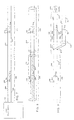
- FIG. 7 is a schematic diagram showing the deployment of a subscriber loop 200 connected to a public switch 110.
- Subscriber loop 200 is made up of two segments.
- a first segment 300 includes a tip and ring pair 302 and 304 of a first wire gauge. This first segment 300 is characterized by having a resistance 306 and an electrical capacitance 308.
- the second segment 310 is made up of tip and ring pairs 312 and 314 of a second gauge. This second segment is characterized by an electrical resistance 316 and an electrical capacitance 318.
- FIG. 8 shows another type of subscriber loop deployment in which the tip and ring pairs are shielded.
- Subscriber loops segment 320 is shielded by an outer sheath filled with a dielectric insulator 324. This segment is characterized by an electrical resistance 326 and an electrical capacitance 328.
- Subscriber loop segment 330 is shielded by a sheath 332 that is air filled. This segment is characterized by an electrical resistance 336 and an electrical capacitance 338.
- FIG. 9 shows a subscriber loop connected to a telephone 374, the subscriber loop includes a bridged tap 360.
- subscriber loop segment 340 includes a tip and ring pair 342 and 344 having an electrical resistance 346 and an electrical capacitance 348.
- Loop segment 350 includes a tip and ring pair 352 and 354 having an electrical resistance 356 and an electrical capacitance 358.
- a bridged tap segment 360 includes a tip and ring pair 362 and 364 having an electrical resistance 366 and an electrical capacitance 368, The bridged top segment 360 is connected to the loop segment 350 at connection points 370 and 372.
- subscriber loops can be qualified for xDSL services on an individual basis, or in groups.
- an individual subscriber loop could be qualified in response to a request for service by the subscriber.
- a carrier service provider can elect to qualify a group of subscriber loops (e.g. all of the subscriber loops connected to a particular switch) at a time convenient to the carrier service provider, such as, for example, following an upgrade of a switch to enable DSL services to be provided by the switch.
- FIG. 10 illustrates a process for qualifying a group of subscriber loops, it being understood that the same process also applies when only a single subscriber loop is to be qualified.
- the processor 100 (FIG. 1) is instructed to qualify one or more loops in a start 400.
- the processor 100 determines whether a last subscriber loop identified in a qualification request list has been qualified. If at least one subscriber loop remains to be qualified, the processor 100 queries the carrier service provider database 106, and retrieves a subscriber loop record located using the subscriber directory number, for example.
- the subscriber loop record contains information respecting the physical characteristics of the subscriber loop and services deployed on the loop. As described above, the information regarding physical characteristics preferably includes the identity (type) of equipment installed for the subscriber loop.
- the information also preferably provides data describing the make-up of the loop including a length, gauge size, insulation type and installation type for each cable segment (see FIGs. 7-9) forming the subscriber loop.
- the processor 100 screens the customer record to identify any equipment or services on the subscriber loop that are incompatible with xDSL (typically because they are known to reduce the available bandwidth above voice frequency to zero, or a negligible margin).
- Incompatible equipment and services include voice frequency (VF) repeaters, line intercepts, loop extenders, induction neutralizing transformers, added main line (AML) carriers, bridge lifters, and private branch exchange (PBX) services.
- FIG. 1 illustrates exemplary subscriber loops equipped with devices and services which preclude the provision of xDSL services.
- the processor 100 disqualifies the subscriber loop for xDSL services at step 411. Disqualification means that xDSL services cannot be deployed on the subscriber loop until (or unless) the incompatible equipment and/or services are removed. Following disqualification of the subscriber loop, the processor 100 records the disqualification in the subscriber loop record, or one qualification report, or both. The processor selects a next subscriber loop at step 402, and restarts the qualification process.
- the processor 100 determines (step 412) whether test equipment is available (either co-located with the switch or elsewhere on the network), that is capable of probing the subscriber line to enable discovery of the physical make-up of the subscriber loop.
- test equipment is not available (step 412)
- the processor ends evaluation of the subscriber loop, because it lacks sufficient information to estimate available bandwidth. In this case, the processor 100 selects a new subscriber loop at step 402, and restarts the qualification process. If test equipment is determined to be available (at step 412), then the processor proceeds to discovery of the physical characteristics of the subscriber loop (step 414).
- the subscriber loop can be probed using test signals to detect the presence of shorts, opens, grounds and load coils, as taught by United States Patent No. 4,870,675 (Fuller et al.).
- the methods described by Fuller can be adapted to detect any of a variety of devices which have a detectable signature, such as, for example, line intercepts, and added main line (AML) carriers.
- Test equipment is also known for probing subscriber loops (through the switch), to measure values of, for example, AC and DC voltages, resistance and capacitance over the entire subscriber loop.
- test equipment to the subscriber loop independently of the switch (i.e. on the analogue side of the loop) using a suitable loop test equipment, such as, for example, TelaccordTM manufactured by Tollgrade Communications, Inc.
- a suitable loop test equipment such as, for example, TelaccordTM manufactured by Tollgrade Communications, Inc.
- TelaccordTM manufactured by Tollgrade Communications, Inc.
- This equipment which is illustrated in FIG. 2, permits measurement of wide-band noise on the subscriber loop, in addition to other electrical characteristics. Wide band noise on the subscriber loop cannot be measured through the switch. Accordingly, if test equipment capable of measuring wide band noise is not available, a default value (e.g. -140 dBm/Hz) can be used to compute a Signal to Noise Ratio (SNR), as will be explained below in more detail.
- SNR Signal to Noise Ratio
- Some communication devices e.g. modems
- Some communication devices available on the market generate high levels of noise in the wide-band region.
- Such devices are installed on the subscriber loop (i.e. at the customer premises), it is possible that a measured value of wide band noise will be significantly higher than the default value. In such cases, it is preferable to adjust the default value of the wide band noise to a higher value.
- the subscriber loop record will not contain information of metallic faults or load coils. Accordingly, at step 416, the processor controls the test equipment to probe the subscriber loop to test for metallic faults (e.g. shorts or grounds), line intercepts, and load coils (as well as any other devices which preclude transmission of wide-band xDSL signals). If any such conditions are found, the processor disqualifies the subscriber loop (step 411) because the subscriber loop cannot support xDSL services until these conditions are resolved. Otherwise, the processor completes the discovery of the physical characteristics of the subscriber loop, and prepares for band-width estimation (step 418).
- metallic faults e.g. shorts or grounds
- line intercepts e.g. line intercepts
- load coils e.g. shorts or grounds
- the processor Upon completion of discovery of the physical characteristics of the subscriber loop (steps 414 - 416), the processor preferably updates the customer record with the discovered characteristics, and then proceeds with bandwidth estimation (step 418).
- the processor 100 estimates the total bandwidth available for wide-band xDSL signals transmitted over the subscriber loop.
- the total bandwidth is simply a total bit-rate at which data can be transmitted in each direction (e.g. up-stream and down-stream) over the subscriber loop.
- the up-stream and down-stream bandwidths may be similar, in which case it may be possible to qualify the subscriber loop by calculation of bandwidth in only one direction.
- up-stream and down-stream bandwidths typically differ significantly, and it is normally preferable to estimate values for both the up-stream and downstream bandwidths.
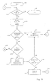
- FIG. 11 illustrates in greater detail the process of estimating bandwidth (step 418 of FIG. 10) in accordance with the present invention.
- the band width (or bit-rate of data transmission) available on a subscriber loop (or any portion thereof) at a particular frequency can be calculated from the signal-to-noise ratio (SNR) of the subscriber loop at that frequency.
- SNR signal-to-noise ratio
- the SNR at a particular frequency can, in turn, be calculated from values of resistance (R), inductance (L), conductance (G) and capacitance (C) of the loop.
- R, L, G, and C are primarily functions of physical properties of the cable (e.g. conductor gauge (size), insulation type, and temperature) and may also vary with frequency.
- the wide-band xDSL signal is considered to be divided into a plurality of subchannels (e.g. of 4312 Hz width), with each subchannel having a predetermined center-frequency.
- the subscriber loop is considered to be divided into one or more cable segments having a respective combination of length, conductor gauge, insulation type, and installation type. This permits values of R, L, G, and C to be found for each cable segment, which can be aggregated to calculate a SNR for each sub-channel.
- the SNR for each sub-channel is then used to determine a bit-rate (bandwidth) for each subchannel.
- the subchannel bit-rates are then summed to find the total bandwidth available for wide-band xDSL signal over the subscriber loop.
- the processor 100 selects a subchannel having a center frequency (f), and, at step 502, a cable segment (s).
- the processor 100 finds values of R(f,s), L(f,s), G(f,s), and C(f,s) for the selected center frequency (f) and cable segment (S). These values can conveniently be found by performing a look-up function in a cable properties database (not shown), which provides representative values of R, L, G, and C for each combination of conductor gauge and insulation type, measured at specific temperatures.
- An exemplary table of the cable properties database is as follows: gauge 26AWG Insulation PIC Temp. 70°F Center Frequency R L G C ... ... ... ... 20000 83.48 0.1868 0.295 15.72 ... ... ... ... 30000 83.8 0.1854 0.295 15.72 ... ... ... ... ... ...
- the data stored in the cable properties database may be supplied by a cable manufacturer and/or obtained from reference texts, such as, for example the Digital Subscriber Loop Signal and Transmission Handbook, Whitman B. Reeve, IEEE Telecommunications Handbook Series, 1995.
- the processor 100 uses the installation type (e.g. aerial, buried, or underground) from the customer record to determine a temperature parameter applicable to the selected cable segment (s).
- values of R, L, G, and C can be extracted from the cable properties database for temperatures bracketing (i.e. above and below) the temperature parameter. Values of R(f,s), L(f,s), G(f,s), and C(f,s) for the selected cable segment (s) can then be approximated from the extracted values by using a known interpolation technique.
- the processor determines whether values of R(f,s), L(f,s), G(f,s), and C(f,s) have been found for all of the cable segments (s) forming the subscriber loop. If the result of this determination is "NO", then the processor selects the next cable segment (at step 508) and repeats steps 504 and 506.
- the processor 100 calculates (at step 510) a signal to noise ratio (SNR) for the subscriber loop at the center frequency of the selected subchannel (f).
- SNR signal to noise ratio
- Calculation of the signal to noise ratio (SNR) for the subscriber loop at the center frequency of the selected subchannel (f) can be performed using known techniques, such as, for example, as described in ADSL/VDSL Principles: A Practical And Precise Study of Asymmetric Digital Subscriber Lines and Very High Speed Digital Subscriber Lines , by Denis J. Rauschmayer, Macmillan Technical Publishing, 1999.
- the values of R(f,s), L(f,s), G(f,s), and C(f,s) can be used to calculate values of A(s), B(s), C(s), and D(s) for each cable segment (s) at the center frequency of the selected subchannel (f).
- A(s) Cosh(P ⁇ l)
- B(s) Sinh(P ⁇ l) ⁇ l
- C(s) Sinh(P ⁇ l)
- I D(s) A(s)
- P ( R + j ⁇ L ) ⁇ ( G + j ⁇ C ) (the Propagation Constant)
- I R + j ⁇ L G + j ⁇ C (the Characteristic Impedance)
- I is the cable segment length.
- a bridged tap can be treated, for the purposes of the present calculation as a virtual cable segment disposed between adjacent cable segments.
- the order of calculation of the segment matrices preferably follows the order in which the cable segments are arranged on the subscriber loop (in a direction moving away from the switch.
- the matrix of A(bt), B(bt), C(bt) and D(bt) values will be arranged between the corresponding matrices of the adjacent cable segments.
- the loop attenuation (preferably based on an assumed 100 ohm termination) can be found, again as described by Rauschmayer.
- the processor 100 determines whether up-stream and downstream transmission bit-rates have been calculated for all of the subchannels. If the result of this determination is "NO", then the processor selects the next subchannel (f) at step 516, and then repeats steps 502 through 514, until up-stream and downstream transmission bit-rates have been calculated for all of the subchannels.
- the processor 100 proceeds to step 518 to calculate the total up-stream and downstream transmission bit-rates (bandwidth) for the entire wide-band xDSL signal. This final calculation is a simple summation of all of the respective up-stream and down-stream subchannel bit-rates, as all of the subchannels operate to transport parallel data streams.
- the estimated total up-stream and downstream transmission bit-rates (bandwidth) of the subscriber loop can be displayed on a monitor (not shown), or stored in the subscriber loop record for future use or output in a suitable report format. If a single subscriber loop is being evaluated, the processes of qualifying the subscriber loop can terminate at this point. If a group of subscriber records are being qualified, the process returns to step 402 (FIG. 10) for selection of the next subscriber loop.
- Field tests have been conducted to determine the accuracy of the methods and apparatus in accordance with the invention.
- the field tests were conducted by dispatching a skilled technician to subscriber premises of subscriber loops qualified using the method and apparatus.
- the field tests have substantiated that the methods and apparatus in accordance with the invention consistently predict with acceptable accuracy the bandwidth available on a subscriber loop for xDSL services. The methods and apparatus can therefore be relied on for single-ended subscriber loop qualification.
- Implementation of the present invention can be supported within a software environment and, as such, the preferred embodiments of the present invention can be provided in the form of a computer program product.
Landscapes
- Engineering & Computer Science (AREA)
- Signal Processing (AREA)
- Computer Networks & Wireless Communication (AREA)
- Monitoring And Testing Of Exchanges (AREA)
- Telephonic Communication Services (AREA)
- Meter Arrangements (AREA)
Abstract
Description
| gauge | 26AWG | |||
| Insulation | PIC | |||
| Temp. | 70°F | |||
| Center Frequency | R | L | G | C |
| ... | ... | ... | ... | ... |
| 20000 | 83.48 | 0.1868 | 0.295 | 15.72 |
| ... | ... | ... | ... | ... |
| 30000 | 83.8 | 0.1854 | 0.295 | 15.72 |
| ... | ... | ... | ... | ... |
| Installation type | temperature parameter |
| Aerial | T(s) = Maximum temperature at CO + 30 °F |
| Buried | T(s) = (Maximum temperature at CO) - 10 °F |
| Underground | T(s) = 68 °F |
I is the cable segment length.

Claims (42)
- A method of qualifying a subscriber loop for xDSL services, the subscriber loop being connected to a public switched telephone network (PSTN) via a switch at a central office (CO), characterized in that:a) one or more electrical characteristics of the subscriber loop are determined from a CO end of the subscriber loop; andb) an xDSL bandwidth of the subscriber loop is estimated based on the determined electrical characteristics.
- A method as claimed in claim 1, characterized in that a subscriber loop record of a carrier service database is screened to either directly obtain or indirectly derive the one or more electrical characteristics of the subscriber loop.
- A method as claimed in claim 2, characterized in that the subscriber loop record includes information respecting devices connected to the subscriber loop and services deployed on the subscriber loop, and the subscriber loop is disqualified for xDSL service if any one of a set of predetermined disqualifying devices or services are associated with the subscriber loop.
- A method as claimed in claim 3, characterized in that the set of predetermined disqualifying devices or services comprises: an intercepted line on the subscriber loop; an existing service on the subscriber loop that is incompatible with xDSL services; and a device installed on the subscriber loop that is of a type which prevents transmission of wide band xDSL signals.
- A method as claimed in claim 4, characterized in that devices of a type which prevent transmission of wide band xDSL signals include any one or more of voice frequency (VF) repeaters, line intercepts, loop extenders, induction neutralizing transformers, added main line (AML) carriers, bridge lifters, and private branch exchanges (PBXs).
- A method as claimed in claim 2, 3, 4 or 5, characterized in that information saved in the subscriber loop record is obtained from any one or more of: information entered in the carrier service database at a time of installation of devices; information entered in the carrier service database at a time of deployment of services; and information respecting determined electrical characteristics of the subscriber loop.
- A method as claimed in claim 3, 4 or 5, characterized in that the xDSL bandwidth of the subscriber loop is estimated only if none of the predetermined disqualifying conditions exist.
- A method as claimed in any preceding claim, characterized in that the electrical characteristics of the subscriber loop are determined by any one or more of: probing the subscriber loop from the CO end of the subscriber loop; approximating based on information respecting physical characteristics of the subscriber loop; and using predetermined default values.
- A method as claimed in claim 8, characterized in that a greater one of a value determined by probing the subscriber loop from the CO end of the subscriber loop, and a predetermined default value, is used as the determined electrical characteristic.
- A method as claimed in claim 8 or 9, characterized in that the electrical characteristics of the subscriber loop comprise any one or more of: metallic faults; a resistance (R); a capacitance (C); an inductance (L); a conductance (G); and wide band noise (WBN).
- A method as claimed in claim 10, characterized in that the electrical characteristics of the subscriber loop further comprises the presence of any one or more of: bridged taps; load coils; loop extenders; and other devices in the subscriber loop.
- A method as claimed in any preceding claim, characterized in that the xDSL bandwidth of the subscriber loop is estimated by:a) estimating, based on the electrical characteristics of the subscriber loop, a loop attenuation of the subscriber loop;b) estimating a signal-to-noise ratio (SNR) based on the estimated loop attenuation and at least one other electrical characteristic; andc) estimating a total bit-rate for data transmission over the subscriber loop, based on the estimated SNR.
- A method as claimed in claim 12, characterized in that one or more electrical characteristics of the subscriber loop are estimated based on determined information respecting physical characteristics of the subscriber loop.
- A method as claimed in claim 13, characterized in that the information respecting physical characteristics of the subscriber loop is determined by, for each cable segment forming the subscriber loop, information respecting any one or more of: a length; a conductor size; a cable insulation type; a cable installation type; and bridged taps on the subscriber loop.
- A method as claimed in claim 14, characterized in that the information respecting physical characteristics for each cable segment forming the subscriber loop is determined by any one or more of: retrieving data from the subscriber loop record; analyzing information respecting detected electrical characteristics of the subscriber loop; and using predetermined default values.
- A method as claimed in claim 12, 13, 14 or 15, characterized in that the loop attenuation of the subscriber loop is estimated by calculating the loop attenuation for each of a plurality of subchannels of a wide band xDSL signal.
- A method as claimed in claim 16, characterized in that, for each respective subchannel:a) the one or more electrical characteristics of the subscriber loop comprise a resistance (R), a capacitance (C), an inductance (L), and a conductance (G) of each cable segment of the subscriber loop; andb) the loop attenuation for each subchannel is calculated from a loop attenuation of the subscriber loop based on the estimated values of R, L, G and C, a.
- A method as claimed in claim 17, characterized in that calculation of the loop attenuation for each subchannel, includes the further steps of:a) calculating, based on the determined values of R, L, G and C for each cable segment of the subscriber loop, respective values of A, B, C and D parameters for each cable segment;b) calculating, based on the respective values of A, B, C and D parameters for each cable segment, respective values of the A, B, C and D parameters for the entire subscriber loop; andc) calculating, based on the A, B, C and D parameters for the entire subscriber loop, the loop attenuation of the subscriber loop.
- A method as claimed in claim 17, characterized in that the step of determining a resistance (R), a capacitance (C), an inductance (L), and a conductance (G) of each cable segment of the subscriber loop comprises estimating values of R, L, G and C for each cable segment of the subscriber loop based on information respecting physical characteristics of the subscriber loop.
- A method as claimed in claim 19, characterized in that the step of estimating values of R, L, G and C for each cable segment of the subscriber loop comprises accessing a cable properties database of predetermined representative values of R, L, G and C.
- A method as claimed in claim 20, characterized in that the cable properties database contains, for a cable having a conductor gauge and an insulation type, measured values of R, L, G and C taken at a predetermined temperature for each of a plurality of subchannel center frequencies.
- A method as claimed in claim 21, characterized in that the method further comprises the steps of calculating a temperature parameter for a respective cable segment; retrieving, from the cable properties database, values for R, L, G and C measured at first and second temperatures respectively above and below the temperature parameter, and calculating values of R, L, G and C for a temperature corresponding to the temperature parameter by interpolation between the selected data.
- A method as claimed in claim 22, characterized in that the temperature parameter is calculated based on one or more of the installation type of the cable segment and an average high temperature at the CO.
- A method as claimed in any of claims 17 to 23, characterized in that the step of estimating a signal-to-noise ratio (SNR) comprises calculating the signal-to-noise ratio for each subchannel, based on the respective loop attenuation for the subchannel and the wide band noise value for the subscriber loop.
- A method as claimed in claim 24, characterized in that the wide band noise is an electrical characteristic of the subscriber loop, and is determined by one of: detecting the wide band noise from the CO end of the subscriber loop; and using a default value.
- A method as claimed in claim 25, characterized in that the default value of the wide band noise is -140dBm/Hz.
- A method as claimed in claim 24, 25 or 26, characterized in that the step of estimating a total bit-rate for data transmission over the subscriber loop comprises the steps of estimating a respective bit rate for each subchannel based on the respective estimated SNR for each subchannel, and summing the estimated bit rates.
- A method as claimed in any preceding claim, characterized in that a processor is adapted to determine, from a CO end of the subscriber loop, one or more electrical characteristics of the subscriber loop, and to estimate an xDSL bandwidth of the subscriber loop using the one or more electrical characteristics.
- A method as claimed in claim 28, characterized in that the processor is further adapted to screen a subscriber loop record of a carrier service database.
- A method as claimed in claim 28 or 29, characterized in that test equipment is operatively connected to the PSTN and responsive to command signals from the processor to probe the subscriber loop to detect electrical characteristics of the subscriber loop.
- A method as claimed in claim 30, characterized in that the test equipment is adapted to detect, from the CO end of the subscriber loop, any one or more of: metallic faults; a resistance (R); and a capacitance (C).
- A method as claimed in claim 31, characterized in that the test equipment is further adapted to detect, from the CO end of the subscriber loop, the presence of any one or more of: load coils; added main line (AML) carriers; and other devices in the subscriber loop.
- A method as claimed in claim 30, 31 or 32, characterized in that the test equipment is adapted to probe the subscriber loop through the switch, and a wide band noise (WBN) of the subscriber loop is assumed to correspond to a predetermined default value.
- A method as claimed in claim 30, 31 or 32, characterized in that the test equipment is adapted to probe the subscriber loop independently of the switch, and the test equipment is further adapted to detect a wide band noise (WBN) and a presence of bridged taps of the subscriber loop.
- A method as claimed in claim 31, characterized in that the processor is adapted to control the switch to operatively connect the subscriber loop to the detector during detection of electrical characteristics of the subscriber loop.
- A method as claimed in any of claims 28 to 35, characterized in that the processor is further adapted to:a) determine information respecting physical characteristics of the subscriber loop;b) estimate, based on the physical characteristics of the subscriber loop, a loop attenuation of the subscriber loop;c) estimate a signal-to-noise ratio (SNR) based on the estimated loop attenuation; andd) estimate a total bit-rate for data transmission over the subscriber loop, based on the estimated SNR.
- A method as claimed in any of claims 28 to 36, characterized in that:the processor is operatively connected to the switch; orthe processor is operatively connected to the PSTN and adapted for communication with the switch.
- A method as claimed in claim 30, characterized in that the test equipment is co-located at the CO and is:adapted for connection to the subscriber loop via the switch; oradapted for connection to the subscriber loop independently of the switch.
- A method as claimed in claim 30, characterized in that the test equipment is operatively connected to the PSTN remote from the CO and adapted for connection with the subscriber loop through the PSTN.
- A computer program element comprising computer program code means to make a control processor execute procedure to perform the method of any preceding claim.
- Test equipment coupled, in use, to an exchange serving a plurality of subscriber units through assigned subscriber loops, the test equipment engaged to qualify a subscriber loop for xDSL services, the test equipment comprising:a database storing a record of at least one of the services presently supported on the subscriber loop and a physical make-up of the subscriber loop; andmeans for providing an indication of the subscriber loop's suitability for supporting xDSL services based on the record.
- Test equipment according to claim 41, further comprising:means for determining one or more electrical characteristics of the subscriber loop, the means for determining being operational in a downlink direction from the exchange; andmeans, responsive to the determined electrical characteristics, for estimating an xDSL bandwidth of the subscriber loop.
Applications Claiming Priority (2)
| Application Number | Priority Date | Filing Date | Title |
|---|---|---|---|
| CA 2281208 CA2281208A1 (en) | 1999-08-31 | 1999-08-31 | Single-ended subscriber loop qualification for xdsl service |
| CA2281208 | 1999-08-31 |
Publications (2)
| Publication Number | Publication Date |
|---|---|
| EP1081924A2 true EP1081924A2 (en) | 2001-03-07 |
| EP1081924A3 EP1081924A3 (en) | 2003-06-04 |
Family
ID=4164050
Family Applications (1)
| Application Number | Title | Priority Date | Filing Date |
|---|---|---|---|
| EP20000307432 Withdrawn EP1081924A3 (en) | 1999-08-31 | 2000-08-30 | Single-ended subscriber loop qualification for xDSL service |
Country Status (3)
| Country | Link |
|---|---|
| US (1) | US6266395B1 (en) |
| EP (1) | EP1081924A3 (en) |
| CA (1) | CA2281208A1 (en) |
Cited By (8)
| Publication number | Priority date | Publication date | Assignee | Title |
|---|---|---|---|---|
| WO2003005598A1 (en) * | 2001-07-05 | 2003-01-16 | Centillium Communications, Inc. | Single ended line probing in dsl system using transformerless hybrid |
| DE10137219C1 (en) * | 2001-07-30 | 2003-04-03 | Siemens Ag | Electronic dialing system and method for prequalifying subscriber lines |
| WO2003026160A3 (en) * | 2001-07-05 | 2003-05-15 | Centillium Communications Inc | Single ended line probing in dsl system |
| WO2003043298A1 (en) * | 2001-11-16 | 2003-05-22 | Swisscom Fixnet Ag | Method and system for classifying network connections |
| DE20203911U1 (en) * | 2002-03-11 | 2003-07-17 | 3M Innovative Properties Co., St. Paul, Minn. | Contact field, measuring arrangement with a contact field and connection, disconnection or additional module of telecommunications technology with a contact field or a measuring arrangement |
| US6668041B2 (en) | 2001-05-09 | 2003-12-23 | Centillium Communications, Inc. | Single ended line probing in DSL system |
| DE102005044937A1 (en) * | 2005-09-20 | 2007-03-29 | 1&1 Internet Ag | Broadband Internet access service e.g. digital subscriber line access service, establishing method for subscriber, involves sending message to subscriber if it is found that subscriber connection is only provided for service establishment |
| US7830669B2 (en) | 2002-03-11 | 2010-11-09 | 3M Innovative Properties Company | Contact bank |
Families Citing this family (68)
| Publication number | Priority date | Publication date | Assignee | Title |
|---|---|---|---|---|
| GB9820427D0 (en) * | 1998-09-18 | 1998-11-11 | Northern Telecom Ltd | Wireline communication system and method of frequency allocation therin |
| US6895081B1 (en) * | 1999-04-20 | 2005-05-17 | Teradyne, Inc. | Predicting performance of telephone lines for data services |
| GB2355361B (en) | 1999-06-23 | 2004-04-14 | Teradyne Inc | Qualifying telephone lines for data transmission |
| CA2381683A1 (en) * | 1999-08-13 | 2001-02-22 | Bellsouth Intellectual Property Corporation | Adsl loop qualification systems and methods |
| US6487276B1 (en) * | 1999-09-30 | 2002-11-26 | Teradyne, Inc. | Detecting faults in subscriber telephone lines |
| US6532216B1 (en) * | 1999-09-30 | 2003-03-11 | Bellsouth Intellectual Property Corporation | Central office based ADSL test platform |
| US6687336B1 (en) * | 1999-09-30 | 2004-02-03 | Teradyne, Inc. | Line qualification with neural networks |
| US6463126B1 (en) * | 1999-11-06 | 2002-10-08 | Qwest Communications International Inc. | Method for qualifying a loop for DSL service |
| US6466647B1 (en) * | 1999-11-17 | 2002-10-15 | Bellsouth Intellectual Property Corporation | System and method for estimating the capacity of a local loop to carry data |
| US6816575B2 (en) * | 1999-12-09 | 2004-11-09 | Harris Corporation | Single ended loop loss measurement by frequency domain reflectometry-based signal processing |
| US6744854B2 (en) * | 1999-12-09 | 2004-06-01 | Harris Corporation | Detection of bridge taps by frequency domain reflectometry-based signal processing with precursor signal conditioning |
| EP1111808A1 (en) * | 1999-12-21 | 2001-06-27 | Alcatel | Method and apparatus for determining properties of a transmission channel |
| US6967952B1 (en) * | 2000-02-02 | 2005-11-22 | Godigital Networks, Corp. | Method and apparatus for providing high capacity, long loop broadband ADSL service |
| US7072385B1 (en) | 2000-02-23 | 2006-07-04 | 2Wire, Inc. | Load coil and DSL repeater including same |
| US6977958B1 (en) | 2000-02-23 | 2005-12-20 | 2Wire, Inc. | Differentially-driven loop extender |
| GB0005227D0 (en) * | 2000-03-03 | 2000-04-26 | Teradyne Inc | Technique for estimatio of insertion loss |
| US6534996B1 (en) * | 2000-03-27 | 2003-03-18 | Globespanvirata, Inc. | System and method for phone line characterization by time domain reflectometry |
| US6459773B1 (en) * | 2000-05-05 | 2002-10-01 | Lucent Technologies Inc. | System to pre-qualify copper subscriber loops for high bandwidth access service using subscriber or network generated tones |
| US6819746B1 (en) * | 2000-07-10 | 2004-11-16 | Verizon Services Corp. | Expert system for loop qualification of XDSL services |
| GB2365253B (en) * | 2000-07-19 | 2004-06-16 | Teradyne Inc | Method of performing insertion loss estimation |
| US7801158B2 (en) * | 2000-10-16 | 2010-09-21 | Verizon Communications Inc. | Congestion and thru-put visibility and isolation |
| US7170905B1 (en) * | 2000-08-10 | 2007-01-30 | Verizon Communications Inc. | Vertical services integration enabled content distribution mechanisms |
| US7113482B1 (en) * | 2000-09-07 | 2006-09-26 | Verizon Laboratories Inc. | Systems and methods for performing DSL loop qualification |
| US6496566B1 (en) * | 2000-09-29 | 2002-12-17 | Lucent Technologies Inc. | Metallic testing of a subscriber loop that provides both voice and digital subscriber line services |
| US7027405B1 (en) * | 2000-10-06 | 2006-04-11 | Fluke Corporation | System and method for broadband analysis of telephone local loop |
| AU2002246853A1 (en) * | 2000-10-19 | 2002-07-30 | Teradyne, Inc. | Method and apparatus for bridged tap impact analysis |
| US7116760B2 (en) * | 2000-12-04 | 2006-10-03 | Acterna, L.L.C. | System and method for single-ended line analysis for qualification and mapping |
| US20020122552A1 (en) * | 2000-12-29 | 2002-09-05 | Nortel Networks Limited | Method and system for qualifying subscriber loops for xDSL service |
| US7283583B2 (en) | 2001-01-11 | 2007-10-16 | Tioga Technologies, Inc. | Adaptive rate transmission with dual noise margins |
| US6631178B1 (en) * | 2001-01-12 | 2003-10-07 | Adtran, Inc. | System and method for transmitting data over loaded and unloaded twisted pairs |
| US6947529B2 (en) | 2001-01-17 | 2005-09-20 | 2Wire, Inc. | DSL compatible load coil |
| US7203206B2 (en) * | 2001-02-06 | 2007-04-10 | Tioga Technologies Inc. | Data partitioning for multi-link transmission |
| EP1358731A4 (en) * | 2001-02-06 | 2005-08-24 | 2Wire Inc | Line powered loop extender with communications, control, and diagnostics |
| WO2002063833A2 (en) * | 2001-02-06 | 2002-08-15 | 2Wire, Inc. | Loop extender with selectable line termination and equalization |
| EP1378107A4 (en) * | 2001-02-06 | 2006-04-12 | 2Wire Inc | Loop extender with communications, control, and diagnostics |
| WO2002065737A2 (en) * | 2001-02-15 | 2002-08-22 | 2Wire, Inc. | System and method for fault isolation for dsl loop extenders |
| US7149182B1 (en) * | 2001-04-24 | 2006-12-12 | Genband Inc. | System and method for providing lifeline telecommunication service |
| US6996134B1 (en) * | 2001-05-07 | 2006-02-07 | General Bandwidth Inc. | System and method for reliably communicating telecommunication information |
| US20030147506A1 (en) * | 2001-05-09 | 2003-08-07 | Jalil Kamali | Single ended line probing in DSL system using combined FDR-TDR approach |
| US6735293B2 (en) * | 2001-06-05 | 2004-05-11 | Bell Canada | Method and system for facilitating telecommunications service provisioning and service assurance |
| US6707886B2 (en) * | 2001-06-08 | 2004-03-16 | At&T Corp. | Method and system for testing subscriber loops using touchtone telephone signals |
| CA2363370C (en) * | 2001-11-21 | 2010-09-14 | Consultronics Limited | Single ended dmt test method for determining dsl capability of cables |
| KR100840084B1 (en) * | 2001-12-21 | 2008-06-19 | 주식회사 케이티 | How to manage faults and alarms in the WDSL access section |
| US7315615B2 (en) * | 2002-01-25 | 2008-01-01 | Sittelle Technologies, Inc. | Automatic telephone line switch |
| CN1177436C (en) | 2002-02-09 | 2004-11-24 | 华为技术有限公司 | Management Method of Multicast User in Mobile Network |
| US7266154B2 (en) * | 2002-05-10 | 2007-09-04 | The Southwestern Bell Telephone Co. | Digital subscriber line induction neutralizing transformer network |
| US7391780B1 (en) | 2002-06-14 | 2008-06-24 | Nortel Networks Limited | Method and apparatus for statistical prediction of access bandwidth on an xDSL network |
| US6826258B2 (en) * | 2002-06-20 | 2004-11-30 | Teradyne, Inc. | System and method for pre-qualification of telephone lines for DSL service using an average loop loss |
| US6954076B2 (en) * | 2002-09-06 | 2005-10-11 | Northrop Grumman Corporation | Aircraft multi-function wire and insulation tester |
| US20050002383A1 (en) * | 2002-10-04 | 2005-01-06 | Bellsouth Intellectual Property Corporation | ADSL loop qualification systems and methods |
| US7620154B2 (en) * | 2002-12-23 | 2009-11-17 | Cambron G Keith | Equivalent working length determinative system for digital subscriber line circuits |
| US20060198510A1 (en) * | 2003-01-30 | 2006-09-07 | Shinichi Sakamoto | Xdsl line quality control device, xdsl transmission method selection device, and xdsl line quality monitoring device |
| US7079626B2 (en) | 2003-03-05 | 2006-07-18 | Sbc Properties, L.P. | System and method for imputing data into a database |
| US20050025288A1 (en) * | 2003-07-31 | 2005-02-03 | Andrew Sachs | System and method to qualify a line pair |
| US20050036560A1 (en) * | 2003-08-14 | 2005-02-17 | Adc Dsl Systems, Inc. | Cable calculator |
| US7386039B2 (en) * | 2003-09-26 | 2008-06-10 | Tollgrade Communications, Inc. | Method and apparatus for identifying faults in a broadband network |
| IL159838A0 (en) | 2004-01-13 | 2004-06-20 | Yehuda Binder | Information device |
| US7460649B2 (en) * | 2004-01-14 | 2008-12-02 | Conexant Systems, Inc. | Method and apparatus for single end loop testing for DSL provisioning and maintenance |
| EP1728357B1 (en) * | 2004-03-23 | 2012-06-06 | Telecom Italia S.p.A. | A system and method for the quality status analysis of an access network supporting broadband telecommunication services |
| CN1848873B (en) * | 2005-04-15 | 2010-05-26 | 鸿富锦精密工业(深圳)有限公司 | Modem testing system and method |
| US7515692B2 (en) * | 2005-11-29 | 2009-04-07 | Sbc Knowledge Ventures, L.P. | System and method for qualifying telephone lines for very-high-bit-rate digital subscriber line service |
| US7639022B2 (en) * | 2006-08-02 | 2009-12-29 | At&T Intellectual Property I, L.P. | Method and apparatus for measuring data rates |
| CN101141312A (en) * | 2006-09-08 | 2008-03-12 | 鸿富锦精密工业(深圳)有限公司 | Network equipment test system and line length automatic adjustment system and method |
| EP2103170B1 (en) * | 2006-12-29 | 2018-02-21 | Telecom Italia S.p.A. | Method for the status analysis of a subscriber loop to support broadband telecommunication services |
| US8509389B2 (en) * | 2007-03-07 | 2013-08-13 | Ikanos Communications, Inc. | Systems and methods for loop length estimation based on per-port calibration |
| US20090282292A1 (en) * | 2008-05-12 | 2009-11-12 | Squire Matthew B | Methods, devices and computer program products for automatic fault identification in a network |
| US20110106588A1 (en) * | 2009-10-30 | 2011-05-05 | At&T Intellectual Property I, L.P. | System and Method to Facilitate Installation of a Digital Subscriber Line |
| US10237400B2 (en) | 2015-05-18 | 2019-03-19 | Telecom Italia S.P.A. | Method and system for estimating the maximum speed sustainable by a broadband communication line |
Family Cites Families (10)
| Publication number | Priority date | Publication date | Assignee | Title |
|---|---|---|---|---|
| US4105995A (en) | 1976-06-16 | 1978-08-08 | Hewlett-Packard Company | Digitally controlled transmission impairment measuring apparatus |
| US4205204A (en) | 1977-03-08 | 1980-05-27 | Clenney Richard W | Telephone loop extending apparatus |
| US4870675A (en) | 1988-11-28 | 1989-09-26 | American Telephone And Telegraph Company | Remote testing of metallic loops with a trans hybrid signal |
| US5128619A (en) * | 1989-04-03 | 1992-07-07 | Bjork Roger A | System and method of determining cable characteristics |
| US5920846A (en) | 1996-02-27 | 1999-07-06 | Southwestern Bell Telephone Co. | Method and system for processing a service request relating to installation, maintenance or repair of telecommunications services provided to a customer premises |
| US6061392A (en) * | 1996-12-17 | 2000-05-09 | Paradyne Corporation | Apparatus and method for communicating voice and data between a customer premises and a central office |
| US6014425A (en) * | 1997-02-26 | 2000-01-11 | Paradyne Corporation | Apparatus and method for qualifying telephones and other attached equipment for optimum DSL operation |
| US5881130A (en) | 1997-09-15 | 1999-03-09 | Teradyne, Inc. | Fast and noise-insensitive load status detection |
| US6091713A (en) * | 1998-04-13 | 2000-07-18 | Telcordia Technologies, Inc. | Method and system for estimating the ability of a subscriber loop to support broadband services |
| US6292539B1 (en) * | 1998-05-29 | 2001-09-18 | Verizon Laboratories Inc. | Method and apparatus for digital subscriber loop qualification |
-
1999
- 1999-08-31 CA CA 2281208 patent/CA2281208A1/en not_active Abandoned
- 1999-09-03 US US09/389,360 patent/US6266395B1/en not_active Expired - Lifetime
-
2000
- 2000-08-30 EP EP20000307432 patent/EP1081924A3/en not_active Withdrawn
Cited By (12)
| Publication number | Priority date | Publication date | Assignee | Title |
|---|---|---|---|---|
| US6801601B2 (en) | 2000-10-31 | 2004-10-05 | Centillium Communications, Inc. | Single ended line probing in DSL system using transformerless hybrid |
| US6668041B2 (en) | 2001-05-09 | 2003-12-23 | Centillium Communications, Inc. | Single ended line probing in DSL system |
| US6876725B2 (en) | 2001-05-09 | 2005-04-05 | Centillium Communications, Inc. | Single ended line probing in DSL system |
| WO2003005598A1 (en) * | 2001-07-05 | 2003-01-16 | Centillium Communications, Inc. | Single ended line probing in dsl system using transformerless hybrid |
| WO2003026160A3 (en) * | 2001-07-05 | 2003-05-15 | Centillium Communications Inc | Single ended line probing in dsl system |
| DE10137219C1 (en) * | 2001-07-30 | 2003-04-03 | Siemens Ag | Electronic dialing system and method for prequalifying subscriber lines |
| WO2003043298A1 (en) * | 2001-11-16 | 2003-05-22 | Swisscom Fixnet Ag | Method and system for classifying network connections |
| CN100409650C (en) * | 2001-11-16 | 2008-08-06 | 瑞士电信固网公司 | Method and system for classifying network connections |
| CZ302245B6 (en) * | 2001-11-16 | 2011-01-12 | Swisscom Ag | Method and system for classifying network connections |
| DE20203911U1 (en) * | 2002-03-11 | 2003-07-17 | 3M Innovative Properties Co., St. Paul, Minn. | Contact field, measuring arrangement with a contact field and connection, disconnection or additional module of telecommunications technology with a contact field or a measuring arrangement |
| US7830669B2 (en) | 2002-03-11 | 2010-11-09 | 3M Innovative Properties Company | Contact bank |
| DE102005044937A1 (en) * | 2005-09-20 | 2007-03-29 | 1&1 Internet Ag | Broadband Internet access service e.g. digital subscriber line access service, establishing method for subscriber, involves sending message to subscriber if it is found that subscriber connection is only provided for service establishment |
Also Published As
| Publication number | Publication date |
|---|---|
| US6266395B1 (en) | 2001-07-24 |
| EP1081924A3 (en) | 2003-06-04 |
| CA2281208A1 (en) | 2001-02-28 |
Similar Documents
| Publication | Publication Date | Title |
|---|---|---|
| US6266395B1 (en) | Single-ended subscriber loop qualification for xDSL service | |
| US6091713A (en) | Method and system for estimating the ability of a subscriber loop to support broadband services | |
| US6477238B1 (en) | Loop certification and measurement for ADSL | |
| US6633545B1 (en) | System and method for determining the data rate capacity of digital subscriber lines | |
| US6636603B1 (en) | System and method for determining the transmit power of a communication device operating on digital subscriber lines | |
| US6631120B1 (en) | System and method for determining a communication protocol of a communication device operating on digital subscriber lines | |
| US6463126B1 (en) | Method for qualifying a loop for DSL service | |
| US20050135566A1 (en) | Predicting performance of telephone lines for data services | |
| CZ20024017A3 (en) | Process for preparing results from forecast of an existing line ability to support high-speed access | |
| US7071703B2 (en) | Technique for estimation of a subscriber line insertion loss | |
| US6985444B1 (en) | Binning of results from loop qualification tests | |
| EP2328333B1 (en) | Method for assessing dsl capability of telephone lines | |
| US20020122552A1 (en) | Method and system for qualifying subscriber loops for xDSL service | |
| US7620154B2 (en) | Equivalent working length determinative system for digital subscriber line circuits | |
| US7844436B2 (en) | Method and localization unit for detecting and locating load coils in a transmission line | |
| US7529348B2 (en) | Method of performing insertion loss estimation | |
| US6671312B2 (en) | Telecommunications line test method | |
| US20030112763A1 (en) | Communications channel performance determination for high-speed access | |
| US7113482B1 (en) | Systems and methods for performing DSL loop qualification | |
| US20070189464A1 (en) | Method for distributing hardware and software resources for high bit rate link control | |
| EP2103170B1 (en) | Method for the status analysis of a subscriber loop to support broadband telecommunication services | |
| EP2945297B1 (en) | Method and device for estimating an attainable bitrate of an electrical telecommunication line | |
| Faulkner et al. | Evolving Test and Provisioning from POTS to xDSL Services |
Legal Events
| Date | Code | Title | Description |
|---|---|---|---|
| PUAI | Public reference made under article 153(3) epc to a published international application that has entered the european phase |
Free format text: ORIGINAL CODE: 0009012 |
|
| 17P | Request for examination filed |
Effective date: 20000927 |
|
| AK | Designated contracting states |
Kind code of ref document: A2 Designated state(s): AT BE CH CY DE DK ES FI FR GB GR IE IT LI LU MC NL PT SE |
|
| AX | Request for extension of the european patent |
Free format text: AL;LT;LV;MK;RO;SI |
|
| PUAL | Search report despatched |
Free format text: ORIGINAL CODE: 0009013 |
|
| AK | Designated contracting states |
Designated state(s): AT BE CH CY DE DK ES FI FR GB GR IE IT LI LU MC NL PT SE |
|
| AX | Request for extension of the european patent |
Extension state: AL LT LV MK RO SI |
|
| RAP1 | Party data changed (applicant data changed or rights of an application transferred) |
Owner name: NORTEL NETWORKS LIMITED |
|
| 17Q | First examination report despatched |
Effective date: 20031205 |
|
| AKX | Designation fees paid |
Designated state(s): DE FR GB |
|
| STAA | Information on the status of an ep patent application or granted ep patent |
Free format text: STATUS: THE APPLICATION IS DEEMED TO BE WITHDRAWN |
|
| 18D | Application deemed to be withdrawn |
Effective date: 20041214 |