EP1081797A2 - Double engagement structure of coupling terminal in plug type connector - Google Patents
Double engagement structure of coupling terminal in plug type connector Download PDFInfo
- Publication number
- EP1081797A2 EP1081797A2 EP00307385A EP00307385A EP1081797A2 EP 1081797 A2 EP1081797 A2 EP 1081797A2 EP 00307385 A EP00307385 A EP 00307385A EP 00307385 A EP00307385 A EP 00307385A EP 1081797 A2 EP1081797 A2 EP 1081797A2
- Authority
- EP
- European Patent Office
- Prior art keywords
- housing
- engagement
- terminal
- sliding portion
- contact groove
- Prior art date
- Legal status (The legal status is an assumption and is not a legal conclusion. Google has not performed a legal analysis and makes no representation as to the accuracy of the status listed.)
- Withdrawn
Links
- 230000008878 coupling Effects 0.000 title claims abstract description 47
- 238000010168 coupling process Methods 0.000 title claims abstract description 47
- 238000005859 coupling reaction Methods 0.000 title claims abstract description 47
- 238000001514 detection method Methods 0.000 claims abstract description 24
- 238000003780 insertion Methods 0.000 description 13
- 230000037431 insertion Effects 0.000 description 13
- 238000000034 method Methods 0.000 description 10
- 230000002159 abnormal effect Effects 0.000 description 1
- 239000011248 coating agent Substances 0.000 description 1
- 238000000576 coating method Methods 0.000 description 1
- 230000003247 decreasing effect Effects 0.000 description 1
- 230000002452 interceptive effect Effects 0.000 description 1
- 239000000463 material Substances 0.000 description 1
- 239000002184 metal Substances 0.000 description 1
- 238000000638 solvent extraction Methods 0.000 description 1
Images




Classifications
-
- H—ELECTRICITY
- H01—ELECTRIC ELEMENTS
- H01R—ELECTRICALLY-CONDUCTIVE CONNECTIONS; STRUCTURAL ASSOCIATIONS OF A PLURALITY OF MUTUALLY-INSULATED ELECTRICAL CONNECTING ELEMENTS; COUPLING DEVICES; CURRENT COLLECTORS
- H01R13/00—Details of coupling devices of the kinds covered by groups H01R12/70 or H01R24/00 - H01R33/00
- H01R13/40—Securing contact members in or to a base or case; Insulating of contact members
- H01R13/42—Securing in a demountable manner
- H01R13/428—Securing in a demountable manner by resilient locking means on the contact members; by locking means on resilient contact members
- H01R13/432—Securing in a demountable manner by resilient locking means on the contact members; by locking means on resilient contact members by stamped-out resilient tongue snapping behind shoulder in base or case
Definitions
- the present invention relates to a plug type connector for coupling wiring within a vehicle such as an automobile and, more particularly, relates to the double engagement structure of a coupling terminal in a plug type connector which ensures that the coupling terminal is quickly and surely inserted into and engaged with the housing of the plug type connector.
- a housing 61 forming a part of the conventional plug type connector is received in a groove (not shown) provided at a sliding portion 51 along the longitudinal direction thereof.
- the sliding portion is provided with movable contact rooms 52 of a concave shape on both side surfaces thereof.
- the sliding portion is further provided on each of both sides thereof with a plurality of table portions 53 which are protrusively provided and separated from one another with a space corresponding to the width of each of a tongue shaped elastic first engagement piece 57a and a tongue shaped elastic second engagement piece 57b whose one ends are supported by the both side surfaces of a coupling terminal 54.
- the upper end surface of the table portion 53 has a function as a first engagement portion 55 which engages with the other end of the first engagement piece 57a serving as a free end.
- the table portion 54 is provided at the lower end of the side surface thereof with a projection portion 56 which avoids an electric wire fastening portion 58 and abuts against the bottom surface of the coupling terminal 54 so as to be able to lift the coupling terminal 54 in accordance with the movement of the slide portion 51 toward the direction shown by an arrow b .
- a fixing contact room 62 is formed in a concave shape at the side wall of the housing in opposite to the side wall of the sliding portion 51.
- the lower end surface of the fixing contact room has a function as a second engagement portion 63 which engages with the other end of the second engagement piece 57b serving as a free end.
- the second engagement portion 63 is positioned at the portion slightly above the first engagement portion 55 arrived at its maximum upper limit.
- the slide portion 51 is slid along a groove (not shown) provided at the housing 61 so as to cross the housing and then inserted at a predetermined standby position of the housing in advance. Then, the coupling terminal 54 is entirely pressed into the housing toward the direction shown by an arrow a while sliding the first engagement piece 57a into the space between the table portions 58 of the sliding portion 51 and also sliding the second engagement piece 57b on the lower wall of the second engagement portion 63.
- the first engagement piece 57a thus passed through the space between the table portions 58 is entirely housed within the movable contact room 52 together with it's the other end.
- the fixing contact room 62 is positioned above the movable contact room 52, the other end of the second engagement piece 57b is not housed within the fixing contact room 62, so that the elastically deformed configuration of the other end of the second engagement piece is maintained almost in a straight shape.
- the sliding portion 51 is slid and pushed linearly to a predetermined position toward the direction shown by the arrow b in Fig. 11 thereby to engage the first engagement portion 55 with the other end of the first engagement piece 57a. Thereafter, the sliding portion 51 is further slid and pushed linearly to the predetermined position toward the direction shown by the arrow b , whereby a wedge portion 53a protrusively provided at the lower end surface of the table portion 58 moves straightly in such a manner that the protruded end surface of the wedge portion slides in a contacted manner on the protruded end surface of other wedge portion (not shown) of the bottom surface of the housing provided in opposite to the wedge portion 53a.
- the other end of the first engagement piece 57a and the other end of the second engagement piece 57b are positioned to the same level by the first engagement portion 55 and the second engagement portion 63, respectively. Therefore, the stress such as pulling force etc. is equally distributed and the projection portion 56 prevents the coupling terminal 54 from being dropped.
- the conventional plug type connector in a sate that the assembling process of the coupling terminal 54 has been completed has a problem that the first engagement piece 57a and the second engagement piece 57b can not be fixed with an equal engagement force.
- the conventional plug type connector does not have a means for effectively detecting the abnormal insertion of the coupling terminal 54 in the initial assembling state thereof, the coupling terminal 54 is assembled within the housing in the aforesaid unstable state.
- an object of the invention is to provide a double engagement structure of a coupling terminal in a plug type connector which ensures that the coupling terminal is quickly and surely inserted into and engaged with a housing.
- Such an object of the invention is attained by a double engagement structure of a coupling terminal in a plug type connector which is arranged in a manner that in the plug type connector wherein a sliding portion is fitted into a terminal housing front portion for receiving a contact portion which constitutes a part of a coupling terminal inserted from a terminal housing rear portion of the housing thereby to doubly engage the contact terminal, a double engagement structure of a coupling terminal in a plug type connector is characterized in that
- the sliding portion is provided at each of both side surfaces of the base portion with the movable bent contact groove and the detection projection.
- the double engagement structure of the coupling terminal in the plug type connector is arranged in a manner that
- the sliding portion when the sliding portion is preset at the first position with respect to the housing, it becomes possible that the sliding portion allows the casing to be assembled at the terminal housing front portion and also allows the other end portion of the first engagement piece to slide along the fixing contact groove and to engage with the first engagement portion.
- the detection projection can move without being interfered by the abutment against the casing.
- the sliding portion arrives at the second position, it becomes possible that the sliding portion allows the other end portion of the second engagement piece to slide along the movable bent contact groove and engage with the second engagement portion.
- the detection projection serves as a stopper for the casing and prevents the casing from being dropped out.
- the sliding portion engages the coupling terminal with the first and second engagement portions doubly through the casing by means of the detection projection.
- Fig. 1 is a partially cutaway perspective view of a main portion of the plug type connector according to the invention.
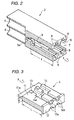
- Fig. 2 is a partially cutaway perspective view of the main portion of the housing in Fig. 1.
- Fig. 3 is a perspective view of the sliding portion in Fig. 1.
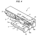
- Fig. 4 is a partially cutaway perspective view of the main portion of the plug type connector including the sliding portion positioned at a first position with respect to the housing in Fig. 1.
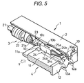
- Fig. 5 is a partially cutaway perspective view of the main portion of the plug type connector including the sliding portion slid toward a second position with respect to the housing in Fig. 4.
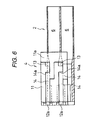
- Fig. 6 is a plan view showing the positional relation of the sliding portion with respect to the housing of Fig. 4.
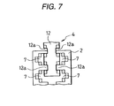
- Fig. 7 is a front view showing the insertion process of the sliding portion with respect to the housing.
- Fig. 8 is a partially cutaway plan view of the main portion of the plug type connector including the sliding portion set to the second position with respect to the housing.
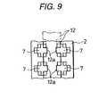
- Fig. 9 is a front view showing a state where the fitting operation of the sliding portion into the housing is completed.
- Fig. 10 is a longitudinal sectional view cut away along a line A-A in Fig. 8.
- Fig. 11 is a perspective view of the sliding portion of a conventional plug type connector.
- Fig. 12 is a partially cutaway side view of the main portion of the conventional plug type connector.
- Fig. 1 is a partially cutaway perspective view of a main portion of the plug type connector according to the invention
- Fig 2 is a partially cutaway perspective view of the main portion of the housing of the plug type connector according to the invention
- Fig. 3 is a perspective view of the sliding portion of the plug type connector according to the invention
- Fig. 4 is a partially cutaway perspective view of the main portion of the plug type connector according to the invention including the sliding portion positioned at a first position with respect to the housing
- Fig. 1 is a partially cutaway perspective view of a main portion of the plug type connector according to the invention
- Fig 2 is a partially cutaway perspective view of the main portion of the housing of the plug type connector according to the invention
- Fig. 3 is a perspective view of the sliding portion of the plug type connector according to the invention
- Fig. 4 is a partially cutaway perspective view of the main portion of the plug type connector according to the invention including the sliding portion positioned at a first position with respect to the housing
- Fig. 1 is
- FIG. 5 is a partially cutaway perspective view of the main portion of the plug type connector according to the invention including the sliding portion slid toward a second position with respect to the housing
- Fig. 6 is a plan view showing the positional relation of the sliding portion with respect to the housing of Fig. 4
- Fig. 7 is a front view showing the insertion process of the sliding portion with respect to the housing
- Fig. 8 is a partially cutaway plan view of the main portion of the plug type connector according to the invention including the sliding portion set to the second position with respect to the housing
- Fig. 9 is a front view showing a state where the fitting operation of the sliding portion into the housing is completed
- Fig. 10 is a longitudinal sectional view cut away along a line A-A in Fig. 8.
- a coupling terminal 3 to be inserted into the plug type connector 1 according to the invention is normally formed in a manner that a metal sheet is subjected to a folding process to form a fastening portion 22 for fastening the coating material 21 of an electric wire, a pressing portion 23 for pressing the core wire 21a of the electric wire, and a contact portion 24 electrically made in contact with the male type terminal of a partner-side connector (not shown) in accordance with the insertion thereof, as shown in Figs. 1, 4 and 5.
- the contact portion 24 has a casing 24a formed in an almost rectangular parallelepiped shape. As shown in Fig. 10, the contact portion is provided at its both side surfaces with tongue-shaped elastic first and second engagement pieces 25a, 25b which are elected therefrom, and further provided with a pair of tongue-shaped elastic contact pieces 24b, 24c which extend toward a terminal insertion inlet 7 from the front end portions of the both side surfaces of the casing 24a, respectively.
- the male type terminal of the partner-side connector (not shown) is passed through the terminal insertion inlet 7 which is opened at the tip end surface 8 of a housing 2 constituting a part of the plug type connector 1 of the embodiment and then inserted with pressure into a space between the pair of opposed contact portions 24b, 24c.
- the partner-side connector is elastically made in contact with the pair of contact portions 24b, 24c and so maintained in an electrically conductive state therewith.
- the housing 2 includes a terminal housing rear portion 6 in which the entirety of the coupling terminal 3 is inserted and a terminal housing front portion 10 which engages with the casing 24a of the contact portion 24 forming a part of the coupling terminal 3.
- the terminal housing front portion 10 includes a stepped end surface at the most inner portion of a fixing contact groove 10a which is provided in a concave shape along the longitudinal direction on the inner surface of the terminal housing front portion.
- the stepped end surface serves as a first engagement portion 10b engaging with the free end portion of the first engagement piece 25a of the casing 24.
- the terminal housing front portion further includes a slanted surface 10c whose thickness is decreased gradually from the first engagement portion 10b toward the inner surface of the terminal housing rear portion 6.
- the terminal housing front portion 10 is provided at the tip end surface 8 and the both side walls thereof with a fitting groove 9 in a notched manner in the longitudinal direction thereof in which a sliding portion 4 for partitioning the terminal housing front portion 10 in the longitudinal direction thereof can be inserted in directions shown by arrows X and Y in Figs. 2, 3 and 5, and further provided at the most inner portion of the fitting groove 9 with a guide groove 9a with a narrow width which guides the sliding portion 4 so that the sliding portion is fitted in the fitting groove.
- the sliding portion 4 includes a base portion 11 of a flat plate shape, a tip end plate 12 provided at the front edge of the base portion 11, and movable bent contact grooves 14 provided in a concave shape on the flat surfaces of the base portion 11.
- the sliding portion further includes second engagement portions 14a which are formed by the bent end surfaces of the movable bent contact grooves 14 and engage with the free end portion of the second engagement pieces 25b of the casings 24a.
- the sliding portion furthermore includes detection projections 13 protrusively provided on the flat surface of the base portion 11 along the movable bent contact grooves 14 at the terminal housing rear portion 6 side from the bent end surface of the movable bent contact grooves 14, and a smooth movement restricting step 11a which is formed by reducing the thickness of the rear edge of the base portion 11 along the entire width thereof.
- the tip end plate 12 is provided with notch portions 12a which are formed by the notching process and form a part of the terminal insertion inlet 7 opened at the tip end surface 8 of the housing 2.
- the notch portions 12a communicate with the movable bent contact grooves 14.
- the effective length L and width W of the sliding portion 4 are set so as to coincide with the effective length 1 and width w of the fitting groove 9, respectively.
- the smooth movement restricting step lla suitably restricts the smooth movement of the sliding portion 4 toward the direction shown by the arrows X and Y when the sliding portion is fitted into the guide groove 9a of the fitting groove 9.
- the detection projection 13 detects whether or not the casing 24a exists in the procedure where the sliding portion 4 slides from the first position relative to the housing 2 shown in Figs. 1, 2, 6 and 7 to the second position relative to the housing 2 shown in Figs. 8 to 10.
- the detection projection further prevents the second engagement piece 25b of the casing 24a engaging with the second engagement portion 14a at the second position from being dropped out.
- the step end surface of the fixing contact groove 10a and the bent end surface of the movable bent contact groove 14 are positioned at the same level in the lateral direction of the terminal housing front portion 10, in order to equally distribute the stress generated at the first and second engagement pieces 25a, 25b by the insertion force of the male type terminal of the partner-side connector.
- the sliding portion 4 may be arranged in a manner that the base portion 11 is provided at both sides thereof with the movable bent contact grooves 14 and the detection projections 13 so that the sliding portion is received within the housing 2 in two stages.
- the sliding portion is continuously pushed thereby to fit the base portion 11 into the fitting groove 9 provided at the terminal housing front portion 10 and also fit the smooth movement restricting step lla into the guide groove 9a, whereby the sliding portion 4 is preset at the first position.
- the detection projection 13 is waiting at the position not interfering the insertion of the coupling terminal 3 between the terminal housing rear portion 6 and the terminal housing front portion 10.
- the coupling terminal 3 is inserted from the terminal housing rear portion 6 side.
- the free end portion of the first engagement piece 25a of the casing 24a moves over the slanted surface 10c while being pressed by the slanted surface 10c.
- the first engagement piece 25a proceeds along the fixing contact groove 10a, and the free end portion of the first engagement piece 25a is released from the pressing force and engages with the first engagement portion 10b.
- the second engagement piece 25b proceeds toward the bottom surface of the movable bent contact groove 14 while being slightly pressed by the flat surface of the smooth movement restricting step lla, the free end portion of the second engagement piece 25b is placed in such a state that the free end can not engage with the second engagement portion 14a of the movable bent contact groove 14.
- the entirety of the sliding portion 4 is not interfered in its sliding movement toward the direction shown by the arrow Y.
- the entirety of the sliding portion 4 is slid to the second position with respect to the housing 2 so that the notch portions 12a move in the direction shown by the arrow Y by 1/2 pitch with respect to the terminal insertion inlet 7.
- the terminal insertion inlet 7 in a fully opened state is defined, and the free end portion of the second engagement piece 25b engages with the second engagement portion 14a due to the movement of the movable bent contact groove 14 toward the direction shown by the arrow Y.
- the detection projection 13 moves to the position abutting against the rear end surface of the casing 24a thereby to close a path along which the casing 24a moves backward.
- the coupling terminal 3 When the coupling terminal 3 is not normally inserted within the housing 2, as shown in Fig. 5, the first engagement piece 25a is kept in a state being pressed by the slanted surface 10c. Thus, the detection projection 13 waits at the position abutting against side wall of the casing 24a, so that the entirety of the sliding portion 4 can not be slid to the second position with respect to the housing 2.
- the double engagement structure of the coupling terminal in the plug type connector according to the invention is arranged in a manner that
- the sliding portion when the sliding portion is preset at the first position with respect to the housing, it becomes possible that the sliding portion allows the casing to be assembled at the terminal housing front portion 10 and also allows the other end portion of the first engagement piece to slide along the fixing contact groove and to engage with the first engagement portion.
- the detection projection can move without being interfered by the abutment against the casing.
- the sliding portion arrives at the second position, it becomes possible that the sliding portion allows the other end portion of the second engagement piece to slide along the movable bent contact groove and engage with the second engagement portion.
- the detection projection serves as a stopper for the casing and prevents the casing from being dropped out, so that it becomes possible that the sliding portion engages the coupling terminal with the first and second engagement portions doubly through the casing by means of the detection projection.
Landscapes
- Details Of Connecting Devices For Male And Female Coupling (AREA)
- Connector Housings Or Holding Contact Members (AREA)
Abstract
Description
Claims (2)
- A double engagement structure of a coupling terminal A plug type connector comprising:wherein said step end surface of said fixing contact groove and said bent end surface of said movable bent contact groove are provided so as to be positioned to a same level in a lateral direction of said terminal housing front portion.a housing;a plurality of terminal housing formed in the housing;a sliding portion fitted into a terminal housing front portion for receiving a contact portion defined by a part of a coupling terminal inserted from a terminal housing rear portion of said housing;a first engagement piece engaged with a first engagement portion defined by a step end surface of a fixing contact groove provided in a concave shape on an inner surface of said housing, an one end of said first engagement piece supported by an one side surface of a casing;a second engagement piece engaged with a second engagement portion defined by a bent end surface of a movable bent contact groove provided in a concave shape on a flat surface of a base portion of said sliding portion, an one end of said second engagement piece supported by the other side surface of said casing; anda detection projection provided protrusively provided on said flat surface of said base portion of said sliding portion along said movable bent contact groove which is close to said terminal housing rear portion side rather than said bent end surface of said movable bent contact groove,
- A double engagement structure of a coupling terminal in a plug type connector according to claim 1, said sliding portion is provided at each of both side surfaces of said base portion with said movable bent contact groove and said detection projection.
Applications Claiming Priority (2)
| Application Number | Priority Date | Filing Date | Title |
|---|---|---|---|
| JP24581299A JP3674830B2 (en) | 1999-08-31 | 1999-08-31 | Double locking structure for connection terminals in plug type connectors |
| JP24581299 | 1999-08-31 |
Publications (2)
| Publication Number | Publication Date |
|---|---|
| EP1081797A2 true EP1081797A2 (en) | 2001-03-07 |
| EP1081797A3 EP1081797A3 (en) | 2002-01-16 |
Family
ID=17139226
Family Applications (1)
| Application Number | Title | Priority Date | Filing Date |
|---|---|---|---|
| EP00307385A Withdrawn EP1081797A3 (en) | 1999-08-31 | 2000-08-29 | Double engagement structure of coupling terminal in plug type connector |
Country Status (3)
| Country | Link |
|---|---|
| US (1) | US6224431B1 (en) |
| EP (1) | EP1081797A3 (en) |
| JP (1) | JP3674830B2 (en) |
Families Citing this family (2)
| Publication number | Priority date | Publication date | Assignee | Title |
|---|---|---|---|---|
| CN109217039B (en) * | 2018-08-23 | 2023-07-25 | 青岛三利智能动力有限公司 | Non-negative pressure water pump plug-in terminal, non-negative pressure water pump, assembling method and control method |
| RS65487B1 (en) * | 2019-02-01 | 2024-05-31 | Komax Holding Ag | Gripper unit for gripping and handling cable ends of two cables, mounting station with the gripper unit and method for the mounting of connector housing |
Family Cites Families (11)
| Publication number | Priority date | Publication date | Assignee | Title |
|---|---|---|---|---|
| US4017141A (en) * | 1973-05-23 | 1977-04-12 | Bury Allen J | Connectors with primary and secondary lock structure |
| US4602836A (en) * | 1984-05-15 | 1986-07-29 | General Motors Corporation | Insulator housing with integrally hinged, snap-in terminal lock |
| JP2700063B2 (en) | 1989-06-27 | 1998-01-19 | 矢崎総業株式会社 | Electrical connector |
| JP2510544Y2 (en) * | 1991-09-04 | 1996-09-11 | 矢崎総業株式会社 | Connector terminal incomplete insertion prevention structure |
| JP2604378Y2 (en) * | 1993-12-06 | 2000-05-08 | 矢崎総業株式会社 | Double locking connector with front holder |
| DE4407950C1 (en) * | 1994-03-09 | 1995-08-17 | Siemens Ag | Electrical connector with a locking device with contact feed |
| DE19536235C1 (en) * | 1995-09-28 | 1997-02-27 | Siemens Ag | Electrical connector with releasable locking device |
| JP3544068B2 (en) * | 1996-07-30 | 2004-07-21 | 住友電装株式会社 | connector |
| JPH1092503A (en) * | 1996-09-17 | 1998-04-10 | Yazaki Corp | Terminal locking structure |
| AU5241698A (en) * | 1996-10-29 | 1998-05-22 | Whitaker Corporation, The | Contact with latch for contact retention and housing therefor |
| JPH1197097A (en) * | 1997-09-24 | 1999-04-09 | Sumitomo Wiring Syst Ltd | Connector with retainer |
-
1999
- 1999-08-31 JP JP24581299A patent/JP3674830B2/en not_active Expired - Fee Related
-
2000
- 2000-08-29 EP EP00307385A patent/EP1081797A3/en not_active Withdrawn
- 2000-08-30 US US09/650,674 patent/US6224431B1/en not_active Expired - Lifetime
Also Published As
| Publication number | Publication date |
|---|---|
| EP1081797A3 (en) | 2002-01-16 |
| JP2001076801A (en) | 2001-03-23 |
| JP3674830B2 (en) | 2005-07-27 |
| US6224431B1 (en) | 2001-05-01 |
Similar Documents
| Publication | Publication Date | Title |
|---|---|---|
| US7938695B2 (en) | Terminal fitting | |
| US5308262A (en) | Electric connector for flexible ribbon cable | |
| EP1094572B1 (en) | A terminal fitting and a connector | |
| US7144281B2 (en) | Female terminal fitting and a blank for a plurality of terminal fittings | |
| US20020182908A1 (en) | Lever-Type Connector | |
| EP1054481A1 (en) | A connector | |
| US6679739B2 (en) | Terminal fitting, a connector provided therewith and use thereof | |
| EP0668639B1 (en) | Bulb socket | |
| EP1635425A1 (en) | Connection terminal | |
| US5980283A (en) | Lever-fitting type connector with lever insertion limitation and withdrawal portion | |
| JP3745634B2 (en) | Terminal fitting | |
| JP3620014B2 (en) | Female terminal and manufacturing method thereof | |
| JP2001167833A (en) | connector | |
| EP1689034B1 (en) | A terminal fitting, connector provided therewith and method of forming a terminal fitting | |
| EP1557908A2 (en) | A connector | |
| US7204728B2 (en) | Terminal fitting and a connector provided therewith | |
| KR20000017090A (en) | A housing for a connector and a connector produced therewith | |
| EP1391970B1 (en) | A connector | |
| US5556304A (en) | Electric connection terminal | |
| US6224431B1 (en) | Double engagement structure of coupling terminal in plug type connector | |
| EP1811608B1 (en) | A terminal fitting and connector provided therewith | |
| US6000972A (en) | Structure for fixing terminal to connector housing | |
| JP3601773B2 (en) | Terminal | |
| EP1199773B1 (en) | Electrical connector and terminal | |
| JPH06150998A (en) | Female terminal fitting |
Legal Events
| Date | Code | Title | Description |
|---|---|---|---|
| PUAI | Public reference made under article 153(3) epc to a published international application that has entered the european phase |
Free format text: ORIGINAL CODE: 0009012 |
|
| AK | Designated contracting states |
Kind code of ref document: A2 Designated state(s): AT BE CH CY DE DK ES FI FR GB GR IE IT LI LU MC NL PT SE Kind code of ref document: A2 Designated state(s): DE ES FR GB IT SE |
|
| AX | Request for extension of the european patent |
Free format text: AL;LT;LV;MK;RO;SI |
|
| PUAL | Search report despatched |
Free format text: ORIGINAL CODE: 0009013 |
|
| AK | Designated contracting states |
Kind code of ref document: A3 Designated state(s): AT BE CH CY DE DK ES FI FR GB GR IE IT LI LU MC NL PT SE |
|
| AX | Request for extension of the european patent |
Free format text: AL;LT;LV;MK;RO;SI |
|
| 17P | Request for examination filed |
Effective date: 20020619 |
|
| AKX | Designation fees paid |
Free format text: DE ES FR GB IT SE |
|
| RAP1 | Party data changed (applicant data changed or rights of an application transferred) |
Owner name: YAZAKI CORPORATION |
|
| GRAP | Despatch of communication of intention to grant a patent |
Free format text: ORIGINAL CODE: EPIDOSNIGR1 |
|
| RTI1 | Title (correction) |
Free format text: PLUG TYPE CONNECTOR WITH DOUBLE ENGAGEMENT STRUCTURE OF COUPLING TERMINAL |
|
| RIN1 | Information on inventor provided before grant (corrected) |
Inventor name: FUKASE, YOSHIHIRO,C/O YAZAKI PARTS CO., LTD. |
|
| STAA | Information on the status of an ep patent application or granted ep patent |
Free format text: STATUS: THE APPLICATION IS DEEMED TO BE WITHDRAWN |
|
| 18D | Application deemed to be withdrawn |
Effective date: 20080715 |