EP1081735A2 - Method and apparatus for manufacturing a framework for shadow mask - Google Patents
Method and apparatus for manufacturing a framework for shadow mask Download PDFInfo
- Publication number
- EP1081735A2 EP1081735A2 EP00118335A EP00118335A EP1081735A2 EP 1081735 A2 EP1081735 A2 EP 1081735A2 EP 00118335 A EP00118335 A EP 00118335A EP 00118335 A EP00118335 A EP 00118335A EP 1081735 A2 EP1081735 A2 EP 1081735A2
- Authority
- EP
- European Patent Office
- Prior art keywords
- framework
- grinding
- shearing
- shadow mask
- basis
- Prior art date
- Legal status (The legal status is an assumption and is not a legal conclusion. Google has not performed a legal analysis and makes no representation as to the accuracy of the status listed.)
- Withdrawn
Links
Images



Classifications
-
- B—PERFORMING OPERATIONS; TRANSPORTING
- B21—MECHANICAL METAL-WORKING WITHOUT ESSENTIALLY REMOVING MATERIAL; PUNCHING METAL
- B21D—WORKING OR PROCESSING OF SHEET METAL OR METAL TUBES, RODS OR PROFILES WITHOUT ESSENTIALLY REMOVING MATERIAL; PUNCHING METAL
- B21D17/00—Forming single grooves in sheet metal or tubular or hollow articles
-
- H—ELECTRICITY
- H01—ELECTRIC ELEMENTS
- H01J—ELECTRIC DISCHARGE TUBES OR DISCHARGE LAMPS
- H01J9/00—Apparatus or processes specially adapted for the manufacture, installation, removal, maintenance of electric discharge tubes, discharge lamps, or parts thereof; Recovery of material from discharge tubes or lamps
- H01J9/02—Manufacture of electrodes or electrode systems
- H01J9/14—Manufacture of electrodes or electrode systems of non-emitting electrodes
- H01J9/142—Manufacture of electrodes or electrode systems of non-emitting electrodes of shadow-masks for colour television tubes
-
- H—ELECTRICITY
- H01—ELECTRIC ELEMENTS
- H01J—ELECTRIC DISCHARGE TUBES OR DISCHARGE LAMPS
- H01J2229/00—Details of cathode ray tubes or electron beam tubes
- H01J2229/07—Shadow masks
- H01J2229/0722—Frame
Definitions
- the present invention relates to methods and apparatuses for manufacturing a framework for a shadow mask used in cathode ray tubes.
- the present invention relates to methods and apparatuses for forming end faces on which a shadow mask is mounted, in which when ends of two opposing side frames positioned in parallel of a rectangular framework are formed into, for example, a curved shape, and a shadow mask is stretched on the end faces, a cylindrical surface formed by the shadow mask can have cylindricity and curvature with high precision.
- a shadow mask is mounted in a cathode ray tube by stretching it on a framework, which is assembled into a rectangular shape by means of welding etc.
- the framework is constructed by fixing a pair of long-side frames arranged horizontally to upper and lower ends of a pair of short-side frames, which are arranged vertically at a distance. Then, a shadow mask is stretched on screen side faces of the long-side frames.
- the end faces of the long-side frames on which a shadow mask is stretched are usually formed into a predetermined curved shape (e.g. a circular arc shape with a radius R) so that their center portions become convex to the screen side.
- a predetermined curved shape e.g. a circular arc shape with a radius R
- the present invention provides methods and apparatuses as follows:
- a first method for manufacturing a framework for a shadow mask according to the present invention includes cutting ends on a screen side of frames constituting two opposing sides of a framework in a predetermined shape by shearing, thereby obtaining end faces on which a shadow mask is stretched, wherein the framework is assembled in an approximately rectangular form.
- a second method for manufacturing a framework for a shadow mask according to the present invention includes: assembling a framework in an approximately rectangular form; grinding a bottom face of the framework, thereby forming a basis plane; and cutting ends on a side opposite to the basis plane of frames constituting two opposing sides of the framework in a predetermined shape by shearing, thereby obtaining end faces on which a shadow mask is stretched.
- the end faces on which a shadow mask is stretched are formed by shearing, and the shearing is carried out in only about several seconds.
- working time can be shortened considerably, and productivity of a framework for a shadow mask is improved significantly.
- the framework when grinding the bottom face of the framework, the framework is placed on a grinding surface that is running, and the bottom face of the framework is ground while restricting movement of the framework in the running direction of the grinding surface. According to such a construction, in the subsequent shearing process, a basis plane for press-fixing the framework to an apparatus can be obtained at the bottom face speedily.
- the bottom face of the framework is ground while substantially no pressurizing force other than the self-weight of the framework is applied in the direction perpendicular to the grinding surface. Accordingly, no external force other than the self-weight acts on the framework when forming the basis plane. Thus, the so-called return distortion is not generated after the grinding, and a basis plane having a very high flatness can be obtained.
- the framework is fixed using the basis plane as an application surface. Accordingly, the so-called return distortion is not generated after the shearing. Furthermore, precision of the distance between the basis plane and the end faces formed by shearing can be increased, and also the generation of a tilt of the end faces with respect to the basis plane can be prevented.
- a basis point for positioning is provided at one point in the framework, and that when ends of the frames constituting two opposing sides are sheared respectively, the positioning of each of the frames in a longitudinal direction is carried out using the basis point. Accordingly, the longitudinal positions of the two end faces formed on the two opposing sides can be allowed to coincide, so that a cylindrical surface formed by a shadow mask stretched on the end faces that are formed into, for example, a curved shape can realize very high cylindricity and accurate curvature.
- a grinding apparatus for a framework for a shadow mask includes: a grinding surface that is running; and a stopper for preventing a framework from moving in a running direction of the grinding surface when the framework is placed on the grinding surface, wherein the framework is assembled in an approximately rectangular form. According to this apparatus, a basis plane for press-fixing the framework to an apparatus in the subsequent shearing process can be obtained speedily.
- substantially no pressurizing force other than the self-weight of the framework is applied in the direction perpendicular to the grinding surface. Accordingly, when forming the basis plane, no external force other than the self-weight acts on the framework. Thus, the so-called return distortion is not generated after the grinding, and a basis plane with a very high flatness can be obtained.
- the grinding surface is a circulating grinding belt, with the grinding belt sliding on a flat-plate shaped bed, and the framework is placed so as to face the bed. Accordingly, a basis plane with a high flatness can be obtained with a simple structure.
- a shearing apparatus for a framework for a shadow mask includes: a die for cutting faces of frames constituting two opposing sides of a framework in a predetermined shape by shearing, wherein the framework is assembled in an approximately rectangular form and has a bottom face as a basis plane, and the faces are on a side opposite to the basis plane; a frame position controlling unit for positioning each of the frames in a longitudinal direction; a base on which the basis plane is applied; and a damper for press-fixing the framework on the base.
- the end faces on which a shadow mask is stretched can be formed by shearing, so that working time can be shortened considerably, and productivity is improved significantly.
- the frame position controlling unit uses a common basis point provided in the framework. Accordingly, longitudinal positions of the two end faces formed on the two opposing sides can coincide, so that a cylindrical surface formed by a shadow mask stretched on the end faces that are formed into, for example, a curved shape can realize very high cylindricity and accurate curvature.
- Fig. 1 is a schematic perspective view showing a configuration of a framework for a shadow mask.
- Fig. 2 also shows a configuration of a framework for a shadow mask: Fig. 2 (A) is a bottom view; Fig. 2 (B) is a left side view; and Fig. 2 (C) is a front view.
- a framework 10 for a shadow mask (a rectangular framework; hereinafter also may simply referred to as "framework") comprises a pair of short-side frames 11a and 11b arranged in parallel, and a pair of long-side frames 12a and 12b arranged in parallel, in which ends of the short-side frames 11a and 11b are bonded to ends of the long-side frames 12a and 12b by welding.
- the short-side frames 11a and 11b are constructed by folding a metal flat plate in an approximately open box shape in cross section.
- the long-side frames 12a and 12b are constructed by folding a metal flat plate in an approximately triangular shape in cross section.
- the metal flat plates of the long-side frames 12a and 12b are extended to the side opposite to the short-side frames 11a and 11b (screen side in a cathode ray tube), and a shadow mask is stretched on end faces 13a and 13b, which are ends of the metal flat plate.
- the end faces 13a and 13b are formed into a shape of a circular arc curve having a predetermined radius R of curvature, so that they are convex to the side opposite to the short-side frames 11a and 11b (screen side in a cathode ray tube).
- the cylindricity of a cylindrical surface 15 (shadow mask surface) formed by the opposing end faces 13a and 13b positioned in parallel is not more than 0.05 mm in the degree of torsion, and cylindricities of end faces 13a and 13b are respectively not more than ⁇ 0.05 mm.
- the cylindricities of the end faces 13a and 13b are different from the cylindricity of the cylindrical surface 15 (shadow mask surface) formed by the end faces 13a and 13b. Even if the end faces 13a and 13b are perfectly cylindrical surfaces, for example, when the center axes of both cylindrical surfaces do not coincide, the surface of the shadow mask stretched on the end faces does not become perfectly cylindrical.
- the end faces 13a and 13b can be formed into a curved shape with high precision within the above range of tolerance.
- short-side frames 11a and 11b and long-side frames 12a and 12b that are obtained by pressing metal flat plates are assembled into a rectangular form and are welded integrally as shown in Figs. 1 and 2. Then, the integrated assembly is annealed to remove intrinsic stresses due to the pressing and welding. At this time, end faces 13a and 13b of the long-side frames 12a and 12b are not formed yet, and as shown by alternate long and two short dashes lines 14a and 14b in Fig. 2 (C), the metal flat plates extend to the side opposite to the short-side frames 11a and 11b.
- bottom faces (faces of the short-side frames on the side not bonded to the long-side frames), which are to be a basis plane, are ground using a grinding apparatus 50 of a belt grinder system shown in Fig. 3.
- the basis plane 17 obtained by the grinding becomes a basis when fixing the framework in a shearing apparatus in the subsequent shearing process.
- numeral 51 denotes a driving motor
- 52 denotes a V-belt for transmitting the power of the driving motor to a driving roller 53
- 54a and 54b denote trailing rollers
- 55a and 55b denote two belt-shaped grinding papers that are run circularly by the driving roller 53 and the trailing rollers 54a and 54b
- 56 denotes a bed having a top surface precisely manufactured with a flatness precision of not more than one hundredth millimeter
- 57a and 57b denote a pair of receiving metallic parts as stoppers.
- a framework 10 is placed so that the basis plane 17 of the short-side frames 11a and 11b respectively corresponds to the grinding papers 55a and 55b that are running at a high speed.
- the two grinding papers 55a and 55b slide closely on the common bed 56, and the framework 10 is placed so as to face the bed 56.
- the surfaces of the grinding papers 55a and 55b do not sink and keep flat surfaces with a precision as high as that of the bed 56. Movement of the framework 10 in the running direction of the grinding papers 55a and 55b is stopped by the receiving metallic parts 57a and 57b.
- the framework 10 in which intrinsic stresses have been removed through annealing after the welding has generated a little distortion in flatness.
- the bottom faces of the framework 10 are placed on the two grinding papers 55a and 55b respectively, and the bottom faces are ground under a load of only the self-weight of the framework 10 in a free condition, without using any fixing measure except for restricting movement in the running direction of the grinding papers 55a and 55b.
- the framework 10 is not distorted during the grinding, and a basis plane 17 with a high flatness precision can be obtained.
- the so-called return distortion is not generated, and a basis plane that is ground precisely with a flatness precision not more than one hundredth millimeter can be formed at the bottom faces of the framework 10.
- linear ends 14a and 14b of the long-side frames before being worked as shown in Fig. 2 (C), which are indicated by an alternate long and two short dashes line, are cut by shearing using a shearing apparatus 100 shown in Figs. 4 to 6, and are formed into a curved shape.
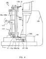
- Fig. 4 is a side view showing a condition in which the framework 10 is set in the shearing apparatus 100.
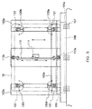
- Fig. 5 is a front view of the shearing apparatus 100, which is viewed from the side of a bottom face (basis plane) of the framework 10.
- the framework 10 is indicated by an alternate long and two short dashes line for simplification.
- a lower die 105a and an upper die 105b function as shearing edges by both dies biting each other.
- the shearing edge has been manufactured to have a shape of a circular arc curve so that the linear upper ends 14a and 14b of the long-side frames can be sheared with a desired radius of curvature R.
- the upper die 105b is fixed to a column 109 of the pressing apparatus 100 so as to be movable up and down.
- the lower die 105a is fixed to a base. When the upper die 105b descends to carry out shearing, it is moved while sliding on a surface of back-up 106 at its back face. Accordingly, escape of the upper the 105b is prevented, and draught clearance between the upper die 105b and the lower die 105a is kept constant.
- a pad 108 supported with a spring 107 is arranged between the lower die 105a and the back-up 106 so that the upper face of the pad 108 is in the same plane as the upper face of the lower die 105a. Accordingly, the shearing can be carried out while sandwiching a cut-side material between the upper die 105b and the pad 108, so that a material on the cut side of the end of the frame can be prevented from escaping in the shearing.
- the framework 10 is set in the shearing apparatus 100 as follows:
- the long-side frame 12a on the lower side is placed on the lower die 105a, and the basis plane 17 as bottom faces of the framework 10 is placed against faces 103a' and 103b' of bases 103a and 103b, which are positioned vertically in the shearing apparatus 100.
- the bases 103a and 103b provided at right and left in a pair have faces 103a' and 103b' respectively against which the framework is applied, which maintain predetermined precisions so as to form an identical plane as well as to cross at right angles the center line of a circular arc of the upper and lower dies 105a and 105b with a radius R of curvature. Accordingly, the framework 10 can be fixed on the bases 103a and 103b with dampers at four corners, which are described below, without having a distortion. Also, when linear ends 14a and 14b of the long-side frames 12a and 12b of the framework 10 before a working are sheared to form a shape of a circular arc, size precision of the distance H (see Fig.
- the frame position controlling unit comprises: a handle 111; a linkage 112 which moves up-and-down linked with the operation of the handle 111; and two position-controlling pins 113a and 113b, which are provided as a pair in the up-and-down direction, and are held for horizontal movement linked with the up-and-down movement of the linkage 112.
- the linkage 112 has a yoke-type structure, in which, by operating the handle 111, two position-controlling pins 113a and 113b are inserted alternatively in the center holes 16a and 16b (see Fig.
- the linkage 112 is arranged so that the two pins 113a and 113b are not inserted in the center holes 16a and 16b simultaneously.
- the lower position-controlling pin 113a is inserted in the center hole 16a of the long-side frame 12a (see Fig. 2 (A)) by operating the handle 111.
- the framework 10 is fixed closely on the bases 103a and 103b with dampers 130a, 130b, 130c and 130d provided at four corners.
- Fig. 6 shows an enlarged side view of the damper 130a at a right lower portion in Fig. 5.
- the clampers provided at four corners have the same basic construction as the clamper 130a in Fig. 6.
- Each clamper comprises: a clamping hook 131 for press-fixing the short-side frame 11a (or 11b) on the base 103a (or 103b), which is mounted at a tip of the clamper; a clamping cam 132 for generating a force for fixing the framework 10; a round-bar shaped connecting pole 133 for connecting the clamping hook 131 and the clamping cam 132 and for moving the clamping hook 131 horizontally as well as rotating it around the axis of the connecting pole 133; a handle 134 that is fixed to the clamping cam 132 for operating the clamping cam 132 and for moving horizontally and rotating the clamping hook 131; and a cam pedestal 135 for keeping the connecting pole 133 to be horizontally movable as well as rotatable and for generating a clamping force by making contact with the clamping cam 132.
- the cam pedestal 135 is fixed on the base 103a (or 130b) with a screw, after adjusting the clamping force of the clamping cam 132, with a long hole parallel to the axial direction of the connecting pole 133.
- the clamping hook 131 is pole-shaped (e.g. a square pole) and is connected to the connecting pole 133 at a position away from the center to one side in the longitudinal direction of the clamping hook 131.
- the procedure for operating the clamper is as follows: Before setting the framework 10, the clamping hook 131 is put in a condition in which it is recessed below the faces 103a' and 103b' of the bases 103a and 103b (a state as indicated by an alternate long and two short dashes line in Fig. 6), and the framework 10 is inserted between the bases 103a and 103b and a column 109 from a lateral side of the shearing apparatus 100. Then, the basis plane 17 of the framework 10 is placed on the faces 103a' and 103b' of the bases 103a and 103b, and the position-controlling pin 113a on the lower side of the frame position controlling unit is inserted in the center hole 16a of the long-side frame 12a.
- the connecting pole 133 is caused to slide forwardly with the handle 134 and then it is rotated, so that the clamping hook 131 is hooked on the short-side frames 11a and 11b of the framework 10.
- the connecting pole 133 is pulled up by moving the handle 134 upward or downward to an approximately perpendicular position and making the clamping cam 132 in contact with a lateral side of the cam pedestal 135, so that the framework 10 is press-fixed on the bases 103a and 103b with the clamping hook 131.
- the procedure for releasing the framework from clamping is as follows:
- the handle 134 is moved rotationally upward or downward in a direction so as to loosen the clamping cam 132, and further is rotated around an axis of the connecting pole 133, so that the clamping hook 131 is released from hooking from the short-side frames 11a and 11b.
- the clamping hook 131 is recessed below the faces 103a' and 103b' by pulling up the handle 134 to the front, and the framework is removed.
- the clamping force of fixing the framework can be kept constant all times, and generation of excessively large or small clamping forces of the framework 10 due to individual differences can be prevented.
- deformation of the framework 10 due to non-uniformity in the clamping force can be prevented, and generation of so-called return-distortion can be prevented.
- a large clamping force can be generated by operating a handle with a small force because of the principle of lever.
- the framework 10 can be fixed as well as can be released from the fixing speedily with a simple structure.
- the center line of the circular arc curve of the upper and lower dies 105a and 105b can coincide with the center lines of the framework 10, that is, the center lines C of the circular arc curves of the end faces 13a and 13b shown in Fig. 2.
- the frame 1 is turned upside down, and a curved shape of an end face 13b of the long-side frame 12b on the other side is formed.
- the method of setting the framework 10 as well as the order and method of forming a curved shape are basically the same as the above.
- the position-controlling pin 113b on the upper side of the frame position controlling unit is inserted in the center hole 16a of the long-side frame 12a, in which a curved end face 13a has been already formed. That is, at both two times of shearing operations, position of the framework is controlled using a common basis point, namely, a center hole formed in the long-side frame on the same side (in the above example, the center hole 16a).
- center hole 16b provided in the long-side frame 13b is used as needed when assembling the framework, but is not used for positioning in the shearing.
- end faces on the screen side of long-side frames are sheared into a curved shape
- the present invention is not limited to this example.
- the present invention also can be applied to the case in which end faces of long-side frames are sheared in a straight shape and a planar shadow mask is manufactured.
- a basis plane for forming end faces of frames is produced by grinding bottom faces of a rectangular framework in free condition without applying any pressure to the framework, so that no return distortion is generated after the grinding, and a basis plane having a flatness with high precision of not more than one hundredth milimeter can be formed.
- end faces with high precision can be formed by shearing using a conventional pressing machine with dies. Moreover, because shearing is employed, the working can be carried out rapidly in only several seconds.
- the grinding apparatus of a belt grinder system for a basis plane by running two belt-like grinding papers closely on a bed, flat surfaces that are ground with a high flatness precision as mentioned above can be obtained, and a basis plane of a rectangular framework can be formed rapidly with high precision. Furthermore, the apparatus does not require any jig for fixing the rectangular framework other than a jig for preventing the rectangular framework from moving in the running direction of the grinding belt, so that cost of equipment can be reduced.
- the shearing apparatus for forming for example, a curved shape for the end faces of the frames on which a shadow mask is mounted
- positioning is carried out by inserting a position-controlling pin in one center hole provided in a rectangular framework at two times in the shearing operations, the center lines of the circular arc curves formed on two sides of the framework can coincide.
- the clamper for fixing the framework uses a cam for clamping, the framework can be fixed by clamping with a predetermined clamping force, generation of return distortion due to non-uniformity of the clamping force can be prevented, and operations of setting and removing the framework can be simplified.
- the center line of the circular arc curve of the dies and the center lines of the circular arc curves on two sides of the framework can coincide with high precision, and the cylindricity of a cylindrical surface formed by end faces on two sides, on which a shadow mask is mounted, can be improved.
- the shearing apparatus of the present invention can be configured by setting necessary equipment in a conventional pressing machine. Moreover, shearing into a predetermined shape can be carried out instantly with the dies set in the apparatus.
Landscapes
- Engineering & Computer Science (AREA)
- Manufacturing & Machinery (AREA)
- Mechanical Engineering (AREA)
- Grinding And Polishing Of Tertiary Curved Surfaces And Surfaces With Complex Shapes (AREA)
- Punching Or Piercing (AREA)
- Finish Polishing, Edge Sharpening, And Grinding By Specific Grinding Devices (AREA)
- Electrodes For Cathode-Ray Tubes (AREA)
Abstract
Description
Claims (11)
- A method for manufacturing a framework for a shadow mask, which comprises cutting ends on a screen side of frames constituting two opposing sides of a framework in a predetermined shape by shearing, thereby obtaining end faces on which a shadow mask is stretched, wherein the framework is assembled in an approximately rectangular form.
- A method for manufacturing a framework for a shadow mask, which comprises:assembling a framework in an approximately rectangular form;grinding a bottom face of the framework, thereby forming a basis plane;cutting ends on a side opposite to the basis plane of frames constituting two opposing sides of the framework in a predetermined shape by shearing, thereby obtaining end faces on which a shadow mask is stretched.
- The method according to claim 2, wherein when grinding the bottom face of the framework, the framework is placed on a grinding surface that is running, and the bottom face of the framework is ground while restricting movement of the framework in a running direction of the grinding surface.
- The method according to claim 3, wherein the bottom face of the framework is ground while substantially no pressurizing force other than a self-weight of the framework is applied in a direction perpendicular to the grinding surface.
- The method according to claim 2, wherein when the shearing is carried out, the framework is fixed using the basis plane as an application surface.
- The method according to claim 1 or 2, wherein a basis point for positioning is provided at one point in the framework, and wherein when ends of the frames constituting two opposing sides are sheared respectively, positioning of each of the frames in a longitudinal direction is carried out using the basis point.
- A grinding apparatus for a framework for a shadow mask, comprising: a grinding surface that is running; and a stopper for preventing a framework, which is assembled in an approximately rectangular form, from moving in a running direction of the grinding surface when the framework is placed on the grinding surface.
- The grinding apparatus according to claim 7, which applies substantially no pressurizing force other than a self-weight of the framework in a direction perpendicular to the grinding surface.
- The grinding apparatus according to claim 7, wherein the grinding surface is a circulating grinding belt, the grinding belt sliding on a flat-plate shaped bed, and the framework is placed so as to face the bed.
- A shearing apparatus for a framework for a shadow mask, comprising:a die for cutting ends of frames constituting two opposing sides of a framework in a predetermined shape by shearing, wherein the framework is assembled in an approximately rectangular form and has a bottom face as a basis plane, and the ends are on a side opposite to the basis plane;a frame position controlling unit for positioning each of the frames in a longitudinal direction;a base against which the basis plane is placed; anda clamper for press-fixing the framework on the base.
- The shearing apparatus according to claim 10, wherein when the frames constituting two opposing sides are sheared respectively, positioning of each of the frames is carried out by the frame position controlling unit using a common basis point provided in the framework.
Applications Claiming Priority (2)
| Application Number | Priority Date | Filing Date | Title |
|---|---|---|---|
| JP25010699 | 1999-09-03 | ||
| JP25010699 | 1999-09-03 |
Publications (2)
| Publication Number | Publication Date |
|---|---|
| EP1081735A2 true EP1081735A2 (en) | 2001-03-07 |
| EP1081735A3 EP1081735A3 (en) | 2004-01-28 |
Family
ID=17202919
Family Applications (1)
| Application Number | Title | Priority Date | Filing Date |
|---|---|---|---|
| EP00118335A Withdrawn EP1081735A3 (en) | 1999-09-03 | 2000-08-24 | Method and apparatus for manufacturing a framework for shadow mask |
Country Status (4)
| Country | Link |
|---|---|
| US (1) | US6817919B1 (en) |
| EP (1) | EP1081735A3 (en) |
| KR (1) | KR100434652B1 (en) |
| CN (3) | CN1516217A (en) |
Families Citing this family (3)
| Publication number | Priority date | Publication date | Assignee | Title |
|---|---|---|---|---|
| US20040245908A1 (en) * | 2003-06-03 | 2004-12-09 | Keizou Makino | Support frame structure, cathode ray tube, and manufacturing method of color selection structure |
| CN105304432B (en) * | 2015-11-16 | 2017-04-26 | 西北核技术研究所 | Device for grinding graphite cathode surface of electron beam diode |
| JP7122651B2 (en) * | 2017-02-09 | 2022-08-22 | パナソニックIpマネジメント株式会社 | image display device |
Family Cites Families (9)
| Publication number | Priority date | Publication date | Assignee | Title |
|---|---|---|---|---|
| JPS5451775A (en) * | 1977-09-30 | 1979-04-23 | Sony Corp | Grid device for color cathode-ray tube |
| JPS5835842A (en) * | 1981-08-26 | 1983-03-02 | Sony Corp | Grid device for color cathode-ray tube |
| JPH04144027A (en) | 1990-10-03 | 1992-05-18 | Nec Corp | Manufacture of color picture tube |
| JPH06187918A (en) * | 1992-12-16 | 1994-07-08 | Sony Corp | Color selection mechanism for cathode-ray tube |
| US5644192A (en) * | 1995-11-15 | 1997-07-01 | Thomson Consumer Electronics, Inc. | Color picture having a tensioned mask and compliant support frame assembly |
| FR2749104B1 (en) | 1996-05-22 | 1998-08-28 | Imphy Sa | PERFORATED MASK FRAME OF A CATHODE RAY TUBE AND MANUFACTURING METHOD |
| DE19723306C2 (en) | 1997-06-04 | 2002-05-29 | Zech Hans Jochen | Method and device for grinding or polishing end faces of plate-shaped bodies |
| JPH11204027A (en) | 1998-01-09 | 1999-07-30 | Sony Corp | Method of manufacturing color selection electrode and frame of color selection electrode |
| KR100339376B1 (en) * | 1999-08-13 | 2002-06-03 | 구자홍 | support frame for color cathode ray tube |
-
2000
- 2000-08-17 US US09/640,424 patent/US6817919B1/en not_active Expired - Fee Related
- 2000-08-24 EP EP00118335A patent/EP1081735A3/en not_active Withdrawn
- 2000-09-01 CN CNA031285163A patent/CN1516217A/en active Pending
- 2000-09-01 CN CNA031285155A patent/CN1516216A/en active Pending
- 2000-09-01 CN CNB001268791A patent/CN1146938C/en not_active Expired - Fee Related
- 2000-09-02 KR KR10-2000-0051852A patent/KR100434652B1/en not_active Expired - Fee Related
Also Published As
| Publication number | Publication date |
|---|---|
| US6817919B1 (en) | 2004-11-16 |
| CN1287375A (en) | 2001-03-14 |
| CN1516217A (en) | 2004-07-28 |
| EP1081735A3 (en) | 2004-01-28 |
| CN1146938C (en) | 2004-04-21 |
| CN1516216A (en) | 2004-07-28 |
| KR20010030247A (en) | 2001-04-16 |
| KR100434652B1 (en) | 2004-06-04 |
Similar Documents
| Publication | Publication Date | Title |
|---|---|---|
| JP3485041B2 (en) | Press machine | |
| US6817919B1 (en) | Method and apparatus for manufacturing a frame work for shadow mask | |
| JPH08224619A (en) | Work bending method and device therefor | |
| JPH07178476A (en) | Press die changer | |
| JP2558928Y2 (en) | Press brake | |
| CN219562772U (en) | Frame positioning structure | |
| KR101986529B1 (en) | Clamper and clamping system | |
| US5348506A (en) | Method of assembling a shadow mask and an apparatus for carrying out the same | |
| JP2001143615A (en) | Method and apparatus for manufacturing shadow mask frame | |
| JPH08537U (en) | Bending device | |
| JPH09207091A (en) | Cutting device | |
| KR102011722B1 (en) | Producing system of mask integrated frame | |
| JPH0531537A (en) | How to process difficult-to-process thin metal sheets | |
| JP2924701B2 (en) | Wrinkle holding method and wrinkle holding device for press machine | |
| CN119035339B (en) | End cover flanging integrated forming machine | |
| JP2995498B2 (en) | Clamp fixing device for leaf spring | |
| KR100220808B1 (en) | Manufacture of frame for shadowmask | |
| JP3552120B2 (en) | Oblique end-close processing method and processing press device for deck plate | |
| JPH0531539A (en) | Working method for hard-to-work thin metallic plate | |
| CN223043928U (en) | A rapid positioning device for sheet metal welding | |
| US5169351A (en) | Shadow mask heating apparatus for color CRT of the flat faceplate type | |
| KR20190096896A (en) | Producing method of mask integrated frame | |
| JPH08167376A (en) | Aperture grill assembly method and assembly apparatus | |
| CN121820973A (en) | Arc triangle gate welding frock | |
| JPH08106858A (en) | Shadow mask for color cathode ray tube and manufacturing method thereof |
Legal Events
| Date | Code | Title | Description |
|---|---|---|---|
| PUAI | Public reference made under article 153(3) epc to a published international application that has entered the european phase |
Free format text: ORIGINAL CODE: 0009012 |
|
| AK | Designated contracting states |
Kind code of ref document: A2 Designated state(s): AT BE CH CY DE DK ES FI FR GB GR IE IT LI LU MC NL PT SE |
|
| AX | Request for extension of the european patent |
Free format text: AL;LT;LV;MK;RO;SI |
|
| RAP1 | Party data changed (applicant data changed or rights of an application transferred) |
Owner name: MATSUSHITA ELECTRIC INDUSTRIAL CO., LTD. |
|
| PUAL | Search report despatched |
Free format text: ORIGINAL CODE: 0009013 |
|
| AK | Designated contracting states |
Kind code of ref document: A3 Designated state(s): AT BE CH CY DE DK ES FI FR GB GR IE IT LI LU MC NL PT SE |
|
| AX | Request for extension of the european patent |
Extension state: AL LT LV MK RO SI |
|
| RIC1 | Information provided on ipc code assigned before grant |
Ipc: 7B 24B 21/04 B Ipc: 7B 23D 23/00 B Ipc: 7H 01J 9/14 A |
|
| 17P | Request for examination filed |
Effective date: 20040515 |
|
| 17Q | First examination report despatched |
Effective date: 20040706 |
|
| AKX | Designation fees paid |
Designated state(s): DE FR GB IT NL |
|
| GRAP | Despatch of communication of intention to grant a patent |
Free format text: ORIGINAL CODE: EPIDOSNIGR1 |
|
| STAA | Information on the status of an ep patent application or granted ep patent |
Free format text: STATUS: THE APPLICATION IS DEEMED TO BE WITHDRAWN |
|
| 18D | Application deemed to be withdrawn |
Effective date: 20060216 |